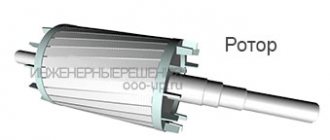
A significant number of drive systems are used to naturally slow down engines when stopped. The time it takes to stop the rotor is measured solely by the inertial moment and the moment of resistance to rotation. Meanwhile, the operation of systems often requires reducing the stopping time of the motor shaft, and in this case, electrical braking of the electric motor seems to be a simple and effective solution. Compared to devices that use mechanical or hydraulic methods, electrical braking of motors has clear advantages in terms of stability of operation and cost-effectiveness of use.
Options for constructing electric brakes
Let's consider several options for braking motors electrically, which can be applied in practice. At the same time, we note the possibility of using braking mechanisms in relation to electric motors of different types. The list of braking techniques considered includes the following:
- countercurrent,
- DC input,
- electronically,
- supersynchronous speed,
- in other ways.
Schemes of capacitor braking of electric motors
Capacitor braking of asynchronous motors
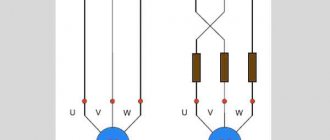
The figure shows a diagram of turning on the motor with capacitor braking. Capacitors are connected in parallel to the stator winding, usually connected in a delta circuit.
When the motor is disconnected from the network, the discharge currents of the capacitors create a magnetic field rotating at a low angular velocity. The machine goes into regenerative braking mode, the rotation speed is reduced to a value corresponding to the rotation frequency of the excited field. During the discharge of capacitors, a large braking torque appears, which decreases with decreasing rotation speed.
At the beginning of braking, the kinetic energy stored by the rotor is quickly absorbed with a short braking distance. Braking is sharp, impact torques reach 7 Mn. The peak value of the braking current at the highest capacitance values does not exceed the starting current.
As the capacitor capacity increases, the braking torque increases and braking lasts to a lower speed. Studies have shown that the optimal capacity value lies in the range of 4 - 6 sleeps. Capacitor braking stops at a rotation speed of 30 - 40% of the rated speed, when the rotor speed becomes equal to the stator field speed due to free currents arising in the stator. In this case, during the braking process, more than 3/4 of the kinetic energy stored by the drive is absorbed.
To completely stop the engine according to the diagram in Figure 1, a, there must be a moment of resistance on the shaft. The described scheme is distinguished by the absence of switching devices, ease of maintenance, reliability and efficiency.
When connecting capacitors directly in parallel with the motor, you can use only types of capacitors that are designed for long-term operation in an alternating current circuit.
If braking is carried out according to the scheme in Figure 1 with the connection of capacitors after disconnecting the engine from the network, it is possible to use cheaper and small-sized metal-paper capacitors of the MBGP and MBGO types, designed for operation in direct and pulsating current circuits, as well as dry polar electrolytic capacitors (CE, KEG and etc.).
It is advisable to use capacitor braking with capacitors tightly connected in a triangle configuration for quick and accurate stopping of electric drives on the shaft of which a load torque of at least 25% of the rated motor torque is applied.
For capacitor braking, a simplified scheme can be used: single-phase connection of capacitors (Fig. 1.6). To obtain the same braking effect as with a three-phase connection of a capacitor, it is necessary that the capacitance of the capacitor in a single-phase circuit be 2.1 times greater than the capacitance in each phase in the circuit in Fig. 1, a. However, the capacitance in a single-phase circuit is only 70% of the total capacitance of the capacitors when they are connected three-phase.
Energy losses in the motor during capacitor braking are the smallest compared to other types of braking, so it is recommended for electric drives with a large number of starts.
When choosing equipment, it should be taken into account that the contactors in the stator circuit must be designed for the current flowing through the capacitors. To eliminate the disadvantage of capacitor braking - stopping the action until the electric motor stops completely - it is used in combination with dynamic magnetic braking.
Countercurrent braking principle
The motor is disconnected from the power supply, and while the rotor continues to rotate, it is reconnected in antiphase. Such a system creates an effective locking torque, usually higher than the starting torque.
Meanwhile, this effective braking torque must be quickly neutralized so that the engine does not rotate in the opposite direction after stopping. Several control and automation devices are used to ensure that the rotation of the electric motor shaft is slowed down until it stops completely:
- clutch stop sensors,
- centrifugal stop sensors,
- chronometric instruments,
- frequency relay,
- rotor voltage relay (for wound-rotor motors), etc.
Braking a squirrel-cage motor
Before choosing a countercurrent system for an asynchronous motor with a short-circuit rotor, it is important to ensure the resistance of the motor to the countercurrent method, taking into account the required load.
In addition to mechanical stress, this process exposes the rotor to high thermal loads as the energy generated by each operation is dissipated in the rotor body.
The thermal stress in the counterflow is three times greater than when the rotation speed increases. Here the peaks of current and torque are noticeably higher when compared with the starting moment.
The principle of the countercurrent technique on the electric motor circuit in order to quickly slow down and then stop. On the left is the normal operating cycle. On the right is the deceleration and stopping cycle
Therefore, to ensure a smooth stop of the engine by the countercurrent system, as a rule, a resistor is installed in series with each stator phase. Thanks to this addition, when switching, the torque and current are reduced to values equal to those noted on the stator in starting mode.
However, the countercurrent braking system has a number of serious disadvantages. Therefore, this method for asynchronous motors with a squirrel-cage rotor is used in rare cases and mainly on low-power motors.
Countercurrent braking on wound-rotor motors
To limit the current and torque before the stator is switched to countercurrent running, the rotor resistors used for starting are essential.
In this case, an additional resistive braking section should be periodically added. With the correct value of the rotor resistor, adjusting the braking torque to the required value is easy.
The moment of current switching gives the rotor voltage almost twice as much as when the rotor is at rest, which sometimes requires special measures for insulation.
The principle of countercurrent electrical blocking on motors with wound rotor. On the left is normal operation. Right - deceleration and stop
As with power motors, the rotor circuit produces a significant amount of energy. All released energy is completely dissipated in resistors (except for small losses).
The engine can be stopped automatically by one of the above mentioned control devices. For example, using a voltage or frequency relay in the rotor circuit. Using a counterflow circuit, it is possible to maintain the driving load at a moderate speed.
However, the characteristic is extremely unstable (significant fluctuations in speed relative to small changes in torque).
Regeneration mode in asynchronous electric machines
The recuperation mode is used not only in DC motors. It can also be used in asynchronous motors.
However, this mode is possible in the following cases:
- If you change the frequency of the supply voltage using a frequency converter. This is possible provided that the asynchronous electric motor is powered from a device with the ability to regulate the frequency of the supply network. The braking effect occurs when the frequency of the supply voltage decreases. In this case, the transition to generator mode occurs when the rotor rotation speed becomes higher than the nominal (synchronous) one.
- Asynchronous machines, which are structurally capable of switching windings to change speed.
- In lifting mechanisms where power descent is used. An electric motor with a wound rotor is mounted in them. In this case, the speed is adjusted by changing the value of the resistor connected to the rotor windings. The magnetic flux begins to overtake the stator field, and the slip becomes greater than 1. The electric motor switches to generator mode, the generated electricity returns to the network, and a braking effect occurs.
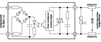
DC injection braking
This option is used on motors with wound and squirrel-cage rotors. Compared to a countercurrent system, the cost of using a rectified current source is offset by fewer resistors.
Thanks to electronic speed controllers and starters, this method of braking asynchronous electric motors seems to be quite economical.
Stopping principle by DC injection. This system requires a constant voltage source to operate. Voltage requirements are not critical
The technique involves disconnecting the stator windings from the network and supplying rectified current to the windings. The passage of rectified current through the stator windings is accompanied by the formation of a fixed flux in the air gap between the rotor and the stator ring of the motor.
To achieve a value of this flux that can provide proper braking, the current must be approximately 1.3 times the rated current. The excess heat loss inevitably caused by this slight excess is usually compensated by a temporary pause after stopping the motor.
Criteria for applying the DC injection method
Since the current value depends on the resistance of the stator winding, the voltage at the rectified current source is low. Typically the source is a rectifier or speed controller circuit.
These rectified current sources must be adapted to the transient voltage surges that occur on the windings when disconnected from the AC power source.
The rotor movement here should be considered as sliding relative to a field fixed in space. The behavior of the motor is similar to that of a synchronous generator with unloading on the rotor. Therefore, the differences in the characteristics obtained during braking by introducing a rectified current are important, compared to a countercurrent circuit:
- Less energy is dissipated in the rotor resistors or in the rotor body. The process is equivalent to the mechanical energy released en masse during movement. The only power consumed from the network is the stator excitation.
- When the load is not controllable, the motor will not start in the opposite direction.
- If the load is controllable, the system operates continuously and keeps the load at low speed. That is, a deceleration factor is achieved, rather than complete braking. The performance is much more stable than that of a counterflow system.
On wound-rotor motors, the torque characteristics depend on the choice of resistors.
Option of braking resistors: 1 - heating sensor; 2 - metal shunt; 3 - high-temperature conductor; 4 - wire resistive element; 5 - temperature block; 6 - body
On squirrel-cage motors, the system allows you to easily adjust the braking torque of the electric motor, influencing the DC energy. However, the braking torque remains low if the engine is running at high speeds.
Asynchronous motors with wound rotor: pros and cons
As mentioned above, when compared with a squirrel-cage motor, it has two main advantages:
- possibility of starting the motor with a significant load already connected to the shaft – the motor generates high torque from the very beginning
- switching current limitation allows the installation of asynchronous motors with a phase rotor in low-power networks.
In addition, other advantages should be noted:
- ability to work with heavy overload
- small fluctuations in rotation speed - under different loads the rotation speed remains approximately the same
- possibility of installing automation – starting devices
Let's note the disadvantages:
- the introduction of resistors into the rotor circuit complicates and increases the cost of the engine
- large dimensions
- lower efficiency and cos φ than squirrel-cage motors
- at underload the cos φ value has minimal values
In practice, asynchronous motors with a wound rotor are optimally suited for cases where there is no need for wide and smooth speed control and very high (especially at the initial stage) engine power is required.
To correctly connect an asynchronous motor, it is important to correctly determine the beginnings and ends of the phase windings. How to do this - discussed in detail in the video
Electronic and super-synchronous engine braking
The effect of electronic braking is achieved relatively simply by using a speed controller equipped with a braking resistor. An asynchronous motor acts as a generator. Mechanical energy is dissipated in the limiting resistor without increasing losses in the motor itself.
The braking effect occurs when the motor reaches the top of the synchronous speed and moves to higher values. Here the asynchronous generator mode is actually initiated and the braking torque develops. The resulting energy losses are restored by the power grid.
A similar operating mode occurs on lift motors when lowering loads at rated speed. The braking torque is completely balanced by the torque from the load.
Due to this balance, it is possible to brake not by reducing the speed, but by bringing the engine into operation at a constant speed.
For the operation of wound-rotor motors, all or part of the rotor resistors must be short-circuited so that the motor does not develop movement significantly above the rated speed.
The supersynchronous system appears to be functionally ideal for limiting movement under load because:
- The speed remains stable and is practically independent of torque,
- Energy is recovered and renewed on the grid.
However, supersynchronous braking of electric motors only maintains one rotation speed, typically the rated rotation. Frequency-controlled motors use supersynchronous circuits, due to which the shaft rotation speed changes from a high value to a low value.
Supersynchronous braking is easily achieved by using an electronic speed controller, which automatically activates this system when the frequency is reduced.
Other braking systems
Rarely, but still there are single-phase braking systems. This technique powers the motor between two mains phases and connects the unoccupied terminal to one of the other two mains connections.
Stopping option by simple reverse switching - reversing the rotation field formed by the stator windings
The braking torque is limited to 1/3 of the maximum motor torque. This system cannot stop the engine at full load.
Therefore, this scheme is traditionally complemented by a countercurrent method. The single-phase blocking option is characterized by significant imbalance and high losses.
Electric motor braking is also used by weakening eddy currents. The principle at work here is similar to that used on industrial vehicles in addition to mechanical braking (electrical gearboxes).
Mechanical energy is dissipated in the speed reducer. Slowing down and stopping the electric motor is controlled by simply energizing the winding. A significant disadvantage of this method is a significant increase in inertia.
Regenerative braking of electric cars
Regenerative braking of an electric motor is characterized by switching the engine to generator mode. In this case, the generated electricity is returned to the network or used to recharge the battery.
This mode is widely used in electric locomotives, electric trains, trams and trolleybuses. At the moment of braking, the generated electricity is returned to the electrical network.
The regenerative braking mode is used to recharge batteries in hybrid cars, electric vehicles, electric scooters, and electric bicycles.
This mode is the most economical and is possible under the following conditions: if the rotor speed exceeds the idle speed. This condition is met when the EMF of the electric motor exceeds the supply voltage. And the armature current and magnetic flux change their direction. The electric machine switches to generator mode, and a braking moment occurs.
The figure shows a diagram of the braking of a traction motor: a) with independent excitation and stabilizing resistance, b) with counter-excitation of the exciter.