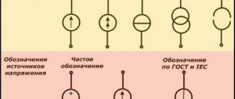
A synchronous compensator is a lightweight synchronous motor designed to operate at idle speed. The main consumers of electrical energy, in addition to active power, consume reactive power from the system generators. Consumers that require large magnetizing reactive currents to create and maintain magnetic flux include asynchronous motors, transformers, induction furnaces and others. Therefore, distribution networks usually operate with lagging current.
The reactive power generated by the generator is obtained at the lowest cost. However, the transfer of reactive power from generators is associated with additional losses in transformers and transmission lines. Therefore, to obtain reactive power, it becomes economically profitable to use synchronous compensators located at the system's node substations or directly at consumers.
Synchronous motors, thanks to direct current excitation, can operate with cos = 1 and do not consume reactive power from the network, and when operating with overexcitation they supply reactive power to the network. As a result, the power factor of the network is improved and the voltage drop and losses in it are reduced, and the power factor of generators operating in power plants is increased.
Synchronous compensators are designed to compensate the network power factor and maintain a normal network voltage level in areas where consumer loads are concentrated.
In an overexcited mode, the current leads the network voltage, i.e., it is capacitive in relation to this voltage, and in underexcited modes it is lagging, inductive. In this mode, the synchronous machine turns into a compensator - into a reactive current generator.
The normal mode is the overexcited mode of operation of the synchronous compensator, when it supplies reactive power to the network.
Synchronous compensators do not have drive motors and, from the point of view of their operating mode, are essentially synchronous motors operating at no load.
To do this, each synchronous compensator is equipped with an automatic excitation or voltage regulator, which regulates the magnitude of its excitation current so that the voltage at the compensator terminals remains constant.
In order to improve the power factor and accordingly reduce the shift angle between current and voltage from the value φst to φk, reactive power is needed:
where P is the average active power, kvar; φsv - phase shift corresponding to the weighted average power factor; φк is the phase shift that should be obtained after compensation; a is a coefficient equal to about 0.9, introduced into the calculations in order to take into account a possible increase in the power factor, without installing compensating devices.
In addition to compensating reactive currents of inductive industrial loads, synchronous compensators are needed on power lines. In long power lines at low loads, line capacitance predominates, and they operate with leading current. In order to compensate for this current, the synchronous compensator must operate with a lagging current, i.e., underexcited.
With a significant load on the power line, when the inductance of electricity consumers predominates, the power line operates with a lagging current. In this case, the synchronous compensator must operate with a leading current, i.e., overexcited.
A change in the load on a power line causes a change in reactive power flows in magnitude and phase, leading to significant voltage fluctuations in the line. In this regard, there is a need for its regulation.
Synchronous compensators are usually installed at regional substations.
To regulate the voltage at the end or middle of transit power lines, intermediate substations with synchronous compensators can be created, which must regulate or maintain the voltage constant.
The operation of such synchronous compensators is automated, which creates the possibility of smooth automatic regulation of the amount of generated reactive power and voltage.
To implement asynchronous starting, all synchronous compensators are equipped with starting windings in pole pieces or their poles are made massive. In this case, the direct method is used, and, in necessary cases, the reactor start-up method.
In some cases, powerful compensators are also put into operation using starting phase asynchronous motors mounted on the same shaft with them. To synchronize with the network, the self-synchronization method is usually used.
Since synchronous compensators do not develop active power, the question of static stability of operation for them becomes less pressing. Therefore, they are manufactured with a smaller air gap than generators and engines. Reducing the gap makes it easier to field winding and reduces the cost of the machine.
The rated total power of a synchronous compensator corresponds to its operation with overexcitation, i.e. The rated power of a synchronous compensator is its reactive power at leading current, which it can carry for a long time in operating mode.
The highest current and power values in the underexcited mode are obtained when operating in the reactive mode.
In most cases, the underexcited mode requires less power than the overexcited mode, but in some cases more power is needed. This can be achieved by increasing the gap, but this leads to an increase in the cost of the machine, and therefore, recently the question of using a mode with a negative excitation current has been raised. Since the synchronous active power compensator is loaded only with losses, then, according to it, it can also operate stably with a slight negative excitation.
In some cases, during low-water periods, hydroelectric generators are also used to operate in compensator mode.
In terms of design, compensators are not fundamentally different from synchronous generators. They have the same magnetic system, excitation system, cooling, etc. All medium-power synchronous compensators are air-cooled and are made with an exciter and subexciter.
Due to the fact that synchronous compensators are not designed to perform mechanical work and do not carry an active load on the shaft, they have a mechanically lightweight design. Compensators are designed as relatively low-speed machines (1000 - 600 rpm) with a horizontal shaft and a salient pole rotor.
A generator running idle with appropriate excitation can be used as a synchronous compensator. In an overexcited generator, a balancing current appears, which is purely inductive relative to the generator voltage and purely capacitive relative to the network.
It should be borne in mind that an overexcited synchronous machine, regardless of whether it operates as a generator or a motor, can be considered relative to the network as capacitance, and an underexcited one as inductance.
In order to switch a generator connected to the network into synchronous compensator mode, it is enough to close the access of steam (or water) to the turbine. In this mode, an overexcited turbogenerator begins to consume a small active power from the network only to cover rotation losses (mechanical and electrical) and supplies reactive power to the network.
In synchronous compensator mode, the generator can operate for a long time and depends only on the operating conditions of the turbine.
If necessary, the turbogenerator can be used as a synchronous compensator both with the turbine rotating (together with the turbine) and with the articulation coupling disconnected, i.e., disassembled.
Rotation of the steam turbine from the generator side, which has switched to propulsion mode, can cause overheating of the tail section of the turbine.
If you liked this article, share a link to it on social networks. This will greatly help the development of our site!
Subscribe to our channel on Telegram!
Just follow the link and connect to the channel.
Don't miss updates, subscribe to our social networks:
Source
Synchronous compensators
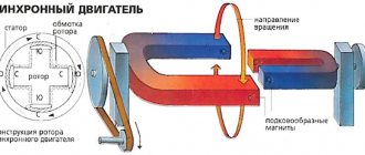
A synchronous compensator is a synchronous machine operating in motor mode without load on the shaft with a changing field current. Depending on the excitation current, a synchronous compensator can supply reactive power to the network or consume it from the network. A general view of the synchronous compensator is shown in Fig. 1.
Fig.1. General view of a synchronous compensator with hydrogen cooling when installed openly at a power system substation
Structurally, it is similar to a turbogenerator, however, it operates at an average rotation speed (750-1000 rpm). The rotor of the synchronous compensator is made salient-pole. The stator is structurally similar to the stator of a turbogenerator.
A synchronous compensator is characterized by rated power, stator voltage and current, frequency, rated rotor current and losses in rated mode.
Rated voltage
The rated voltage of the synchronous compensator in accordance with GOST is set to 5 or 10% higher than the corresponding rated voltage of the electrical network.
Rated power
The rated power of a synchronous compensator is determined as the long-term permissible load at rated voltage and rated parameters of the cooling medium.
The rated powers of synchronous compensators are determined in kilovolt-amperes and must correspond to a number of powers in accordance with GOST 609-84. According to this GOST, the minimum power of a synchronous compensator is determined to be 2800 kVA. The maximum power of compensators produced in the past in the USSR was 160 MBA.
Rated stator current
The rated stator current is determined based on the rated power and rated voltage.
Rated rotor current
Active power losses under nominal cooling conditions for synchronous compensators are in the range of 1.5-2.5%.
Modern electrical loads are characterized by significant consumption of reactive power. The growth in reactive power consumption is associated primarily with the widespread use of electrical installations in which magnetic fields are used to convert energy (electric motors, transformers, etc.). The currents of converting devices with mercury valves and thyristors, fluorescent lighting, etc. have a significant reactive component. In this regard, electrical networks are loaded with a reactive component of the current, which is accompanied by a decrease in voltage and large power losses during the transmission and distribution of electricity.
If a synchronous compensator is turned on at the load center, it, by generating reactive power needed by consumers, will relieve the lines connecting power plants with the load from reactive current, which will improve the operating conditions of the network as a whole. In this case, the synchronous compensator must operate with overexcitation in the reactive power output mode . Synchronous compensators are also installed at power transmission substations, where they provide better voltage distribution along the lines and increase the stability of parallel operation. In this case, depending on the operating mode of the power transmission, it may be necessary to operate the compensator both in generation mode and in reactive power consumption mode.
In the unloading mode of high and ultra-high voltage power lines, the number of which in modern power systems is significant, large uncompensated charging power leads to an increase in voltage for consumers. During this period, the synchronous compensator is switched to reactive power consumption mode.
The reactive power generated or consumed by a synchronous compensator depends on the field current.
When analyzing the operation of a synchronous compensator, we will assume that it is connected to a powerful network, as a result of which, when the stator current changes, the voltage at the terminals practically does not change (Fig. 2).
In relation to the voltage vector Uk, the indicated current will be lagged by 90°. The compensator supplies reactive power to the network.
When the machine is underexcited, when Ek
Source
Electric cars
Ministry of Education and Science of the Russian Federation
Omsk State Technical University
Department of “Theoretical and General Electrical Engineering”
Electric cars
LECTURE: “
Synchronous motors: operating features; starting methods; angular and U-shaped characteristics of synchronous motors; performance characteristics of synchronous motors; synchronous compensators. "
Omsk 2005
1. Basic terms and definitions.
1. Rotating motor performance characteristics (performance characteristics)
- dependence of the supplied power, current in the armature winding, rotation speed, efficiency of the rotating electric motor on the useful power on the shaft at constant supply voltage and external resistance in the winding circuits.
Notes: Power factor is determined for rotating AC motors only. The performance characteristics of rotating AC motors are determined at a constant mains frequency
2.
Input torque into synchronism -
the maximum torque of the load at which a synchronous motor connected to the supply network with rated voltage and frequency can enter synchronism when excitation is applied
3. Additional losses of a rotating electrical machine (additional losses)
— losses of a rotating electrical machine resulting from the presence of higher harmonics in the magnetizing force curves of windings, leakage flux of windings, pulsation of magnetic flux in the air gap, displacement of current in conductors and other non-basic electromagnetic processes
4. Permanent losses of a rotating electrical machine (permanent losses)
- losses of a rotating electrical machine, practically independent of the load, if the voltage and rotation speed remain unchanged
5. The main electrical losses of a rotating electrical machine (
basic electrical losses) - losses in the windings of a rotating electrical machine, defined as the product of direct current resistance times the square of the current in the winding, and electrical losses in sliding contacts
6. Main magnetic losses of a rotating electrical machine
(main magnetic losses) - losses from hysteresis and eddy flows that occur in the ferromagnetic sections of the magnetic circuit in a rotating electric machine when they are remagnetized by the main magnetic flux
7. Mechanical losses of a rotating electrical machine (mechanical losses)
— losses of a rotating electrical machine resulting from friction in bearings, friction of brushes on the commutator or slip rings, friction of rotating parts on air, ventilation and other friction losses
8. Asynchronous starting of a rotating AC motor (asynchronous starting)
- starting a rotating AC motor by directly or indirectly connecting it to the supply network with the secondary winding short-circuited or to resistance
9.
Frequency starting of a rotating electric motor -
starting a rotating AC electric motor with power supplied from a source with a significantly reduced frequency, gradually increasing as the motor turns
10. Electric machine compensator ( compensator)
- a synchronous machine designed to generate or consume reactive power
2. Features of the motor mode of a synchronous machine
The rotor of a synchronous motor rotates at the same speed as the machine's magnetic field. Synchronous rotation can be explained by the interaction of the rotor poles and the poles of the resulting rotating field. The rotating magnetic field, due to the interaction of the stator and rotor fields, drags the rotor along with it. When the engine is loaded under the influence of the braking torque, its rotor, continuing to rotate synchronously, is displaced relative to the resulting field of the machine by an angle θ
.
The greater the load on the shaft, the greater the angle θ
.
The angle θ
, as before, refers to the angle between the axis of the rotor poles and the axis of the resulting field. But unlike a generator, where the rotor leads the field, in an engine it lags behind the field, i.e. it is driven, therefore for engines this angle is taken negative.
In Fig. Figure 2 shows two vector diagrams, one of which (Fig. 2, a) corresponds to the operating mode of the generator in parallel with the network, and the other (Fig. 2.6) to the motor mode. In Fig. 2, and the rotor leads the resulting field ( E
0 is ahead of
U
(r)), and in Fig.
2.6 lags behind it ( E
0 lags behind
U (
D)).
By U
(g) and
U ( D)
we mean the voltages at the terminals of the machine, balancing the network voltages
U
(g) = -
U
C and
U ( D)
= -
U
C.
| Rice. 1. Magnetic field distribution in the air gap of a synchronous motor under load | Rice. 2. Simplified vector diagrams of a synchronous machine for generator (a) and motor (b) modes |
In Fig. 2.6 in accordance with the phase change, the phase of the current I
.
The power supplied by the machine to the network will now be negative: , and the power absorbed from the network will be positive: . These inequalities confirm that the machine in this case (when θ
<0) will work as a motor.
When constructing vector diagrams of synchronous motors, it is customary to determine the phase of the current in relation to the network voltage vector U
C. The construction of vector diagrams of a synchronous motor with known
U
(D),
I
and the angle between them is carried out in the same way as for a generator (the left part of Fig. 3 ), based on the equation
(1)
If, when constructing a diagram, we proceed from the known network voltage U
С =
U
, then equation (1) will have the form
(2)
The diagram according to equation (2) is plotted on the right side of Fig. 3, and for the leading armature current. In Fig. Figure 3 shows the vectors of the MMF of the excitation winding and the components of the armature reaction.
Rice. 3. Vector diagram of a salient-pole synchronous motor
The first vector is postponed in the direction of advancing the emf E
Q at 90°, and the other two are in phase with the currents
I
d and
I
q.
From Fig. 3 it can be seen that the longitudinal reaction of the armature in a synchronous motor with a leading current acts in a demagnetizing manner ( F
ad is directed against
F
B). Similarly, it can be shown that with a lagging current, the longitudinal reaction of the armature will have a magnetizing effect.
These conclusions differ from the conclusions about the influence of the armature reaction on the excitation field that were obtained for the generator. However, this discrepancy is not caused by differences in physical phenomena, but is associated with different readings of the phase of the current in the engine and generator. In the engine, the phase of the current is determined in relation to the mains voltage, and in the generator - in relation to its own voltage, which is in antiphase with the voltage U
C. Therefore, the leading current in motor mode corresponds to the lagging current in generator mode.
3. Angular and
U -shaped characteristics of a synchronous motor
A synchronous motor consumes electrical power P
1 from the network.
Part of this power is spent on electrical losses in the armature winding P
ea and
magnetic losses P
M in the stator, and the rest is transmitted by the rotating magnetic field from the stator to the rotor.
This power is called electromagnetic power. The electromagnetic power of the SEM
is converted into mechanical power, developed by the rotor.
Part of the power of the SEM
is spent on covering
mechanical R
MX and
additional R
D losses.
The remaining part of it, P
2, is the useful mechanical power on the motor shaft. The specified power conversion in a synchronous motor is shown in Fig. 4.
Rice. 4. Energy diagram of a synchronous motor
Equations for the electromagnetic power of a synchronous motor can be obtained from phasor diagrams. For example, for a salient pole motor the electromagnetic power is equal to:
(3)
In a non-salient pole motor x
q=
x
d, and therefore the second component
“P”
will be absent. We obtain the electromagnetic torque if we divide (3) by the angular velocity of the field and the rotor:
(4)
In an engine, the electromagnetic torque is directed in the direction of rotation, while in a generator it is directed against rotation. In a salient pole motor due to the second component M"
(reactive torque) torque can be created in the absence of excitation
I
B=0 (
E
0=0).
Recall that in (3) and (4) the angle θ
should be taken negative.
Rice. 5. Angular characteristic of the electromagnetic torque of a salient-pole synchronous motor
In Fig. Figure 5 shows the angular characteristic M = f (θ)
for motor mode (lower part).
For comparison, a similar characteristic for the generator is also given there. The thick part of the curve corresponds to the stable part of the characteristic. M MAX
value characterizes the overload capacity of the machine.
The ratio M MAX
/
M HOM
is called the maximum torque multiple.
According to GOST 183-74, this multiplicity must be at least 1.65. From (4) it is clear that M MAX
in synchronous motors is directly proportional to the supplied voltage
U
and EMF
E
0. This applies both to a non-salient pole motor and, with some approximation, to an excited salient pole motor, since in the latter
M MAX
is determined mainly by the first component .
The dependence M = f (θ)
, which is the angular characteristic of a synchronous motor, is its mechanical characteristic.
At rated load θ
HOM=20÷300.
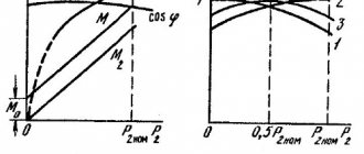
The U-shaped characteristics of the engine can be plotted using vector diagrams. More accurate results are obtained from vector diagrams taking into account saturation. U
-shaped characteristics for various values of
P
(or
M
) are presented in Fig. 7. As follows from a comparison of Fig. 6 and 7, when working with leading current, the motor is overexcited, and when working with lagging current, it is underexcited.
Rice. 6. Vector diagrams of an unsaturated non-salient pole motor at P = const
Rice. 7. Dependencies I = f ( IB )
and cos
φ = f ( IB )
for a synchronous motor at different values
of P(M)
: 1 - at
P 1 ( M 1 )
;
2 - with P
2>
P
1 (
M
2>
M
1);
3 - at P
3>
P
2 (
M
3>
M
2)
When overexcited, the engine generates reactive power directly from the consumer, which helps to increase cos φ
networks.
This makes it possible to reduce the reactive power generated by synchronous generators at power plants and reduce losses in power lines. The ability to generate reactive power distinguishes synchronous motors from asynchronous motors, which consume reactive power for excitation. Therefore, synchronous motors are designed to operate at rated power with overexcitation (with leading current) and cos φHOM
=0.9. Working with overexcitation is also preferable to increase the maximum engine torque.
In accordance with the given U
-shaped characteristics in Fig.
7 the dependences cos φ = f ( IB )
for various values
of
M. It follows that for any load on the shaft, synchronous motors can operate with different values of cos φ
, including cos
φ
=1. This is achieved by changing the current in the excitation winding.
4. Performance characteristics of synchronous motor
The performance characteristics of a synchronous motor can be obtained either with I
B=const, or with cos
φ
=
const
.
Figure 8 shows the performance characteristics of M, I
B,
P
1,
I
,
η = f ( P 2 )
under the condition
U = const
and cos
φ
= cos
φHOM = const
.
Rice. 8. Performance characteristics of a synchronous motor at cos φ
=
const
Dependence of torque on shaft M2≈M
from useful power is linear, since speed
ω 1 = const .
As follows from Fig. 7, to maintain cos φ=
const
with increasing load, the excitation current
I
B should be increased.
At idle ( P2 = 0
) the motor consumes active power from the network necessary to cover losses (mechanical and magnetic) inside the machine.
Therefore, when idling, the stator current will not be zero. As P2
P1
will increase , and therefore the current (where it includes both no-load losses - constant losses, and electrical losses in the armature winding).
Dependence of efficiency on P
2 is no different from that for other machines. Typically synchronous motors operate at a constant speed. If it is necessary to regulate the speed, a frequency method is used, in which the field speed and, consequently, the rotor speed are changed.
5. Starting a synchronous motor
A synchronous motor cannot be started by directly connecting the stator (armature) winding to the AC network.
This is explained as follows. When a multiphase armature winding is connected to the network, a rotating magnetic field is almost instantly formed, the rotation frequency of which is n
n depends on the frequency
f
of the current flowing through the windings (
n
n = 60
f
/
r
). The “poles” of this field, moving in space, will interact either with like or opposite poles of a stationary, excited rotor. In accordance with this, the direction of the torque acting on the rotor will change. During half the period of current change in the windings, the torque will be directed in one direction, and during the other half - in the opposite direction.
Starting could occur if the rotor accelerated to a steady speed during a half-cycle when the torque did not change its sign. At a frequency of 50 Hz, the half-cycle is 0.01 s. Due to mechanical inertia, the rotors of almost all synchronous motors will not be able to turn during this time.
There are several ways to start the engine. These methods consist in the fact that during the starting process the engine rotor accelerates to the speed of the rotating field, after which the engine enters synchronism
and starts working as synchronous. Applications include starting with an accelerating motor, frequency starting and asynchronous starting. Asynchronous starting is the most widespread.
Starting with booster motor
consists in the fact that an external (accelerating) motor turns the rotor of a synchronous machine to the rated speed. The field winding is connected to the DC network, and the stator winding is open-circuited. Then it is switched on for parallel operation with the network. After connecting the machine to the network, the accelerating motor is mechanically disconnected from the shaft of the synchronous machine, and the latter switches to motor mode. The power of the accelerating motor is small and amounts to 10-20% of the rated power of a synchronous motor. This power covers the power of mechanical and magnetic losses in a synchronous motor.
Frequency starting
is used if the synchronous motor is connected to an autonomous source, the voltage frequency of which can be changed from zero to rated. If you gradually increase the frequency of the supply voltage, the speed of the magnetic field will increase accordingly. The rotor, following the field, will gradually increase its speed from zero to nominal. During the start-up process, the machine operates in synchronous mode all the time.
Asynchronous start
similar to starting an asynchronous motor.
To do this, a starting winding is placed on the rotor in the pole pieces. This winding is made like a short-circuited rotor winding of an asynchronous motor and has the same device as the damper winding of a generator. At start-up, the three-phase stator winding is connected to the network. The current that will flow through this winding will create a rotating magnetic field. It will induce EMF and current in the starting winding of the rotor. As a result of the interaction of the rotor starting winding current with the rotating magnetic field, a torque is formed, under the influence of which the rotor will begin to rotate and rotate to a speed close to the field speed ω1
.
Its rotation will occur with sliding, which depends on the load on the shaft ( ω
<
ω1
).
Entering into synchronism is achieved after switching on direct current into the excitation winding due to the synchronizing torque that arises. From this time on, the machine begins to operate as a synchronous motor. In Fig. Figure 9 shows an asynchronous starting circuit. When starting, the field winding should not be open, since otherwise, due to the large number of turns in it, a large EMF would be induced by the rotating field, dangerous not only for the insulation, but also for the operating personnel. The field winding cannot also be short-circuited, since in this case it forms an asymmetrical (single-phase) circuit. It will cause the formation of an additional torque, under the influence of which there will be a dip in the mechanical characteristic curve near the semi-synchronous speed. Because of this, the rotor may get stuck at intermediate speed when starting (at point A
in Fig.
10). At the beginning of the start-up, the field winding LM
must be closed to a resistor with a resistance approximately 10-15 times greater than the resistance of the winding itself (switch position 1
S
).
At the end of the start, switch S
is moved to position 2, and the field winding is connected to the DC network.
Rice. 9. Scheme of asynchronous starting of a synchronous motor
| Rice. 10. Mechanical characteristics of the motor during asynchronous starting with a dip near semi-synchronous speed | Rice. 11. Mechanical characteristics of the motor with asynchronous starting |
Asynchronous starting of a synchronous motor is characterized by the values of the starting current I
P and torques—initial starting
M
P and input
M
B (Fig. 11). The input torque is an asynchronous torque at a rotor speed equal to 0.95ω1. This torque is equal to the highest load torque at which it is possible for the motor to enter synchronism when DC is switched on in the field winding.
If the network into which the synchronous motor is connected is not powerful enough, then in order to avoid a large voltage drop during asynchronous starting, measures are taken to reduce the initial starting current: switching on through an autotransformer, reactor, etc.
6. Synchronous compensators
The synchronous compensator is a source of reactive power and serves to regulate cos φ
networks. In terms of operating mode, it is a synchronous motor operating in idle mode, i.e., without mechanical load on the shaft. A synchronous compensator consumes active power equal to the losses inside the machine. To increase the efficiency of its operation, they try to reduce losses by using hydrogen for cooling, while due to the lower density of hydrogen compared to air, mechanical losses are reduced.
Rice. 12.U _
-shaped characteristic of a synchronous compensator
The most important characteristic of a synchronous compensator is U
-shaped characteristic (Fig. 12).
It differs little from the similar characteristic of a synchronous motor at P
2 = 0.
The reactive power developed by a synchronous compensator depends on the excitation current. An overexcited synchronous compensator operates with a current leading the network voltage and supplies reactive power to the network. When underexcited, it operates with a current that lags the network voltage and consumes reactive power from the network.
The synchronous compensator is switched on at the end of the transmission line directly at the consumer. By compensating partially or fully for the reactive component of the line current, it reduces the total current and losses in it.
Synchronous compensators are most often used in networks with large inductive loads to compensate for lagging current. Such a load is usually created by asynchronous motors connected to the network. In this case, the compensator works with overexcitation. In Fig. 13, 14 show the connection diagram of the GC
and vector diagram.
In the phasor diagram, current I
represents the current in the network in the absence of a synchronous compensator, and current
I
' represents the current in the network when it is turned on.
The reactive component I
P of current
I
is partially compensated by the current of the synchronous compensator
I
C, K. As a result, the angle between voltage
U
and current
I
' decreases, and cosφ ' increases.
In some cases, the synchronous compensator operates underexcitation. The need for this arises if the current in the line contains a significant leading component due to its capacitive reactance. This is observed during low-load hours of the transmission line, when the lagging load current does not compensate for the capacitive component of the line current.
Synchronous compensators are also installed to regulate the voltage at the end of the power line by regulating the reactive current and changing the voltage drop and its phase. With the leading current of the synchronous compensator, its excitation current is greater than with the lagging current, so the heating conditions of the compensator are more severe with the leading current.
Rice. 13. Connection diagram for a synchronous compensator
→
Rice. 14. Vector diagram for the current in the network with the synchronous compensator turned on
As a result, the rated power of the synchronous compensator is considered to be the power at leading current.
Synchronous compensators have some design differences from motors. They do not have an output shaft end; in addition, since the shaft does not transmit torque, it can be made thinner. Since the synchronous compensator is not required to provide large torque overloads, then M
Their MAX can be reduced by reducing the air gap (increasing
x
d). Reducing the air gap helps reduce the size of the field winding. All this leads to a reduction in the dimensions of the synchronous compensator.
Compensators are available in capacities from 2.8 to 320 MB∙A, usually in a horizontal design. Their rated voltages are 6.6-20 kV, and the rotation speed is 1000 or 750 rpm.
7. Test questions and homework.
| № | Content | Literature |
| 1 | Under what conditions does a synchronous machine operate in motor mode? | 3, §37-1 |
| 2 | Compare the vector diagrams of a synchronous machine (Fig. No. 2) for motor and generator operating modes? | 3 §37-1 |
| 3 | Define the losses existing in a synchronous motor? | 1, §37-2; 3, §35-2 |
| 4 | Write down the equations for electromagnetic power and electromagnetic torque of a synchronous motor, indicate the physical meaning of the quantities in the equations? | 2, §4-15 1, §37-2 |
| 5 | Compare the angular characteristics of a synchronous generator and a synchronous motor (Fig. No. 5)? | 1, §37-2; 2, §4-15 |
| 6 | How will the power factor cosφ change when the excitation current of a synchronous motor changes? | 3, §35-3; 1, §37-2 |
| 7 | What characteristics of a synchronous motor are called operating? | 2, §4-15; 1, §37-3 |
| 8 | Methods of starting a synchronous motor, give definitions and compare frequency and asynchronous starting? | 3, §37-1; 1, §37-2 2, §4-15 |
| 9 | Why, during the asynchronous start of a synchronous motor (Fig. No. 9), is its field winding shorted to resistor R? | 1, §37-4 |
| 10 | In what cases does a synchronous motor work as a synchronous compensator, its purpose, scope of application? | 3, §37-2; 2, §4-16 |
8. Literature
1. Tokarev machines. – M.: Energoatomizdat, 1990, 624 p.
2. Kopylov machines - M.: Logos, 2000, 607 p.
3. Woldek machines. – L.: Energy, 1978. – 832 p.
Synchronous compensators
Synchronous compensators (SC) are used to generate reactive power into the electrical network in order to increase the overall power factor, stabilize the standard voltage level in places where consumer loads are highly concentrated, reduce electricity losses and generally optimize the operation of energy systems.
Structurally, the compensator is a synchronous electric motor of lightweight design, operating in motor mode without active load, in other words, at idle, exclusively for generating reactive energy. Therefore, compensators installed at supply substations are often called reactive power generators. Among the most powerful reactive power receivers are asynchronous electric motors, which drive many mobile devices.
But during periods of decline in consumer loads, there is often a need to consume reactive power from the electrical network, since in such a situation the voltage in the network increases and in order to maintain its standard value it is necessary to load the network with inductive currents. For this purpose, all synchronous compensators are equipped with an automatic excitation regulator, which adjusts the value of the excitation current in such a way that the voltage at the compensator terminals remains practically unchanged.
Depending on the size and rated power, synchronous compensators have several types of excitation systems:
— electric machine excitation with sub-exciter;
Synchronous compensators are powerful electrical machines. The standard range of rated powers varies from 10-160 thousand kVA. The power factor varies between 0.92-0.95, while the number of poles is 8 or 6, which corresponds to a rotor speed of 750, 1000 rpm, respectively. They usually have a horizontal shaft design and are installed in substation rooms or in the open air. When installed externally, the housing of the compensators is sealed.
Compensators are produced with two types of cooling systems:
— air (for units with a rated power of up to 25 MVA);
— hydrogen (powerful fans are installed on the shaft to ensure intensive circulation of gas).
To perform asynchronous starting, synchronous compensators are equipped with starting windings; to start them, the reactor starting method is used, and in certain situations - direct.
The advantages of synchronous compensators include:
— the ability to smoothly automatically regulate the amount of reactive power;
— the possibility of increasing reactive power by increasing/decreasing the excitation current when the voltage in the electrical network decreases.
Source
Typical topologies of reactive power compensation circuits
Regardless of the type of reactive power compensation devices, two topologies for connecting them to AC power transmission networks with linear and nonlinear loads have become traditional at the moment:
- parallel (or transverse) reactive power compensation, in which the reactive power compensation device generated in parallel by a parallel network device does not depend on the voltage at the connection point.
Rice. Parallel (transverse) compensation of reactive power of an electric motor (inductive load): a - circuit without compensation, b - circuit with compensation
The advantages of parallel (transverse) reactive power compensation schemes include:
- independence of the generated reactive power from the voltage at the point of connection;
- possibility of smooth regulation of reactive power flow for compensation;
- effective stabilization of mains voltage.
The disadvantage of parallel (transverse) compensation is the limited ability to dampen rapid changes (oscillations) of the active component of power;
- series (longitudinal) compensation of reactive power, in which the device generating (or consuming during overvoltage correction) reactive energy is connected to the network in series and balances the reactance of the transmission line.
Rice. Parallel (longitudinal) compensation of reactive power of an electric motor: a - circuit without compensation, b - circuit with compensation. Rice. Typical diagram of a device for series (longitudinal) reactive power compensation with overvoltage protection
The advantages of sequential (longitudinal) reactive power compensation schemes are considered to be: the ability to optimize reactive energy flows across different voltage phases;
a significant degree of compensation; ease of integration into the network of compensating devices. The disadvantages of series (longitudinal) reactive power compensation are the lack of ability to regulate the mains voltage, the difficulty of controlling devices under variable loads, and the high risk of overvoltage during sudden load changes due to the device response delay.
Synchronous compensators
A synchronous compensator (SC) is a synchronous machine operating in motor mode without load on the shaft with a changing field current. In overexcited mode, the EMF of the stator winding E
K1 is greater than the network voltage
U
K (Fig. 2.25).
Under the influence of voltage difference DU= E
Kl
– U
I
appears in the stator SC , lagging behind the vector
DU
1 by 90°.
In this mode, the compensator supplies reactive power to the network. In underexcited mode E
K2
Rice. 2.26. Synchronous compensator type SWR:
1
– stator;
2
– rotor;
3, 4 –
insulating seals;
5
– fan;
6
– bearing;
7 – support platforms; 8
– oil pump;
9 –
slip ring chamber;
10 –
shaft;
11, 12 –
exit and entrance openings to the gas cooler;
The synchronous compensator is characterized by rated power, voltage, stator current, frequency and rated rotor current. The power scale is determined according to GOST 609–84. The rated voltage of the synchronous compensator is 5–10% higher than the rated network voltage.
Depending on the excitation current, a synchronous compensator can operate in overexcitation and underexcitation modes, generate or consume reactive power. The excitation current is regulated by special ARV circuits.
Low power synchronous compensators have an independent electric machine excitation circuit (see Fig. 2.9, a
)
,
On more powerful hydrogen-cooled machines (SWR), excitation is carried out from a special brushless exciter unit built into the compensator housing.
The AGP circuit of synchronous compensators is the same as that of generators.
Powerful SCs (10,000 kVA and above) are connected to the network through a reactor to limit starting currents and reduce voltage on the buses (Fig. 2.27). The reactor parameters are selected so that at the time of start-up the voltage on the substation busbars does not drop below (80 - 85 %
)
U
nom, and the voltage on the SC was (30 - 65
%
)
U
nom
,
while the current does not exceed (2 -2.8)
I
nom.
Rice. 2.27. Scheme of reactor start-up of a synchronous compensator
When starting, switch Q1
disabled,
Q2
enabled.
The compensator rotates due to an asynchronous torque. When the rotation speed approaches synchronous speed, excitation is applied and the compensator is pulled into synchronism. By adjusting the excitation current, the minimum stator current is set and switch Q1 is turned on,
bypassing the reactor and connecting the SC to the network.
Synchronous generators can operate in synchronous compensator mode if the access of steam (or water) to the turbine is closed. In this mode, an overexcited turbogenerator begins to consume a small amount of active power from the network and releases reactive power to the network.
Hydrogenerators are switched to synchronous compensator mode without stopping the units; it is enough to empty the hydraulic turbine chamber of water.
Source