Voltage parameters
Before you say that the voltage in your network does not meet the standard and file a claim with the energy supply organization, you need to know this standard. The voltage deviation range is set in normal mode: δUynorm= ± 5%, in the maximum permissible: δUylim= ± 10% of the nominal value.
In Russia, the rated voltage of the household network is Unom = 230 Volts (V), the upper range is 242 V. For Unom = 380 V, the upper range is 418 V. If the voltage is higher than these ranges and for this reason household appliances fail, you have the right to complain to the energy supply organization.
Overvoltage in apartment buildings
Recently, overvoltage in apartment buildings built before the early 90s has become a real disaster. When these houses were built, microwave ovens, refrigerators (two), computers, home solariums, etc. were not included in the design load.
But, nevertheless, consumers enjoy these benefits of civilization. What ends up happening? In the electric power industry there is a concept of evening and morning load peaks. It is at this time that people go to work, cook, turn on many electrical appliances in general.
burnout of the neutral conductor
If in normal mode the voltage between the phase and neutral conductors is 230 V, then in this case there is no neutral conductor and the voltage will be between the phases, i.e. 380 V. As a result, the voltage “walks” along the riser. Its value depends on the load connected to the network and can be in the range of 140 - 380 V from the point where the neutral conductor burns out.
Electricity industrial, static and atmospheric
All topics in this section:
Basic principles of state policy in the field of labor protection State policy in the field of labor protection is based on the principles: (8 principles STR-278 (scientific commentary) art. 4.) 1st principle - priority g
State financing of occupational safety measures · funds for the training of occupational safety specialists · scientific development · maintenance of the National Research Institute of Occupational Safety · maintenance of the network of government agencies
The rights of workers to occupational safety while working at an enterprise The Law “On Labor Protection” stipulates that each employee at the workplace is guaranteed in accordance with the requirements of regulations on occupational safety: · safety of technological processes
Benefits and compensation for difficult working conditions Employees engaged in work with difficult and harmful working conditions in the manner prescribed by law have the following benefits: · are provided with free medical and preventive
Labor protection of women and minors It is prohibited to use women's labor in heavy work and in work with harmful or dangerous working conditions, in underground work, except for some underground work (non-physical or sled work).
Management bodies of occupational safety in Ukraine State management of occupational safety is carried out by: · the Cabinet of Ministers of Ukraine (under the Cabinet of Ministers of Ukraine there is a National Council for the Safe Life of the Population); · Sovereign
Responsibility for violation of labor and occupational safety legislation According to Articles 18, 19 of the Law “On Labor Protection”, the employee is obliged to: · know and comply with the requirements of regulations on occupational safety; · know the rules and instructions for handling machines
Noise protection Noise is a disorderly combination of sounds of different levels and frequencies in the work area. Noise affects not only the hearing aid, but also causes disorders of the cardiovascular and nervous systems,
Protection from dust To protect the respiratory organs of workers from dust in the work area at industrial enterprises, the following measures are taken: · the air in the work area is cleaned by mechanical ventilation;
Combustion of a substance and methods of extinguishing it Types of combustion: explosion, flash, ignition, smoldering, self-ignition, combustion. By origin, fires are divided into: exogenous, arising from an external heat source (open
The concept of fire resistance Fire resistance is the ability of a structure or material to retard the spread of fire (fire), temperature, expressed in time (in hours). Buildings and structures are divided into five degrees of fire resistance
Electrical burns Electrical burns can be superficial or internal. Superficial burns - affect the skin. Internal burns - affect deep-lying organs and tissues of the body. By the mustache
Environmental factors Unfavorable environmental factors include industrial premises, open or outdoor electrical installations in the open air. Production premises by degree of danger
Personal protective equipment in electrical installations When operating electrical installations, to prevent electrical injuries, special personal protective equipment is used, which is divided into primary and auxiliary. Fixed assets
Warning notices, posters, devices Electrical protective equipment also includes warning portable posters and notices, which have their own specifics. Their purpose is to draw the attention of workers to immediate danger,
Prohibitory inscriptions and posters Poster size - 240 × 130 mm. Red letters on a white background. Contents of the inscriptions: “Do not turn on - people are working”, “Do not open - people are working”, “Do not turn on - people are working”
Grounding and protective grounding To protect people from electric shock due to insulation damage in a network with an isolated neutral and the transition of voltage up to 1000V to conductive parts of equipment, machines, machinery
Rules of behavior during a thunderstorm A person during a thunderstorm can be at work, on the street, at home, in the forest, in the field. In production, all buildings, structures, power lines, radios, communications are equipped with lightning devices
Ventilation and air condensation According to their purpose, ventilation and condensation systems are divided into working and emergency. Working ventilation is one that constantly creates the necessary meteorological
Annual medical examinations of minors To prevent occupational diseases - the normal development of youth, labor protection legislation establishes preliminary and periodic medical examinations. For persons under 18
Basics of Human Anatomy Every person should know the structure and functions of the body (anatomy and physiology). Anatomy (from Greek - dissection) studies the structure of the human body, its organs, tissues, and cells.
Basic quantitative indicators of the human body Blood volume: · for men - 5 liters; · for women - 4 liters. Heart rate: · 60-80 beats per minute. Blood pressure (ages 18-45):
First aid in case of electric shock The victim must be: · freed from live parts as quickly as possible; · quickly turn off the voltage with a switch or circuit breaker; · for release from live wires
Revival by methods of artificial respiration, indirect cardiac massage. The figure shows the correct position of the hands when performing external cardiac massage and determining the pulse in the carotid artery (dotted line).
Indirect (closed) cardiac massage External cardiac massage. If there is not only breathing, but also a pulse in the carotid artery, artificial respiration alone is not enough when providing assistance, since oxygen from the lungs cannot be transferred
Maximum voltage deviation in the electrical network
The current in the network is, for natural reasons, not constant and varies in certain parameters. Within the framework of the new 230 V/400 V standard, the nominal deviation is permissible within 5% and a maximum of no more than 10% should be observed in short-term intervals. Thus, such a theoretical deviation is allowed within 198 V and up to 242 V. This range can be considered relevant for most current apartments.
What affects network fluctuations in energy supply and voltage loss:
- One of the most common reasons is obsolescence of equipment, including meters, electrical panels, wiring cables, and so on;
- Significant errors are also observed in a poorly maintained network;
- Errors when planning and performing installation work in the house;
- Significant increase in energy consumption indicators exceeding the established standard.
As already noted, network fluctuations of +-5% are acceptable. So, for example, according to the supplied indicator of 220 volts, the permissible deviation in the network is equal to 209 V and the maximum excess is equal to 231 V.
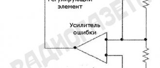
Mandatory voltage regulation in electrical networks
Carrying out your own voltage regulation is not only labor-intensive, but also requires financial investment. An even more difficult option is to seek stabilization of the current in the network from the supplier organization. This can be done by filing complaints, personal appeals, and lawsuits, however, the result is not always achieved even by these methods.
If you still decide to correct the picture yourself, then this is possible in the following way:
- Method of centralized voltage regulation. This approach involves calculating how many changes will be needed to stabilize the situation and adjusting the central power supply accordingly.
- Linear impact method. This is done using a so-called linear regulator, which changes the phases using a secondary winding on the circuit.
- Use of capacitor banks in the network. This method is theoretically called reactive power compensation.
- Also, an extremely unstable network can be corrected using longitudinal compensation. It involves connecting capacitors in series to the network.
Another relevant option, if the deviation from the established norm is not too pronounced, is to install one large or several small stabilizers in the network. This will require some financial investments, special installation skills, and is also not suitable for highly fluctuating power supply systems, because they simply cannot do a large amount of work and regulate a large amount of voltage.
So, as has already been determined, the new generally accepted standard is the network voltage in an apartment from 230 V to 400 V. For example, the voltage scale can be 240 V, 250 V, taking into account the maximum permissible error. However, for the e1f outlet we are used to, the operating voltage is still the same 220V level, which has been familiar to us all since the Soviet period.
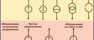
Why AC voltage?
Not so long ago, by historical standards, humanity had a dilemma: which current is better? Variable or constant? This period of time was known as the "War of the Currents." In fact, there were disputes between Nikola Tesla and Edison, the greatest scientist-inventors of the time. Edison was for direct current, and Nikola Tesla was for alternating current. This struggle continued for more than 100 years, even after the death of these great scientists! But still, in 2007, alternating current won the final victory.
The thing is that direct current, when transmitted over long distances, loses its energy by heating the wires. The Joule-Lenz law is to blame here
Q=I2Rt
Where
Q - amount of heat generated (Joules)
I - current flowing through the conductor (Amps)
R - conductor resistance (Ohms)
t - time of passage of current through the conductor (Seconds)
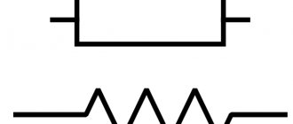
It is not difficult to guess that the more current flows through the wires, and the longer the wires are, the more they will heat up, since the resistance of the wire is expressed by the formula:
wire resistance formula
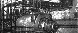
The second reason was that the DC generator had to use a special design that would allow the removal of electric current from moving windings. To do this, a so-called commutator , to which the generator windings were soldered. The collector was in motion all the time, since it was fixed to the generator shaft itself. The voltage was removed from the commutator using graphite brushes. The same principle is still used in generators and DC motors.
Operating principle of a DC generator
The disadvantage of this design is that over time the brushes and commutator wear out. Therefore, such a generator must be serviced frequently, the brushes must be replaced on time and the commutator must be cleaned. Most often, such a generator has two wires: plus and minus. The more collector plates (lamellas) on such a generator, the cleaner the direct current from such a generator will be. If such a generator has many lamellas and rotates at the same speed, then on an oscilloscope you can see something like this picture of direct current
DC waveform
An alternating voltage generator does not have such disadvantages. Its operating principle is shown below
Working principle of alternator
Currently, it uses three windings spaced 120 degrees apart. One end of each winding is connected to each other, forming the so-called “zero”. In our country, they try to spin such generators at thermal power plants or hydroelectric power stations at a speed of 50 revolutions/sec. Well, or 3000 rpm. That's not a bad speed.) In America, they are turned at 60 rpm. What are revolutions per second? This is the frequency. And frequency, as you remember, is expressed in Hertz (Hz). Therefore, in our sockets the frequency is 50 Hz, in America it is 60 Hz.
Such generators are called three-phase, since they have three phases: A, B, C. In English literature you can see the designation R, S, T or L1, L2, L3. The point where the end of all windings is connected is designated by the letter N (zero).
Alternator
That is, in fact, 4 wires come out of the generator: phases A, B, C and 0, also known as neutral N, which connects one end of each of the three windings.
Alternator windings
When the rotor-magnet rotates, an electric current is created in each winding. If you use an oscilloscope to display oscillograms of three windings at once, you can see something like this:
Three-phase voltage oscillograms
Full voltage standards in the electrical network: GOST
Despite the fact that the majority of ordinary people and people who do not belong to the category of knowledgeable in the field of voltage in their electrical network will affirmatively say that the standard voltage is 220 V. To their surprise, even despite the old and familiar stickers, on which indicates the generally accepted standard are no longer relevant.
Such acts have also been adopted in Ukraine and the Baltic countries, including Belarus.
What did the change in standard lead to:
- The operating voltage on the power cable has changed;
- Fluctuations have become a little more significant than before, but still within the acceptable limits of 5% and the maximum – 10%;
- The potential payment for electricity supply services has not increased by a completely symbolic amount;
- Voltage supply frequency – 50 Hz.
Thus, the network voltage should be considered slightly increased in everyday practice. But in reality, everything is different, and this promises the presence of pitfalls in the supply of electricity to organizations. Despite the generally accepted standard, organizations supplying voltage to apartments in houses supply everything according to the same standards adopted back in Soviet times and equal to 220 V. All this happens officially in accordance with GOST 32144-2013, which is what suppliers are guided by.
The Role of Input Common Mode Voltage Range in Op-Amp Selection
Input common-mode voltage range is an important parameter for operational amplifiers (op-amps). The article discusses options for the operation of an amplifier when the input signal goes beyond its scope.
The main parameters when selecting an op-amp model are the supply voltage, the product of the gain and the bandwidth, the rate of rise of the output voltage, and the input noise voltage. However, equally important is the input common mode voltage range - a key parameter for any op amp, neglecting which can lead to unpredictable behavior of the amplifier. Perhaps many have dealt with a situation where the output signal of an op-amp was not as expected. The cause of unwanted signals at the output could be an incorrect selection of values in the output stage. For example, too much output capacitance may cause pulses to oscillate or clip before they reach their maximum amplitude if the output stage's signal swing is less than the maximum supply voltage. Strange behavior at the op-amp output may be associated not with the output stage, but with the input stage, if the input signal is outside the range of the input common-mode voltage.
| Rice. 1. Finding the input common mode voltage |
The input common mode voltage VICM is one of the most important parameters of the input stage. It characterizes the average voltage value at the inverting and non-inverting inputs (see Fig. 1): VICM = [VIN++VIN–]/2. Another way to determine the input common mode voltage is to find the common voltage level for the interting and non-inverting inputs VIN+ and VIN–. In most circuits, VIN+ is very close to VIN– because negative feedback causes the voltage at one pin to closely follow the voltage at the other. This definition is valid for common-mode circuits, including voltage followers, inverting and non-inverting circuits. In these cases, take VIN+ = VIN– = VICM. Another parameter characterizing the input of the op-amp is the range of the input common-mode voltage VICMR. As a rule, it is always indicated in technical documentation and is of paramount importance for developers. The input common-mode voltage range characterizes the voltage values at which the op-amp operates correctly, and also shows how close the input signal can be to the supply voltage:
VICMR = VICM R_MAX - VICM R_MIN,
where VICM R_MIN is the limit with respect to the negative supply voltage VCC–, VICM R_MAX is the limit with respect to the positive supply voltage VCC+. (see Fig. 2). When the voltage exceeds this range, the amplifier may enter nonlinear mode.
| Rice. 2. VICM R definition |
Note that the designations VICM and VICM R introduced above are not generally accepted and can be chosen arbitrarily by the manufacturer (the most common options are VCM, VIC and VCMR).
VICMR
The characteristics of the amplifier input stage depend on the technology used (CMOS, BPT, field-effect transistors with control pn junction). Table 1 shows examples of Texas Instruments amplifiers. The column “maximum supply voltage range” shows restrictions for cases of unipolar and bipolar supply voltages. It can be seen that all amplifiers have different ranges of input common-mode voltage, and it can be either greater or less than the supply voltage swing. Accordingly, the value of this parameter must always be taken from the technical documentation.
Table 1. Examples of Texas Instruments amplifiers
| Name | Technology | Max. supply voltage: bipolar/unipolar, V | VICM RMIN, V | VICM RMAX, V |
| TLE2062A | JFET input | ±19/38 | (VCC−)+3.4 | (VCC+)−1 |
| TLC2272 | LinCMOS | ±8/16 | (VCC−)−0.3 | (VCC+)−0.8 |
| TL971 | BiCMOS | ±7,5/15 | (VCC−)+1.15 | (VCC+)−1.15 |
| OPA333 | CMOS/rail-to-rail input | ±2,75/5,5 | (VCC−)−0.1 | (VCC+)+0.1 |
| OPA735 | CMOS | ±6/12 | (VCC−)−0.1 | (VCC+)−1.5 |
Op-amps whose input signal has a supply voltage swing (rail-to-rail) deserve special attention. Despite the name, not all amplifiers in this class can handle the full supply voltage range. It is necessary to check the technical documentation.
Examples of misuse
As a rule, the output behind VICMR is found in circuits with a single-polar power supply (SP) of 3.3 V, 5 V or other low value. In such circuits the input voltage range is usually narrow. If the signal does not fall into it, the op amp's output may experience unwanted effects such as clipping below the expected level, voltage shift, phase change, or reaching the supply voltage prematurely. Let's look at some examples of incorrect operation to understand the dangers of not complying with VICM R. Let there be two op-amps with different VICMRs and an output signal equal to the supply voltage swing. Figure 3 shows a circuit with a unipolar power supply. Measurements are carried out in laboratory conditions at room temperature of about 25ºС. Let's consider the TLC2272 op-amp with VCC = 10 V. The documentation indicates that VICMR is: –0.3...4.2 V at a supply voltage of 5 V and an ambient temperature of 25ºC. Note that the input signal range is close to the supply voltage 0.8 V below VCC. For our case, accordingly, the upper limit of the input voltage will be about 9.2 V. Let us apply a sinusoidal signal with a frequency of 300 Hz and a constant component equal to half VCC to the input, i.e. 5 V. We adjust the variable component so that changes appear at the output. When there is a peak value of 10 V at the input, we see a signal at the output that is cut off in the region of the positive supply voltage, and not the negative one. This is the result of the input signal exceeding 9.2 V. When the input voltage is 0...9.2 V, the amplifier operates correctly (see Fig. 4).
| Rice. 3. Amplifier with unipolar power supply |
| Rice. 4. Cutting off output pulses when exceeding 9.2 V at the input |
Consider a voltage follower circuit with an output signal equal to the supply voltage swing. Let the circuit be powered by a single 5V supply. The documentation says that the VICMR is 1.15 to 3.85V, or approximately 2.7V, with a DC component of VCC/2. Let's apply a sinusoidal signal with a frequency of 1 kHz and a constant bias of 2.5 V. We increase the amplitude of the input signal from 200 mV until the output signal changes. With an input signal amplitude of 2.7 V, the output signal is linear. We continue to increase the input signal to 3.5 V. The linear operating mode is maintained. Note that this exceeds the characteristics stated in the documentation. As soon as the signal slightly exceeds 3.52 V, the output (see Fig. 5) exhibits nonlinear behavior at both supply voltage limits (0 and 5 V). We continue to increase the amplitude of the input signal. As soon as it approaches the maximum value of the supply voltage (see Fig. 6), a jump appears in the output signal, and it does not change until the input signal reaches an acceptable value. If the input signal crosses the lower limit, a phase shift occurs at the amplifier output. The output voltage takes the average level, 2.5 V, and follows the input signal until it is within the acceptable range again.
| Rice. 5. Nonlinear operation at VIN = 3.52 V |
| Rice. 6. Output signal at VIN = 4.2 V |
The considered examples show that the amplifier's response to exceeding VICMR can be different, it all depends on the type of op-amp. Let's do one more experiment. Let's apply a constant voltage to the input of the circuit in Figure 3. By changing its value, we obtain output results similar to the above, but with the difference that the signal does not change over time. Depending on the type of circuit, when evaluating an amplifier, a constant or variable signal, or a combination of both, is used.
Solution
Sometimes it turns out too late that the selected amplifier does not meet the VICMR requirements. If it is no longer possible to replace the op-amp, you can try to solve the problem in several ways. First, if the amplitude of the input signal is very large, a resistive divider should be used to keep the input signal within the allowed range. If the problem is offset of the input signal, you can use a bias circuit to move it within the acceptable range. Finally, sometimes it is enough to replace the amplifier with an op-amp with an input signal swing equal to the supply voltage swing. The input common-mode voltage range is the most important parameter when choosing an op-amp. If you choose it correctly from the very beginning, you can avoid problems in the future.
Literature
1. OPA333 1.8V, 17μA, microPower, Precision, Zero Drift CMOS Op Amp//Texas Instruments, May 2007, https://bit.ly/jjLQ8o. 2. TL971 Output Rail-to-Rail Very-Low-Noise Operational Amplifier//Texas Instruments, December 2009, https://bit.ly/iuIPzQ. 3. TLC2272 Dual Low-Noise Rail-To-Rail Operational Amplifier//Texas Instruments, May 2004, https://bit.ly/jCCutr. 4. Tina-TI SPICE-Based Analog Simulation Program//Texas Instruments, Aug 21, 2008, https://bit.ly/mrl0ay.
GOST 29322-92. Standard voltages
Of all the former republics of the USSR, Russia, Ukraine, and the Baltic countries switched to the “230V” standard.
It should be understood that electrical equipment manufactured in Russia and for Russia must operate normally at both 220V and 230V. As a rule, devices have a voltage range from -15% to +10% of the nominal voltage.
Geography of countries with standard voltages: 100V, 110V, 115V, 120V, 127V, 220V, 230V, 240V
Different countries around the world have adopted different mains voltage standards. You can find the following standards: - 100V in Japan, - 110V in Jamaica, Haiti, Honduras, Cuba, - 115V in Barbados, El Salvador, Trinidad, - 120V in the USA, Canada, Venezuela, Ecuador - 127V in Bonaire, Mexico, - 220V in many countries in Asia and Africa, - 230V in many countries of Europe and parts of Asia, - 240V in Afghanistan, Guyana, Gibraltar, Qatar, Kenya, Kuwait, Lebanon, Nigeria, Fiji
Geography of countries where voltages of 220V and 230V are accepted
The most widely used standards are 220V and 230V; these standards are accepted in more than 150 countries around the world.
In practice, of course, the network voltage is constantly changing and depends on many factors. Often the permissible voltage range is indicated on the back of the product or on the electrical plug of the device. The most demanding in terms of power quality are devices that have electric motors (refrigerators, air conditioners, washing machines, heating boilers, pumps). It is clear that for any devices used in Russia, both 220V and 230V voltages are good.
What are the deviations in power quality? It is well known that our networks often have significant deviations from power quality standards. And the voltage can be significantly lower than 220V or significantly higher than 230V. The reasons for this phenomenon are also known: aging of existing electrical networks, poor maintenance of networks, high wear and tear of network equipment, errors in network planning, and a large increase in electricity consumption. Problems in networks include: low and low voltage, high and high voltage, power surges. voltage dips, overvoltage, change in current frequency.
There is a solution to the problem! And every lover of country life has the right to provide himself with stable voltage using our equipment. We are waiting for your questions and comments by email. email [email protected]
5 reasons to buy a stabilizer from us
- urban comfort in your countryside, thanks to the stable operation of all electrical equipment
- consultation from our professional engineers to solve your specific problems
- warranty on our equipment is 3 (three!) years
- free delivery directly to you within the city
- installation of equipment by a professional electrical engineer
What is the network voltage
Since 2003, a standard voltage of 230V should have appeared in the sockets of our apartments and private houses. But for the past 17 years this transition has not been completed.
From September 30, 2014, instead of GOST 29322-92, GOST 29322-2014 (IEC 60038:2009) was adopted, establishing what the standard voltage should be in Russia. Now its value is 230 V (±10%) at a frequency of 50Hz (±0.2). But still quite often there is 220 V in the electrical network instead of the expected 230 V.
The rated parameters of AC power networks up to 1000 V are indicated in the table given in GOST 29322-2014.
In the first and second columns, the smaller values are the voltage between phase and neutral (phase), the larger values are between phases (linear). If one value is specified, it is the voltage between phases of a three-phase three-wire system.
The standard voltage of 230/400 V appeared as a result of the evolution of the 220/360 V and 240/415 V systems. Currently, the 220/360 system is no longer used in Europe and other countries, but 220/380 V and 240/415 V are still actively used.
The change in standards was caused by the need to bring electricity into full compliance with European parameters to facilitate the export and import of electricity and electrical devices.
Where does the voltage come from?
To supply electricity to an outlet, it must be generated somehow. To generate electricity, technologies from the late 19th century are still mostly used - electromagnetic induction, which converts mechanical energy into electrical energy. In other words, generators. The difference between generators is only in how mechanical energy is supplied. Previously, these were bulky steam engines. Over time, hydraulic turbines for running water (hydroelectric power stations), internal combustion engines, and nuclear reactors were added.
The operating principle of the generator is based on magnetic induction. The rotational movement of the generator is converted into electric current. That is, we can say that a generator is the same electric motor, but of reverse action. If voltage is applied to the electric motor, it will begin to rotate. The generator works in reverse. The rotational movement of the generator shaft is converted into electric current. Therefore, in order to rotate the generator shaft, we will need some kind of external energy. It could be steam that spins the turbine, which in turn spins the generator shaft
Operating principle of thermal power plants
or it can be the force of the water flow, which, with the help of a hydraulic turbine, spins the generator shaft, and it, in turn, also generates electric current
Operating principle of hydroelectric power station
Well, or it could even be a windmill
Wind power plant
In short, the principle is the same everywhere.
By the way, a nuclear reactor is not capable of generating energy on its own. In fact, a nuclear power plant is the same primitive steam boiler, where the working fluid is ordinary steam. Yes, today there are other ways to generate electricity, such as the same solar cells, beta-galvanic and isotope nuclear batteries, “mythical” tokomaks. However, the above-mentioned “high-tech” has significant limitations - the prohibitive cost of materials, installation and setup, dimensions and low efficiency. Therefore, it is not worth seriously considering all this as a full-fledged high-power power plant (at least in the next couple of decades).
Voltage drop in the home network
The so-called voltage drop can be fraught with many undesirable consequences. Moreover, it is undesirable both by the residents themselves and by the supplier organization, because it will be the one who will cover all unforeseen expenses. For objective reasons described earlier, power outages can reach record levels.
If there is no desire to correct the defects, this is grounds for filing a claim in court.
What are the consequences of exceeding or significantly reducing the established norms for voltage supply in the house:
- Light bulbs burn out faster;
- This is especially harmful for a refrigerator, washing machine and other electrical household appliances that require powerful and constant voltage;
- The service life of any electrical equipment, including microwaves, toasters, TVs, computers, and so on.
Thus, it becomes obvious that all classes of electrical engineering suffer from severe voltage fluctuations. This influence is especially destructive if the network voltage is low. And the obligation to provide uninterrupted, stable and high-quality current belongs to the organization that supplies it and, according to the contract, must ensure its high-quality service.
How much do you need for electrical appliances?
Equipment manufactured in Russia for domestic consumers operates at both 220 V and 230 V, because manufacturers provide the required margin from -15% to +10%. from face value. But in each specific case, the permissible range of power supply characteristics for the device is indicated in the product passport or on its label. For example, computers can operate at 140 - 240 V, and a telephone charger at 110 - 250 V. These markings are often applied to the product itself.
Devices with electric motors are most sensitive to power quality. Here, a reduced voltage can lead to difficulties in starting and shortening the service life of the equipment, while an increased voltage will lead to overloads, which also shorten the service life. If you take a regular incandescent lamp and lower the supply voltage by 10%, the glow intensity will noticeably decrease, and if you increase it, its service life will be reduced by 4 times.
The permissible maximum network limit is 253 V. This value may be too high for electrical equipment designed for 220 volts. The difference in voltage will lead to overheating of power supplies, network adapters, and premature failure of devices.
If you notice that your equipment has begun to overheat or break down, check the voltage in the network. If a deviation of more than 10% is detected, immediately contact your network company. They are required to take measures to eliminate the factors that caused the violations.
Now you know what the voltage standard in the Russian network is according to GOST. If you have any questions, ask comments under the article. We hope the information was useful and interesting for you!
Amount of permissible voltage drop: PUE
According to the accepted rules for the design of electrical installations (PUE) back in the former USSR, a voltage drop is the difference in voltage levels at different points of the network. As a rule, these are the starting and ending points of the chain. In established standards, the law requires a distinction between the concepts of voltage deviation and voltage loss. If the first case, on a generally accepted scale, is considered using the example of an incandescent lamp, the deviation indicator of which is recognized as nominal and mandatory, then in the case of the loss considered on the station buses, this is recognized as a recommended indicator.
Normal voltage drop in the network:
- In so-called overhead lines – up to 8%;
- In cable power supply lines – up to 6%;
- In networks of 220 V - 380 V - in the region of 4-6%.
In this case, a drop in the emergency mode is considered to be a drop of up to 12% in the network - this is the established limit. A fall above the established norm promises the activation of the automatic protective system, which should be activated when the lower norm is reached for at least 30 seconds.
Also in some sources you can find voltage standards that exceed even the new indicators of 230 V and 400 V. Do not confuse examples of domestic use with a plant or factory, where the indicators naturally significantly exceed the domestic environment.
Transmission of electric current over long distances
So, we have received an electric current. Now we need to somehow transmit it over long distances, not forgetting about the Joule-Lenz law: Q=I2Rt. That is, we need to somehow miraculously reduce the current that will flow through the wires, since it is mainly responsible for large losses.
A transformer is ideal for these purposes, but not a simple one, but a three-phase one. This uses a remarkable property of a transformer: if we increase the voltage, then we lower the current, and vice versa, we lower the voltage and increase the current. Therefore, in order to transmit the received electricity over long distances, we need to increase the voltage several times, thereby reducing the current strength by the same number of times. Below in the figure is a diagram of the transmission of electricity from a hydroelectric power station generator to the end consumer, that is, for factories, for electric vehicles and for you and me.
Transfer of electricity from the generator to the final consumer
With hydroelectric power plants, the voltage is increased to several kilovolts, most often to 110 kV. All this is achieved using a three-phase high-voltage step- up transformer (2).
Three-phase high voltage transformer
Next, the high-voltage voltage travels along the high-voltage line (3) and reaches a city or regional center.
High voltage power transmission line
Each regional center or city has its own substation, which already has its own high-voltage step-down transformer (4), which converts a voltage of 110 kV into 10 kV, or 6 kV (5).
Why couldn’t it be possible to immediately pull the wires from the generator? Why was it necessary to increase and then decrease the voltage again? All again due to the Joule-Lenz law. Since the hydroelectric power station is located at a very large distance from electricity consumers, it is necessary to increase the voltage in order to minimize losses due to heating of the wires. As we have already said, the transformer increases the voltage, but at the same time reduces the current strength by the same amount, so losses in wires over long distances are reduced significantly, based on the Joule-Lenz formula Q = I2Rt.
Then, from the substation, the voltage is distributed to transformer “booths”, which can already be seen in every area.
Transformer 6 kV to 380 V
From these “booths” approximately 380 Volts comes out after conversion. But there is one nuance here. Three wires are used everywhere, but most often two wires enter our houses. What's the matter? But the point is that there is such a thing as linear and phase voltage. Line voltage is measured between 3 wires carrying 380 V. They are called phases. That is, roughly speaking, these are the same wires that came out of the generator somewhere else at the hydroelectric power station. But if we take any of the phases and measure the voltage relative to the neutral conductor, that is, relative to zero, then we will have a phase voltage of 220 V. It turns out that ONE phase and ZERO comes into our house. Where do the other phases go? They are evenly distributed among the residents of the house or your area. That is, a different phase may come to your neighbor, but the same zero.
Three-phase power transmission line