Super or ultracapacitors, also known as high-capacity capacitors, store energy electrostatically by polarizing an electrolyte solution. The energy storage process in a supercapacitor does not involve chemical reactions, although a supercapacitor is an electrochemical device. High-capacity or supercapacitors can be charged and discharged thousands of times due to the highly reversible energy storage mechanism. A supercapacitor is an electrochemical capacitor that has the ability to store an extremely large amount of energy, relative to its size and compared to a traditional capacitor. This property of a supercapacitor is of particular interest to the automotive industry in the production of hybrid vehicles, as well as in the production of battery-electric vehicles, where the supercapacitor is used as an additional energy storage device.
Types of supercapacitors
Properties of supercapacitors
Among the properties it should be noted:
- Highest capacity density
- Lowest cost per farad
- Reliable, long service life
- High cycle efficiency (95% and above)
- Uninterrupted operation
- Environmental safety
- Wide operating temperature range
- High specific power and fairly high specific energy
- Very high charge/discharge speed
- A large number (thousands) of cycles with minor degradation of parameters
- Good reversibility of the energy storage mechanism
- Reduced toxicity of the materials used
- Low equivalent series resistance (ESR)
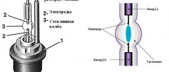
Supercapacitors, whose capacitance comes from their double-layer structure, store energy in a polarized liquid layer just a few angstroms thick located at the interface between an ionic-conducting electrolyte solution and an electronically conducting electrode. According to experts in this field, for example, Mr. Kahlert, supercapacitors should be considered capacitors with a capacity of at least 10 farads. Supercapacitors are predominantly double-layer capacitors; Capacitors made using other technologies, for example, film or ceramic, are not considered supercapacitors. Typically, in a supercapacitor, two active electrodes, separated by a porous non-conducting material, are placed between two metal current collectors. The electrolyte, aqueous or organic, impregnates the porous electrodes and ensures the emergence of charge carriers with subsequent accumulation.
A supercapacitor is typically used to provide pulsed or peak power to a device. A supercapacitor is also used to supply short-term energy to devices and to absorb energy from its application area. An example of peak power application is power lines, an example of short-term energy supply is cell phones/consumer electronics and radios, and an example of energy absorption is regenerative braking devices in hybrid/electric vehicles.
Classic supercapacitor operating principle
Supercapacitors, also known as EDLC (electrical double layer capacitors), contain two metal plates coated with a porous material (activated carbon) and can store significant amounts of energy. They are immersed in an electrolyte of positive and negative ions found in a solvent. One plate is positive and the other is negative. During charging, ions from the electrolyte accumulate on the surface of each carbon-coated plate.
In addition, supercapacitors also store energy in the electric field that is formed between two oppositely charged electrodes, since there is an electrolyte in which an equal number of positive and negative ions are evenly distributed. Thus, during charging, each electrode has two layers of charge coating (electrical double layer).
During the charging of the supercapacitor, ions from the electrolyte not only accumulate on the surface of each carbon-coated plate, but are also stored in the electric field. Thus, during charging, each electrode has two layers of charge coating
Applications of supercapacitors
Applications of supercapacitors can be classified based on existing and potential applications. Emerging applications include: storage devices for renewable energy sources such as solar, wind and ocean wave, fuel cells; vehicles such as hybrid electric vehicles, engine starters for conventional gasoline vehicles, train locomotives and hydrogen fuel vehicles. Supercapacitors can also be used as energy storage devices in the residential sector, for example in houses with solar photovoltaic systems, where storage devices other than conventional batteries are required. Promising areas of application in the near future include the military, aerospace and medical industries.
Due to their high specific capacitance and energy density, supercapacitors are used as a short-term power source in electronic devices. They are also very widely used in uninterruptible power supply systems (UPS). The advantage is that they provide instant power in critical applications. Emerging applications for supercapacitors include short-term parallel power supply for stationary uninterruptible power supply systems with fuel cells. They are particularly suitable for use in engine starting devices and also in peak load damping devices.
Existing applications include critical load power generation (utility grids), hospitals, banking centers, wireless towers, and airport communications. Supercapacitors provide critical loads within seconds or even milliseconds. They are most widely used in the consumer electronics market as a backup power supply for storage devices, microprocessors and motherboards. In the consumer electronics market, supercapacitors are used in increasing numbers in mobile phones.
Kinds
A supercapacitor is the same battery, but with an order of magnitude better properties. This primarily relates to significantly faster charging and discharging. A supercapacitor is an element with two electrodes, with an electrolyte located between them. The electrodes are made in the form of a plate of a certain material. To improve the electrical parameters of a supercapacitor, the plates can be additionally coated with a porous material, for example, activated carbon. An inorganic or organic substance can be used as an electrolyte.
In general, a supercapacitor is a hybrid of a chemical battery and a conventional capacitor:
- The main difference between a supercapacitor and a conventional capacitor is that the former has not just a dielectric between the electrodes, but a double electrical layer. As a result, a very small distance is formed between the electrodes, and its ability to accumulate electrical energy (electrical capacity) is much higher.
- In addition, a supercapacitor from a battery differs in the rate of accumulation, as well as the degree of release of the electric charge. Thanks to the use of a double electrical layer, the surface area of the electrodes is increased with the same overall dimensions. That is, the device combines the best electrical characteristics - significant battery capacity and capacitor speed.
People first started talking about a supercapacitor in 1962. It was then that a chemist at the American Standard Oil Company, Robert Reitmeier, filed a patent application detailing the mechanism for storing electrical energy in a capacitor that had a “double electrical layer.” In the proposed version, the emphasis was on the material of the linings. The electrodes must have different conductivities: one electrode must have electronic conductivity, and the other - ionic conductivity. As a result, when the capacitor was charged, the separation of positive centers and electrons in the electronic conductor, as well as the separation of anions and cations in the ionic conductor, occurred.
In 1971, the license went to the Japanese company NEC, which by that time was involved in all areas of electronic communications. NEC was able to successfully promote a technology called "Supercapacitor". Then other companies began to develop supercapacitors. Since the 2000s, active development of technology began in many countries around the world.
Supercapacitors today are divided into:
- Double layer capacitors (DSC).
- Pseudocapacitors.
- Hybrid capacitors.
A double-layer supercapacitor involves the presence of two porous electrodes made of electrically conductive materials, and also separated by a separator filled with electrolyte. Here, the process of energy storage occurs due to charge separation on electrodes with a very large potential difference between them. The electrical charge of double-layer capacitors is determined directly by the capacitance of the double electrical layer, that is, a separate capacitor on the surface of each electrode. They are connected to each other in series through an electrolyte, which is a conductor with ionic conductivity.
Pseudocapacitors are already closer to rechargeable batteries. They have two solid electrodes. The operating principle combines two energy conservation mechanisms: Faraday processes, which are similar to the processes occurring in batteries and accumulators, as well as electrostatic interaction, characteristic of capacitors with an electrical double layer. The prefix “pseudo” appeared due to the fact that the capacity of the EDL depends not only on electrostatic processes, but also on fast Faraday reactions with charge transfer.
Hybrid capacitors are a transition option between a capacitor and a battery. The word “hybrid” is due to the fact that the electrodes in hybrid capacitors are made from different materials, and charge accumulation is carried out by different mechanisms. In most cases in hybrid capacitors, the cathode is a pseudocapacitance material. As a result, charge is accumulated at the cathode due to redox reactions, which increases the specific capacitance of the capacitor and also expands the range of operating voltages.
Hybrid capacitors often use a combination of doped conducting polymer and mixed oxide electrodes. Composite materials that consist of metal oxides deposited on conductive polymers or carbon supports may become very promising.
Operating principle
Supercapacitors, as high-capacity capacitors, store energy electrostatically by polarizing an electrolyte solution. When storing energy in a supercapacitor, no chemical reactions are involved, although the supercapacitor is an electrochemical device. Due to the high reversibility of the energy storage mechanism, capacitors are capable of being charged and discharged thousands of times.
A supercapacitor is an electrochemical capacitor that has the ability to store an extremely large amount of energy relative to its size and also in comparison to a traditional capacitor. This property of a supercapacitor is especially interesting in the creation of hybrid vehicles in the automotive industry, including the production of battery-electric vehicles, in which supercapacitors are used as an additional energy storage device.
In most cases, a supercapacitor has two active electrodes, which are separated by a non-conducting material placed between metal current collectors. An organic or aqueous electrolyte impregnates the porous electrodes, ensuring the appearance of charge carriers in the device and its subsequent accumulation.
Applications and Features
Application areas of supercapacitors can be divided into the following areas:
- Storage devices for renewable energy sources such as fuel cells, ocean wave, wind and solar.
- Vehicles, e.g. car starters, hybrid electric vehicles, hydrogen fuel vehicles, train locomotives.
- As energy storage in the residential sector, for example in buildings with solar photovoltaic systems, where there is a need for batteries with improved performance.
- Due to their high energy density and specific capacitance, supercapacitors are used in electronic devices as a short-term power source.
- In uninterruptible power supply systems. The advantage is that they provide instantaneous power in critical applications.
- Among the emerging areas, supercapacitors are finding applications in fuel cell uninterruptible power systems.
- In peak load damping devices, as well as engine starting.
- Power generation with critical loads, airport communications, wireless communication towers, banking centers, hospitals.
- Backup power supply for motherboards, microprocessors and storage devices.
- Cell phones.
Advantages and disadvantages
Among the advantages of supercapacitors are:
- Low cost of energy storage device per 1 farad.
- Highest capacity density.
- High cycle efficiency, which reaches 95% and above.
- Long service life.
- Device reliability.
- Environmental Safety.
- Trouble-free operation.
- Very high specific energy and specific power.
- Wide operating temperature range.
- A large number of cycles with practically unchanged parameters.
- High charge and discharge speed.
- Reduced toxicity of the materials used.
- Excellent reversibility of the energy storage mechanism.
- Acceptability of discharge to zero.
- Light weight compared to electrolytic capacitors.
Among the disadvantages of supercapacitors are:
- Relatively low energy density.
- Inability to provide sufficient energy storage.
- Very low voltage per element unit.
- High degree of self-discharge.
- Insufficient development of technology.
Ionistors, supercapacitors, ultracapacitors - the history of the creation and development of technology
On June 7, 1962, Robert Rightmyer, a chemist for the American Standard Oil Company (SOHIO), located in Cleveland, Ohio, filed a patent application detailing a mechanism for storing electrical energy in a capacitor having an “electric double layer.” If in a conventional capacitor the aluminum plates were traditionally insulated with a layer of dielectric, then in the version proposed by the inventor the emphasis was placed directly on the material of the plates. The electrodes had to have different conductivities: one electrode had to have ionic conductivity, and the other had electronic conductivity.
Thus, in the process of charging the capacitor, there would be a separation of electrons and positive centers in the electronic conductor, and a separation of cations and anions in the ionic conductor. It was proposed to make the electronic conductor from porous carbon, then the ionic conductor could be an aqueous solution of sulfuric acid. The charge in this case would remain at the interface between these special conductors (that same double layer). The potential difference of these first ionistors could reach a value of 1 volt, and the capacity could reach units of farads, because now the distance between the plates was less than 5 nanometers.
In 1971, the license was transferred to the Japanese company NEC, which by that time was involved in all areas of electronic communications. The Japanese managed to successfully promote the technology to the electronics market under the name “Supercapacitor”.
Seven years later, in 1978, Panasonic, in turn, released the “Gold Cap”, which also won success in this market. Success was ensured by the convenience of using ionistors to power volatile SRAM memory. However, these ionistors had high internal resistance, which limited the ability to quickly extract energy, and therefore greatly narrowed the range of applications.
Panasonic Gold Cap
In 1982, specialists at the American Pinnacle Research Institute (PRI), located in Los Gatos, California, working to improve electrode and electrolyte materials, developed extremely high energy density supercapacitors, which were marketed under the name "PRI Ultracapacitor" .
Ten years later, in 1992, Maxwell Laboratories (later changed its name to Maxwell Technologies, San Diego, California, USA) began developing PRI technology under the name “Boost Caps”. The goal now was to create high-capacity, low-resistance capacitors to be able to power high-power electrical equipment.
In 1999, the Taiwanese company UltraCap Technologies Corp. also began cooperation with PRI, which by that time had developed extremely large-area electrode ceramics, and by 2001 the first high-capacity ultracapacitor made in Taiwan entered the market. From that moment on, the active development of technology began in many research institutes around the world.
Graphene supercapacitors
Graphene has been proposed as a replacement for activated carbon in supercapacitors, in part due to its high relative surface area (which is more significant than that of activated carbon). Surface area is one of the limitations of capacitance, and higher surface area means more electrostatic charge buildup. In addition, graphene-based supercapacitors will take advantage of its light weight, elastic properties and mechanical strength.
Graphene is a thin layer of pure carbon, tightly packed and bonded into a hexagonal honeycomb lattice. It is widely known as the "miracle material" because it is endowed with many amazing features: it is the thinnest compound known to man, with a thickness of one atom, and also the most famous conductor. It also has amazing strength and light absorption characteristics and is even considered environmentally friendly and sustainable since carbon is widely found in nature and even in the human body.
Graphene-based supercapacitors store almost as much energy as simple lithium-ion batteries, charge and discharge in seconds, and maintain it all over tens of thousands of charge cycles. One way to achieve this is to use a highly porous form of graphene with a large internal surface area (made by packing graphene powder into a coin-shaped cell, then drying and pressing).
Graphene supercapacitors, based on fast ion storage, provide high power, long-term stability and efficient energy storage using highly porous electrode materials. Using a scalable nanoporous graphene synthesis method involving a hydrogen annealing process, supercapacitors with highly porous graphene electrodes are capable of achieving not only a high power density of 41 kW kg-1 and a Coulombic efficiency of 97.5%, but also a high energy density of 148.75 Wh . kg-1. The devices can maintain 100% capacity even after 7000 charge/discharge cycles at a current density of 8 A g-1. The superior performance of supercapacitors is due to their ideal pore size, pore uniformity, and good ionic accessibility of synthesized graphene.
Application of ionistors
Ionistors have received well-deserved use as backup power sources in many devices. Starting from powering TV timers and microwave ovens, and ending with complex medical devices. As a rule, ionistors are installed on memory boards. When changing the battery in a video or photo camera, the ionistor maintains power to the memory circuits responsible for the settings, the same applies to music centers, computers and other similar equipment. Telephones, electronic electricity meters, security alarm systems, electronic measuring instruments and medical devices - supercapacitors are used everywhere.
Small ionistors based on organic electrolytes have a maximum voltage of about 2.5 volts. To obtain higher permissible voltages, ionistors are connected into batteries, always using shunt resistors.
The advantages of ionistors include:
- high charge-discharge rate
- Resistant to hundreds of thousands of recharge cycles compared to batteries
- light weight compared to electrolytic capacitors
- low level of toxicity
- permissibility of discharge to zero
New to the electric vehicle market
When Lamborghini launches a hybrid, you can be sure it won't just be a more powerful version of the Toyota Prius.
The Sian, the Italian company's debut in the field of electrification, is the first production hybrid car (as many as 63 examples) to use supercapacitors instead of lithium-ion batteries.
Many physicists and engineers believe that they, and not lithium-ion batteries, hold the key to mass electric mobility. Sian uses these to store electricity and feed it to its small electric motor when needed.
Developments and prospects
As ionistors are developed, their specific capacitance is increasing more and more, and in all likelihood, sooner or later this will lead to the complete replacement of batteries with supercapacitors in many technical areas. Recent research by a group of scientists at the University of California, Riverside has shown that a new type of ionistors based on a porous structure, where ruthenium oxide particles are deposited on graphene, outperforms the best analogues by almost two times. The researchers found that the pores of the graphene foam are nanosized, suitable for holding particles of transition metal oxides. Ruthenium oxide supercapacitors are now the most promising option. Operating safely on an aqueous electrolyte, they provide increased energy storage and double the current capacity of the best supercapacitors available on the market. They store more energy per cubic centimeter of their volume, so it would be advisable to replace batteries with them. First of all, we are talking about wearable and implantable electronics, but in the future the new product may also find its way onto personal electric vehicles.
Graphene is deposited on nickel particles layer by layer, acting as a support for carbon nanotubes, which together with graphene form a porous carbon structure. Ruthenium oxide particles with a diameter of less than 5 nm penetrate into the resulting nanopores from the aqueous solution. The specific capacitance of the ionistor based on the resulting structure is 503 farads per gram, which corresponds to a specific power of 128 kW/kg.
The scalability of this structure has already laid the groundwork for the ideal energy storage solution. Ionistors based on “graphene foam” successfully passed the first tests, where they showed the ability to recharge more than eight thousand times without deteriorating characteristics.
Supercapacitors in perspective
In the near future, supercapacitors will be used everywhere. Promising areas for supercapacitors could be the medical, aerospace, and military industries:
- With the development of supercapacitors, their specific capacitance is increasingly increasing. As a result, in many technical areas there will be a complete replacement of batteries with capacitors.
- There will be an integration of supercapacitors into a variety of structures: from electronics to all kinds of settings. Smart clothing using these devices will appear. Capacitors provide an environmentally friendly method of saving energy, so they have more power transmission and storage capabilities than other energy-saving technologies.
- Widespread use of supercapacitors: cars, trams, buses, electronics, especially smartphones and other mobile equipment. Charging will take seconds, and the stored energy will last for a long time.
Practical power supply with supercapacitor
Supercapacitors are widely used in practical solutions, for example to power real-time clocks.
In such circuits, it is necessary to use a diode that will protect the charging circuit from “reverse current” from the supercapacitor itself. The diagram might look like this:
The supply voltage V0 can come, for example, from Arduino. Diode D1 protects the power source from “biasing” the current from the supercapacitor - so that the output of the stabilizer V0 does not receive voltage from the capacitor.
However, this diode also affects the charging voltage of the supercapacitor, which in such a circuit is lower by the amount of the voltage drop across the diode. Depending on the type of diode, it can be 0.6..0.8V.
The cathode of the diode is connected through a resistor to supercapacitor C1. The resistance of the resistor is determined as above, taking into account the time constant.
Advantages and disadvantages of capacitor products
What is an electric field?
The advantages of products of this class include:
- Low specific cost (per unit of capacity);
- High capacitive density and efficiency of charge-discharge cycles (up to 95% and above);
- Reliability, durability and environmental friendliness;
- Excellent power density;
- A fairly wide range of temperatures at which their operation is possible;
- The highest charge and discharge rate possible for products in this category;
- Acceptability of complete loss of capacity (almost to zero).
Another important advantage of SCs is their relatively small size and weight (compared to other types of electrolytic products).
SK sizes
Among their inherent “disadvantages” I would like to note the following disadvantages:
- Relatively low density of accumulated energies;
- Low voltage per unit of element capacity;
- High level of uncontrolled self-discharge.
Let's add to this the incompletely developed product production technology.
Advantages of supercapacitors
Compared to state-of-the-art batteries, supercapacitors charge and release energy much faster. In addition, they can withstand significantly more charge and discharge cycles without losing capacity.
In the case of the Sian, the supercapacitor powers a 25-kilowatt electric motor that is integrated into the gearbox. It can either provide an extra boost to the 785 horsepower 6.5-liter V12 engine or drive the sports car on its own during low-speed maneuvers such as parking.
Because charging is so fast, this hybrid does not need to be plugged into a wall outlet or charging station. The supercapacitors are fully charged every time the car brakes. Battery hybrids also have brake energy recuperation, but it's slow and only partially helps extend electric range.
The supercapacitor has another very big trump card: weight. In the Lamborghini Sian, the entire system - electric motor plus capacitor - adds only 34 kilograms in weight. At the same time, the power increase is 33.5 horsepower. For comparison, the Renault Zoe battery alone (with 136 horsepower) weighs about 400 kg.
A little theory
There are a few things you need to know about supercapacitors. The most important of them concern charging, discharging and connection: series and parallel.
Charging a supercapacitor
Let's start with the RC circuit time constant:
t=R*C
During time t, a supercapacitor with capacity C, connected in series with resistor R, will charge to approximately 2/3 (more precisely, 63.2%) of the supply voltage. In a time of 5t, the supercapacitor will charge to a value very close to the supply voltage (99.3%).
These intervals are due to the fact that the process of charging the capacitor is not a linear function (exponential). To determine its parameters, you can use the following formulas:
Transistor tester / ESR meter / generator
Multifunctional device for testing transistors, diodes, thyristors...
More details
In the above formulas:
- Q: instantaneous charge, at moment t [C];
- C: capacitor capacity [F];
- I: instantaneous charging current [A];
- V0: charging voltage [V];
- V: instantaneous voltage across the supercapacitor [V];
- R: resistance connected in series with the supercapacitor [Ohm];
- t: time [sec].
Note that:
- As charging progresses, the charge on the supercapacitor plates increases, as does its voltage.
- As charging continues, the charge current decreases: from V0\R to almost zero.
- The charging time of a supercapacitor depends on its capacitance C and resistance R.
Practical example: charging a 1F supercapacitor through a 50 Ohm resistor from a 5 V voltage source (recorded on an oscilloscope):
The figure shows that the supercapacitor reached 63.2% charge (3.16 V) in approximately 47 seconds. This agrees (more or less) with the time constant:
t = 50 Ohm * 1 Ф = 50 sec
DIY supercapacitor
You can make a supercapacitor with your own hands. Since its design consists of an electrolyte and electrodes, you need to decide on the material for them. Copper, stainless steel or brass are quite suitable for electrodes. You can take, for example, old five-kopeck coins. You will also need carbon powder (you can buy activated carbon at the pharmacy and grind it). Ordinary water will do as an electrolyte, in which you need to dissolve table salt (100:25). The solution is mixed with charcoal powder to form a putty consistency. Now it must be applied in a layer of several millimeters to both electrodes.
All that remains is to select a gasket that separates the electrodes, through the pores of which the electrolyte will freely pass, but the carbon powder will be retained. Fiberglass or foam rubber is suitable for these purposes.
Electrodes – 1.5; carbon-electrolyte coating – 2.4; gasket – 3.
You can use a plastic box as a casing, having previously drilled holes in it for the wires soldered to the electrodes. Having connected the wires to the battery, we wait for the “ionix” design to charge, so named because different concentrations of ions should form on the electrodes. It is easier to check the charge using a voltmeter.
There are other ways. For example, using tin paper (tin foil - chocolate wrapper), pieces of tin and waxed paper, which you can make yourself by cutting and immersing strips of tissue paper in melted, but not boiling, paraffin for a couple of minutes. The width of the strips should be fifty millimeters and the length from two hundred to three hundred millimeters. After removing the strips from the paraffin, you need to scrape off the paraffin with the blunt side of a knife.
Paraffin-soaked paper is folded into an accordion shape (as in the picture). On both sides, staniol sheets are inserted into the gaps, which correspond to a size of 45x30 millimeters. Having thus prepared the workpiece, it is folded and then ironed with a warm iron. The remaining staniol ends are connected to each other from the outside. For this, you can use cardboard plates and brass plates with tin clips, to which conductors are later soldered so that the capacitor can be soldered during installation.
The capacitance of the capacitor depends on the number of staniol leaves. It is equal, for example, to a thousand picofarads when using ten such sheets, and two thousand if their number is doubled. This technology is suitable for the manufacture of capacitors with a capacity of up to five thousand picofarads.
If a large capacity is needed, then you need to have an old microfarad paper capacitor, which is a roll of tape consisting of strips of waxed paper, between which a strip of staniol foil is laid.
To determine the length of the strips, use the formula:
l = 0.014 C/a, where the capacitance of the required capacitor in pF is C; width of stripes in cm – a: length in cm – 1.
After unwinding strips of the required length from the old capacitor, cut off 10 mm foil on all sides to prevent the capacitor plates from connecting to each other.
The tape needs to be rolled up again, but first by soldering stranded wires to each strip of foil. The structure is covered with thick paper on top, and two mounting wires (hard) are sealed onto the edges of the paper that protrude, to which the leads from the capacitor are soldered on the inside of the paper sleeve (see figure). The last step is to fill the structure with paraffin.
Supercapacitor charging circuit
The supercapacitor charging circuit looks like this:
In this case:
t = R * C = 10 Ohm * 1 Ф = 10 sec
the supercapacitor will be charged to ~3.3V after 10 seconds - and to 5V after about 5 seconds.
the charging current will be equal to:
I = U\R = 5 V\10 Ohm = 0.5 A
What is the problem? In the released power on the resistor:
P=U\I=U*(U\R)=5V*(5V\10Ohm)=2.5W
It follows from this that up to 2.5 W of power can be released from the resistor. The resistors we usually use have no more than 0.25 W of power, which is ten times less. A 0.25 W resistor installed in such a circuit will simply burn out.
The way out of this situation is to distribute voltage and current as follows:
The final resistance of this circuit is still 10 ohms:
Rz = R1 * R2 \ (R1 + R2) = (10 Ohm + 10 Ohm) * (10 Ohm + 10 Ohm) \ ((10 Ohm + 10 Ohm) + (10 Ohm + 10 Ohm)) = 400 Ohm / 40 Ohm = 10 Ohm
In this case, the current in both branches will be 250 mA. Voltage across each resistor:
Ur = I\R = 0.25 A\10 Ohm = 2.5 V
hence the power on each resistor:
P=U\I=2.5V\0.25A=0.625W
...so 1W resistors can be used.