As the name suggests, a multimeter is used to measure several electrical quantities. A multifunctional device combines a voltmeter, ammeter, ohmmeter, continuity test, and may also have additional functions such as a thermocouple or low-frequency generator, testing capacitors and transistors.
Analog testers with a scale and pointer are almost never found, as they have long been supplanted by affordable digital instruments. The latter, in addition to the accuracy and number of modes, differ in the type of determination of quantities. Automatic ones show the result immediately after selecting the mode; in manual ones, you need to additionally set the measurement range.
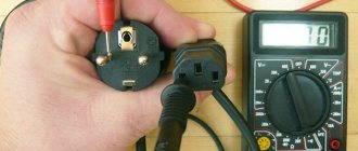
All multimeters have a similar design. There is a screen on the front panel, under it there is a rotary mode switch, and just below there are connectors for connecting probes. Some models have buttons to turn on the backlight, remember readings, and for other additional functions.
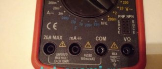
Wires with probes that need to touch the part when measuring are connected to the corresponding connectors. The black wire is always to the socket marked COM, and the red wire, depending on the current value. If it does not exceed 200 mA, then to the VΩmA connector, if it exceeds, then to 10ADC (10A MAX). Such high currents are not encountered in everyday life, so the VΩmA socket is mainly used.
The numbers on the scale indicate the maximum value that can be tested within that range. For example, in DCV 20 mode, DC voltage is measured from 0 to 20 V. If it is 21 V, then you need to switch one step higher, to position 200. It is important to select the range in accordance with what is being measured, otherwise the multimeter will be damaged.
Expert opinion
It-Technology, Electrical power and electronics specialist
Ask questions to the “Specialist for modernization of energy generation systems”
How to measure voltage, current, resistance with a multimeter, check diodes and transistors » Website for electricians - articles, tips, examples, diagrams So don’t be surprised if the multimeter doesn’t want to measure current at these limits, but immediately remove the back cover and look at the fuse. Ask, I'm in touch!
How to measure DC voltage with a multimeter
Switch to constant voltage mode. It is usually denoted by the symbols V with a straight line and a dotted line, or DCV.
In multimeters with manual range selection, additionally set the approximate measurement value, or preferably one step higher. If you are not sure, start with the maximum and gradually lower.
Touch the probes to the contacts and look at the screen. If a minus sign is displayed along with the number, it means that the polarity is reversed: the red probe touches the minus, and the black probe touches the plus.
In a hand-held multimeter, you may have to adjust the measuring range.
If the display shows a unit, you need to increase the measurement limit; if it is zero, the OL or OVER symbols need to be lowered.
What kind of lighting do you prefer?
Built-in Chandelier
Repair of multimeter DT-838
Repair of multimeter S-Line DT-838
I checked the transistors with a tester and they turned out to be all faulty, I almost threw them out. But it turned out that the multimeter was faulty. (ha ha)
And so the multimeter was buggy when measuring resistance and when making a call, but it beeped. The voltage showed normal.
When I searched for a diagram I couldn’t find exactly this one, I came across this one:
Having disassembled the board, I noticed that R3 (the marking on the board is different on the diagram) there is a small point (152 is written on the resistor) 1.5 kOhm, measuring it with another multimeter (I have a generally glitchy one, but you can navigate it) showed more than 2 kOhm.
After the replacement everything worked. I took the resistor from the old computer motherboard, desoldered it and soldered it with a hairdryer on a homemade soldering station.
Share link:
Similar
on “Repair of multimeter DT-838”
please tell me the value of the resistor R16 is very necessary or the diagram if you have it, thanks in advance!
On my resistor R16 it says 561, which is 560 Ohms.
This photo is really hard to see
Same thing ((Where is this cut on the mother? I didn’t see it((tell me, or what to replace it with (where to remove it from)?
Found it... soldered it in... didn’t work ((or rather, it’s still buggy.
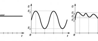
Repairing the dead is good. What about eliminating the factory (Chinese) defect? Now they sell DT-838 (allegedly) from different brands (Ermak, Resanta, TEK), but with the same defect, which appears ONLY when measuring temperature. Temperatures above 100-150 C are overestimated, and the higher they are, the more they are overestimated (see graph).
By heating the thermocouple from the multimeter kit in the flame of a lighter, it is easy to get 1999 C and even overload. In reality, it is quite difficult to get even 1000 C on a lighter, and at 1500 C the thermocouple conductors should have already melted.
The point, of course, is not in the thermocouple, but in the multimeters themselves: during the next Chinese “optimization” an error crept in, which has since been successfully replicated. Reviews mentioning a defect by Russian sellers are simply not published (I didn’t check all of them - one was enough)
I just found the error (in the board layout) (after a lot of sweat). It's easy to fix. The temperature becomes correct, and the correction does not affect other modes in any way. I'll probably post this somewhere more appropriate.
Repairing the dead is good. What about eliminating the factory (Chinese) defect? Now they sell DT-838 (allegedly) from different brands (Ermak, Resanta, TEK), but with the same defect, which appears ONLY when measuring temperature. Temperatures above 100-150 C are overestimated, and the higher they are, the more they are overestimated (see graph).
By heating the thermocouple from the multimeter kit in the flame of a lighter, it is easy to get 1999 C and even overload. In reality, it is quite difficult to get even 1000 C on a lighter, and at 1500 C the thermocouple conductors should have already melted.
The point, of course, is not in the thermocouple, but in the multimeters themselves: during the next Chinese “optimization” an error crept in, which has since been successfully replicated. Reviews mentioning a defect by Russian sellers are simply not published (I didn’t check all of them - one was enough)
I just found the error (in the board layout) (after a fair amount of sweat) and fixed it. It's easy to fix. The temperature becomes correct, and the correction does not affect other modes in any way. I'll probably post this somewhere more appropriate.
Features of measuring currents with a multimeter
To measure “high” currents, you will have to switch the red probe into the socket labeled 10A. A warning notice can be seen near this socket stating that this limit is not protected by a fuse and measurements can only be taken for 10 seconds, after which a break of 15 minutes can be taken.
Those who have used pointer testers know that before starting to measure resistance, you need to set the pointer to scale zero. To do this, simply connect the measuring probes and turn the corresponding knob.
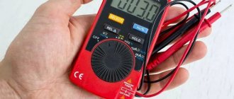
Although digital multimeters do not need to be set to zero, you still have to connect the probes: this is another good rule for using the device. Thus, first of all, the integrity of the probes is checked (standard probes break very often), and at the same time the scale zero. If the multimeter is in the “dial” mode (as shown in the figure), a beep will sound.
A sound signal is heard only if the resistance between the measuring probes does not exceed 47...50Ω. This property is used when checking the integrity of conductors and tracks on printed circuit boards. The mode for testing semiconductors is also combined with the wire testing mode.
If the input probes are not shorted, or there is an open circuit in the circuit under test, or the diode being tested is switched on in reverse polarity, 1 is displayed on the multimeter display:
The same thing can be seen on the display if you try to measure a resistance of 200KOhm at the limit of 200Ohm. In other words, the measured resistance is higher than the measurement limit, the device “thinks” that the circuit is open.
The same picture will happen if the 24V voltage is measured in the range of 20 - the device is off scale. Just don’t apply a voltage of 100...200 volts to range 20, since the device may not withstand such abuse and will simply burn out.
Expert opinion
It-Technology, Electrical power and electronics specialist
Ask questions to the “Specialist for modernization of energy generation systems”
How to use a multimeter correctly - Lifehacker The wires in the measuring probes are attached only by soldering, and when they come out of the plastic tips they dangle and dangle freely, and over time they unwind completely and fly out. Ask, I'm in touch!
Why is the mode called “dialing”?
It was possible to check the integrity of the circuit before using the resistance measurement mode - an ohmmeter. The main difference between dialing is that during measurements, if there is an electrical connection between the tested areas, then, in addition to the readings on the screen, a sound signal is heard - a buzzer, which is where the term dialing or ringing came from.
This sound signal significantly speeds up the verification process, you don’t have to be distracted, look at the screen, and it’s not always convenient, and when you hear the buzzer (or not), you already know the result. This is especially useful for mass measurements, for example, when searching for one specific wire in a bundle.
We measure alternating voltage.
The process of measuring alternating voltage is similar to measuring direct voltage with the only difference that there is no need to determine where “ plus”
" and "
minus
". As an example, let’s measure the voltage of a household electrical network of 220 Volts.
Attention! Be especially careful and extremely careful when measuring high voltages. Do not touch the metal parts of the probes.
This sector is divided into only two subranges with measurement limits:
indicating the maximum value of the subrange within which the measurement is carried out. The measuring leads are the same as when measuring DC voltage.
Selecting the measurement limit 750
Volt.
Additionally, we make sure that the insulation of the wires and probes of the multimeter is in good condition. Once again we check the correctness of the selected measurement limit, and only after that we measure the 220 Volt network voltage
.
As you can see, everything is very simple. And here we also do not forget that when measuring an alternating voltage, the value of which is unknown, to determine it, we start only from the maximum limit
, namely with
750
Volts.
After finishing work with the multimeter, be sure to turn it off by moving the switch to the “ OFF”
“, otherwise you won’t have enough batteries.
To finally understand how to measure voltage with a multimeter, watch this video.
How to measure current
,
resistance
, how to use
a continuity tester
and
a sound generator
, read in the second part of the article how to use a multimeter for beginners. Good luck!
Expert opinion
It-Technology, Electrical power and electronics specialist
Ask questions to the “Specialist for modernization of energy generation systems”
How to measure DC voltage with a multimeter A multifunctional device combines a voltmeter, ammeter, ohmmeter, continuity test, and may also have additional functions such as a thermocouple or low-frequency generator, testing capacitors and transistors. Ask, I'm in touch!
Features of checking wires included in various devices
First, let's look at the features of work in conditions where the on-board wiring of a modern car is checked using a multimeter.
Automotive wiring
The specificity of this situation is that the wiring in the case under consideration consists of one linear conductor with a supply voltage of 12 Volts. In this case, the metal body of the car is used as the second (common or “ground”) conductor, where, as a rule, there is nothing to break.
To prepare the on-board network for inspection, you first need to disconnect the positive terminal from the battery, after which you can safely begin work. Testing of on-board wiring is organized according to the previously described linear circuit testing scheme.
Important! When checking the “ground” of a car, the main attention is paid to the quality of contact of the supply terminals with the body .
Electric heating element
Based on the indicator readings on the multimeter, it is possible to make a continuity test on an element such as a water heating element. During the test, the control probes of the device touch the two contact plates of the heater and evaluate its internal resistance using the indicator.
If the display shows about a few ohms, then without a doubt the element is working. With large values on the screen corresponding to a break in the line being tested, you can immediately say that the heating element is damaged and must be replaced.
In addition to the heating element itself, when checking boilers and similar devices, it is very important to ring the supply cable for unwanted contact with the device body. For this purpose, one of the multimeter probes is connected in turn to the input contacts; in this case, the second end is constantly held on the heater body.
If the digital multimeter shows some resistance during measurement, this means that the protective sheath of the supply cable is damaged. To prevent electric shock to the user, it should be replaced with a new one.
Other household appliances and parts
Using a multimeter, you can test the power circuit of any lighting device by testing the wiring and auxiliary elements (switches, in particular) for a short circuit or open circuit. To do this, first of all, you should ring two linear chains ending directly at the contacts of the light bulb.
Additional Information! Before testing the lighting device, first of all, make sure that the light bulb itself is working properly by replacing it in a known-good device.
When testing linear chains, be sure to check the serviceability of the switch located in one of them, as well as the reliability of connecting the conductors to its contacts.
We also note that using this method it will be possible to ring the windings of a linear transformer or electric motor and verify their integrity or the presence of a break (short circuit).
In conclusion, let us remind you once again that using a multimeter you can check not only individual wires or wiring hidden in the thickness of walls, but also any other electrical devices and parts.
The main functions of the M-831 digital multimeter and the purpose of the device controls
Let's take a closer look at the external panel of the multimeter. Here we see in the upper part a seven-segment liquid crystal indicator, on which the values we measure will be displayed.
Further, one might say, in the center of the device, there is a switch for quantities and measurement limits.
Let's take a closer look at all the symbols that are printed in a circle, thereby analyzing the operating modes of the multimeter.
1 - turn off the multimeter.
2 - mode for measuring alternating voltage values, has two measurement ranges of 200 and 600 volts.
In other models of multimeters, the designation ACV may be used - AC Voltage - (eng. Alternating Current Voltage ) - alternating voltage
3 - mode for measuring direct current values in the following ranges: 200 µA, 2000 µA, 20 mA, 200 mA.
DCA may be used - (eng. Direct Current Amperage ) - direct current.
4 - mode for measuring large values of direct current up to 10 amperes.
5 - audio testing of wires, the sound signal is turned on when the resistance of the section being tested is less than 50 Ohms.
6 - checking the health of the diodes, shows the voltage drop at the pn junction of the diode.
7 - mode for measuring resistance values, has five ranges: 200 Ohm, 2000 Ohm, 20 kOhm, 200 kOhm, 2000 kOhm.
8 - mode for measuring DC voltage values, has five ranges: 200 mV, 2000 mV, 20 V, 200 V and 600 V.
DCV - DC Voltage - (eng. Direct Current Voltage ) - constant voltage may be used
In the lower right corner of the front panel of the multimeter there are three sockets for connecting the included cords with probes.
Everything is simple here:
— lower socket for the common (negative) wire in all modes and on all ranges;
— middle socket for the positive wire in all modes and on all ranges except for the current measurement mode up to 10 A;
— upper socket for the positive wire in current measurement mode up to 10 A.
Be careful, when measuring current more than 200 mA, connect the positive wire only to the upper socket!
The multimeter is powered by a 9-volt Krona battery or, according to the standard size, 6F22.
Inside, under the back cover of the multimeter there is a fuse, usually 250 mA, which protects the device in current measurement mode up to 200 mA.