In modern life, there are often situations when it is necessary to ring a certain circuit or electrical device with a tester. Most often they occur when a socket or key switch stops working, as well as when contact is lost or there is a break in the power circuits of individual devices. If the owner is used to doing everything on his own, he needs to acquire a very practical and easy-to-use device called a multimeter.
With its help, you can check the serviceability of any electrical device, including a regular light bulb, a section of wiring or a conductor included in it. But in order to correctly test a circuit with a multimeter, you should first become familiar with the basic techniques for working with it.
In the following sections of the article, each of the possible options for using a multimeter will be discussed in more detail.
Continuity check (searching for the right conductor)
To check the integrity of electrical wiring or search for one core in a multi-core cable, a digital tester turned on in resistance measurement mode is sufficient. When carrying out such an operation, it is necessary to create a closed chain consisting directly of a multimeter (tester), a pair of measuring “ends” and the conductor being tested itself.
In this case, a small electric current is passed through the test area, and the multimeter determines the value of its internal resistance. This is not a dialing test yet, but it is a fairly convenient method.
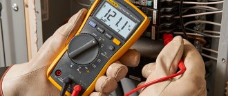
During such a test, according to the readings of the multimeter display, it will be possible to judge the integrity or break in the section of the circuit or conductor being tested. A reading of zero or close to several ohms means that the wiring is not broken; at the same time, the electric current generated by the device flows freely through it.
It is also possible that during testing it is discovered that the device displays readings in the megohm region, but does not produce a sound signal during the test call. This means that there is an internal break in the wiring section that is not visually detectable.
Essentially, a vertebra is a determination with a multimeter whether there is contact between the wires or not. The multimeter produces a small current, and if the circuit is intact, then the voltage is recorded, as a result, a sound signal is heard - a bell, and zeros are displayed on the multimeter display. The continuity test checks fuses, light bulbs, wires, and the integrity of circuits.
In a similar way, using a multimeter, a short circuit of conductors is detected, which in working condition should not have contact with each other. In a working cable, each individual core should show a small resistance (from fractions to several ohms) when tested.
The resistance value is determined by the total length of the cable product being tested with a multimeter. At the same time, there should be no contact between all components of the multi-core cable and adjacent conductors, which checks continuity.
Cable testers
This class of devices allows you to check both the integrity of the cable and the correctness of its connection, which is very important for Internet provider networks. These can be simple devices that check crossover or complex devices on a PIC controller that have an ADC and a built-in multiplexer.
Multipurpose cable tester Pro'sKit MT-7051N on a microcontroller
Naturally, the cost of such devices does not encourage their household use.
Wiring check
Testing conductors using a multimeter is functionally provided in most digital devices of this class. To set the dialing mode, just set the switch to the position marked with the “Buzzer” icon and prepare the measuring chain shown in the figure.
If current flows through the piece of wire being tested, the multimeter will produce an audible signal (buzzer). Naturally, to test a section of a circuit several meters long, you will need an additional wire used to expand the measuring circuit.
Another option for testing phase and neutral linear conductors of considerable length involves twisting them at the remote end of the electrical wiring.
In this case, to check the circuit for an open circuit, it is enough to connect the multimeter's test leads to the free contacts of those ends of the electrical line that are located closer to the device.
The last of the proposed options has the following advantages:
- using this method, you can use a multimeter to immediately test both wires of electrical wiring connected in a series chain;
- checking the wire in this way is much easier than the first way, since you can do without an additional segment that allows for extension of the measuring circuit.
Before checking the electrical wiring hidden in the thickness of the walls, you should first carefully read the wiring diagram. In addition, it is necessary to remove the operating voltage from it by turning off the circuit breaker corresponding to this line.
What to look for when purchasing
In electrical goods stores you will find a lot of different models of detectors, differing in both functionality and price. The simplest of them do not give an idea of the location of the break as accurately as more expensive devices, but this is enough for successful troubleshooting and troubleshooting with your own hands.
Well, the best and most advanced detector models can easily distinguish energized wiring from de-energized wiring, and can also indicate the presence of certain materials in the wall. It all depends on the technologies used in a particular device.
Using improvised means
Testing wires with a multimeter is not the only possible option for testing them for continuity or breakage. You can verify the serviceability of any linear conductor without the help of this universal device.
To carry out such a check you will need:
- a regular battery (preferably a 4.5-volt square one);
- a 3.5 Volt light bulb, with which the linear section of the wire being tested is checked (monitored);
- a pair of connecting wires and a gripping type connector (the so-called “crocodile”).
After preparing all the necessary elements, a simple measuring chain is assembled on their basis, consisting of a test light, a battery and the conductor being tested. If the circuit is correctly assembled and if the tested area is in good condition, the control light will light up. The absence of a glow even though all circuit elements are working properly indicates a break in the conductor itself.
When testing in this way, the same principle is used as when checking with a multimeter turned on in the dialing mode.
Signs of faulty electrical wiring in the apartment
Let's figure out how to find a fault in the electrical wiring? Malfunctions arise due to incorrect or careless installation, violation of the integrity of the insulation, broken wires, poor contact between circuit elements or network overload. A malfunction is indicated by:
- Lack of zero; Lack of phase; Lack of phase and zero at the same time; Sparking; Short circuit.
Indirectly, a malfunction is indicated by too frequent operation of the protective automation.
Features of checking wires included in various devices
First, let's look at the features of work in conditions where the on-board wiring of a modern car is checked using a multimeter.
Automotive wiring
The specificity of this situation is that the wiring in the case under consideration consists of one linear conductor with a supply voltage of 12 Volts. In this case, the metal body of the car is used as the second (common or “ground”) conductor, where, as a rule, there is nothing to break.
To prepare the on-board network for inspection, you first need to disconnect the positive terminal from the battery, after which you can safely begin work. Testing of on-board wiring is organized according to the previously described linear circuit testing scheme.
When checking the “ground” of a car, the main attention is paid to the quality of contact of the supply terminals with the body.
Electric heating element
Based on the indicator readings on the multimeter, it is possible to make a continuity test on an element such as a water heating element. During the test, the control probes of the device touch the two contact plates of the heater and evaluate its internal resistance using the indicator.
If the display shows about a few ohms, then without a doubt the element is working. With large values on the screen corresponding to a break in the line being tested, you can immediately say that the heating element is damaged and must be replaced.
In addition to the heating element itself, when checking boilers and similar devices, it is very important to ring the supply cable for unwanted contact with the device body. For this purpose, one of the multimeter probes is connected in turn to the input contacts; in this case, the second end is constantly held on the heater body.
If the digital multimeter shows some resistance during measurement, this means that the protective sheath of the supply cable is damaged. To prevent electric shock to the user, it should be replaced with a new one.
Other household appliances and parts
Using a multimeter, you can test the power circuit of any lighting device by testing the wiring and auxiliary elements (switches, in particular) for a short circuit or open circuit. To do this, first of all, you should ring two linear chains ending directly at the contacts of the light bulb.
Additional Information! Before testing the lighting device, first of all, make sure that the light bulb itself is working properly by replacing it in a known-good device.
When testing linear chains, be sure to check the serviceability of the switch located in one of them, as well as the reliability of connecting the conductors to its contacts.
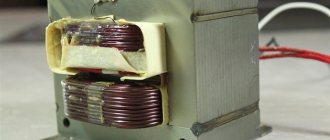
We also note that using this method it will be possible to ring the windings of a linear transformer or electric motor and verify their integrity or the presence of a break (short circuit).
In conclusion, let us remind you once again that using a multimeter you can check not only individual wires or wiring hidden in the thickness of walls, but also any other electrical devices and parts.
Optional equipment
During operation, car owners often install additional electrical equipment:
- Alarm;
- More powerful lighting fixtures;
- Audio and video equipment, etc.
Integrating them adds wiring to the vehicle and also puts stress on the electrical system. Moreover, a number of “new” electricity consumers cannot be switched off, for example, alarm systems, which means that the likelihood of rapid battery discharge becomes very important.
If your car begins to have difficulty starting after a long period of parking, then you should determine the cause of the current leak. A multifunctional device switched to ammeter mode will also help you find a leak.
Tip: Don’t forget to set the measurement range to 10 Amps, since the current in the car’s on-board network is constant.
Elimination of broken phase and neutral wires
Having found out the exact location of the cable break and determined its peculiarity (damage to the “phase”, “zero”), you can begin to repair it.
To eliminate a damaged phase wire, follow these steps:
- First of all, you need to disconnect the phase wire.
- Using a hammer or other tool, remove plaster or other finishing from the wall surface. It is necessary to clear the area along the route by approximately 10-15 cm, covering the area to the right and left of the expected center of damage.
- It is necessary to separate the damaged core from the network, being careful not to touch the insulation on other cables.
- It is better to connect copper wiring by soldering. To do this, you need to take an additional piece of a similar product from which the repair jumper is made.
- It is also advisable to first place a polyvinyl chloride or heat-shrink tube on the core of the damaged cable. The ends of the jumper are twisted with the ends of the broken wire, after which the connections are soldered.
- Insulating tape is applied tightly (in several layers) to the repaired area, after which the tube covered with the wire is carefully pushed onto it. This ensures the tightness of the fastener.
Aluminum wires are less amenable to soldering, which also requires special solder and flux. In this case, the most reliable connection method will be the WAGO terminal, and the place of its attachment must be wrapped with electrical tape and additionally covered with sealant.
The wires can also be connected using a junction box. To do this, the insulation is removed from the broken wire, after which its ends are separated in different directions. Using a hammer drill equipped with a special crown, a hole is punched in the wall, the dimensions of which coincide with the parameters of the branch box.
The device is inserted into the opening, after which it is secured with alabaster. The wires are placed in the box, while the damaged wires are connected by color and wrapped with insulating tape. Finally, the box with the restored wires is closed with a lid.
If the cables are placed in special tubes, the damaged wires should be carefully pulled out, and new wires should be inserted in their place using a pulling device.
If the neutral cable is damaged at the beginning of work, it must be disconnected from the bus by attaching the phase conductor. The rest of the process coincides with the regulations described above.
After any type of repair, the grooves are covered with plaster. It is possible to apply voltage to the repaired wiring only after the coating has completely dried.
Video
From all of the above, we can conclude that having a multimeter with a dialing function in the house is an objective necessity for any home craftsman. With such a device, in most cases it will be possible to quickly eliminate minor faults without turning to specialists for help.
Due to a violation of the integrity of the wiring, walled up under a layer of finishing materials, apartment residents may be left without the usual amenities. To restore the current supply, you need to know how to find a broken wire in the wall and correct the situation.
We will tell you how and with what tools damage to electrical wiring is detected. We will show you how to eliminate the detected faults. You will learn what needs to be done to prevent such problems.