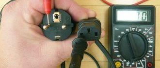
If you need to find a malfunction of equipment or electrical wiring, one of the operations that is performed first is to test the cables and wires with a multimeter (tester) to check the serviceability of the circuit (no breaks in it), the presence of a short circuit and determine its resistance (if necessary ). In this way, it is possible to easily and quickly check the serviceability of a lamp, iron, switch, fuse, transformer. This article will discuss how to test wires correctly with a multimeter.
What is used for wiring
Professional and homemade testers are used to check for broken wires or to detect a short circuit. Self-produced devices are presented in the form of a battery and a light bulb attached to it.
Professional testers are multimeters, with which you can not only test wires, but also perform a number of other diagnostic work on the electrical network.
This is a convenient and easy-to-use device that is always in the electrician’s arsenal.
Finding the location of a short circuit or broken wire
So, we already know how to test wires with a multimeter. All that remains is to learn how to determine whether a wire is broken or a short circuit in the wall. At the moment, there are special devices for determining the location of cliffs. But their price is quite high and, if you do not plan to earn money from this, such a purchase is not advisable.
- As we have already said, there are now many methods and devices for determining the location of a wire break. I will give an example of just one, which I have been using for many years and which has never let me down.
Capacitive voltage indicator "FLUKE"
- It only requires a capacitive voltage indicator. I use it, but this issue is not important. The main thing is that it works correctly, and not from the slightest movement. There are those too. Its cost is not so high, and it is quite a necessary thing in the household.
- To determine the location of a phase wire break, you simply move it from the distribution box, where there is voltage, along the wall along the intended location of the wire. As long as there is voltage on the wire, the indicator lights up. At the site of the break it will go out.
- To determine the location of the break in the neutral wire, you just need to briefly make it phase. To do this, first of all, we relieve tension. Then we disconnect the phase neutral and protective wires and connect the neutral wire to the supply phase wire. After applying voltage, we proceed in the same way as when searching for a broken phase wire. Don't forget to restore the schema after searching.
- If there is a short circuit with a break, then disconnect all wires except the phase wire, and then apply voltage. Then we proceed in the same way as when searching for the location of a broken phase wire.
How dialing works
The multimeter has its own power source, and with its help voltage is supplied to the de-energized conductor.
Voltage is applied to the conductor through a multimeter.
Every material has a resistance that can be measured or calculated. A multimeter set to the “resistance determination” position is used to test the wire. The display of the device indicates the resistance value of the material.
The current strength I is directly proportional to the voltage U and inversely proportional to the resistance R. Many people remember this formula from physics lessons.
I=U/R
This means that the voltage that is in the multimeter is supplied to the conductor being tested. The material data is analyzed and the result is displayed.
The very fact that it was possible to find this value explains that the conductor is not damaged.
Multimeter for testing wires
What do you need to know about this device? Firstly, it is worth noting the price variety and availability. Even inexpensive multimeters can flawlessly cope with many tasks, including testing wires.
Let's take a closer look at a typical budget option. Let's get acquainted with the design, layout and determine its functionality.
As you can see, a typical device has a digital display, controls and sockets for connecting probes. Let's decipher the main modes of the multimeter:
- OFF – the device is turned off (some devices have a special button for this).
- ACV (may be designated V~) – measurement of alternating voltage.
- DCV (can be designated V...) – DC voltage measurement.
- ACA (may be designated A~) – measurement of alternating current.
- DCA (may be designated A...) – direct current measurement.
- Ω - resistance measurement.
- hFE – measurement of transistor parameters.
- ->Ι- – conductivity check (circuit continuity).
The sockets for connecting probes are marked as follows:
- COM(-) – common socket for connecting the black wire.
- VΩmA(+) – socket for connecting the red wire.
- 10A...MAX – socket for connecting the red wire when measuring direct current, the maximum value of which does not exceed 10 Amperes.
Within the framework of the issue under consideration, only two modes of the multimeter will be considered:
| Resistance measurement mode. |
| Conductivity test (continuity) mode. |
| Availability of sound when checking conductivity. |
The presence of sound, which is not mandatory, complements the dialing mode and simplifies the verification process. You do not need to constantly be distracted and look at the device display. The presence or absence of a buzzer signal will give a clear indication of the integrity of the conductor being measured.
In what cases is an inspection carried out?
Testing is used when it is necessary to ensure the integrity of the circuit.
There are different cases:
- broken switch or socket;
- failure of household electrical appliances;
- checking printed circuit boards;
- car wiring diagnostics;
- searching for the required core among a large number of other conductors;
- diagnostics of communication lines, as well as lighting and power networks during their installation.
They resort to checking the wires when the socket breaks down.
Checking the wires with a faulty switch or socket should be carried out only after other possible failures have been ruled out.
For example, a broken connection or a defective electrical current receiver.
The causes of damage to wires can be mechanical impact (during repair work) and overloads that cause a short circuit. It can also be determined with a multimeter.
Features of checking wires included in various devices
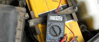
First, let's look at the features of work in conditions where the on-board wiring of a modern car is checked using a multimeter.
Automotive wiring
The specificity of this situation is that the wiring in the case under consideration consists of one linear conductor with a supply voltage of 12 Volts. In this case, the metal body of the car is used as the second (common or “ground”) conductor, where, as a rule, there is nothing to break.
To prepare the on-board network for inspection, you first need to disconnect the positive terminal from the battery, after which you can safely begin work. Testing of on-board wiring is organized according to the previously described linear circuit testing scheme.
When checking the “ground” of a car, the main attention is paid to the quality of contact of the supply terminals with the body.
Electric heating element
Based on the indicator readings on the multimeter, it is possible to make a continuity test on an element such as a water heating element. During the test, the control probes of the device touch the two contact plates of the heater and evaluate its internal resistance using the indicator.
If the display shows about a few ohms, then without a doubt the element is working. With large values on the screen corresponding to a break in the line being tested, you can immediately say that the heating element is damaged and must be replaced.
In addition to the heating element itself, when checking boilers and similar devices, it is very important to ring the supply cable for unwanted contact with the device body. For this purpose, one of the multimeter probes is connected in turn to the input contacts; in this case, the second end is constantly held on the heater body.
If the digital multimeter shows some resistance during measurement, this means that the protective sheath of the supply cable is damaged. To prevent electric shock to the user, it should be replaced with a new one.
Other household appliances and parts
Using a multimeter, you can test the power circuit of any lighting device by testing the wiring and auxiliary elements (switches, in particular) for a short circuit or open circuit. To do this, first of all, you should ring two linear chains ending directly at the contacts of the light bulb.
Additional Information! Before testing the lighting device, first of all, make sure that the light bulb itself is working properly by replacing it in a known-good device.
When testing linear chains, be sure to check the serviceability of the switch located in one of them, as well as the reliability of connecting the conductors to its contacts.
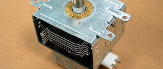
We also note that using this method it will be possible to ring the windings of a linear transformer or electric motor and verify their integrity or the presence of a break (short circuit).
In conclusion, let us remind you once again that using a multimeter you can check not only individual wires or wiring hidden in the thickness of walls, but also any other electrical devices and parts.
Setting up the multimeter
To diagnose the integrity of the wires on the multimeter, you need to set the continuity mode. The measuring device comes with two wires with probes: red and black. They need to be inserted into the corresponding sockets: “COM” - for black, “VωmA” - for red. In this way, polarity is observed when measuring.
To check the serviceability of the tester, the probes of the red and black wires must be connected to each other. A characteristic bell is heard - the multimeter is ready for use.
Indicators and their interpretation
When checking conductors, digital values appear on the tester’s display, which determine the presence of resistance in the conductor.
While checking the conductors, digital values appear.
A signal sounds and the number “0” (or close to zero) is displayed on the screen - the conductor is not damaged.
If there is no sound and the device shows “1”, there is a break in the wire.
Limits of values
If you check the integrity of the conductors in the “resistance determination” mode, then it is necessary to set the limits of the values.
Values entered manually are always multiples of 2. For testing long wires - 20 ohms. The minimum figure that can be specified is 2 ohms.
Connecting the tester
The multimeter, set in the desired mode, is connected with two probes to the contacts of the conductor being tested. For convenience, the probes and ends of the wire are sometimes secured with metal clips - “crocodiles”. The tester immediately displays diagnostic results on the screen.
We check the wiring in the apartment with a multimeter
Let's take as an example a modern apartment in which the wiring is done in accordance with current requirements and standards. This means that when laying the lighting lines and power outlets, they were separated, and separate wires were laid for them in each of the rooms. Each of these circuits is powered from the apartment panel through a separate circuit breaker.
If the light has gone out in one of the rooms, you should first check that the lamp is working properly. Before starting work, it is necessary to turn off the power to the room/apartment depending on the power supply. When using an opaque incandescent lamp in a lamp, the integrity of the filament is difficult to visually determine, so you will need a multimeter and its continuity function. Let's figure out step by step how to do this correctly.
First you need to check the shield for triggered circuit breakers. In the first case, they will be in the on position (then the fault may be hidden in the room switch, lamp or socket). The likelihood of damage to the wiring in such a situation is low. If the device works, you will need to check everything except the room switch, including the switchboard itself.
If the machines don't work
We ring the switch. When the switch is on, there should be a sound signal, when off, there should be silence and “1” on the indicator.
- Make sure there is voltage at the input and output of the machine. If it is, you can proceed to further verification.
- Prepare the device for operation and check its serviceability by short-circuiting the measuring leads.
- Unscrew the lamp from the socket.
- Touch one of the measuring probes to the base (the metal part of the lamp with threads), and the second to the central contact of the lamp (the insulated center of the end part of the base).
- A sound signal and instrument readings that are different from 0 or 1 mean that the lamp is working. If it is faulty, you need to replace it, which will solve the problem.
- We check the cartridge for serviceability. To do this, you need to disassemble the lamp, make sure that the connected wires and contacts are intact. If everything is in order, then the cause of the failure is not in the cartridge. If malfunctions are detected, they must be eliminated. The lamp cannot be screwed in yet.
- We check the serviceability of the room switch. To do this, remove the plastic cover, unscrew the screws and take it out of the mounting box. We inspect the equipment for the appearance of carbon deposits and check the tightness of the fasteners. If everything is in order, you need to install the measuring ends of the tester on the contacts of the switch. The appearance of a sound signal when dialing in the on position will indicate that the equipment is working properly. The wires do not need to be disconnected.
During such a check, as a rule, a malfunction is identified, which becomes the cause of all the troubles. Eliminating it allows you to quickly solve the problem.
If the machine worked
To ensure electrical safety during work, in this case the voltage is turned off using a general apartment circuit breaker. Next, the serviceability of the socket and the wires connected to the lamp is determined according to the algorithm described above. If there are no faults, you need to check the wiring itself using a multimeter and the continuity function. Such malfunctions happen quite rarely, but they still happen, for example, when installing suspended ceilings or decorative interior elements.
The wiring in this case is performed as follows.
- Using a screwdriver, disconnect the connected conductor (if installed correctly, it is located at the bottom) and move it to the side. The “zero” of this group is, as a rule, located at the zero clamp under the machines.
- Unscrew the incandescent lamp from the socket. Using a ready-to-use tester, we check the line by connecting one of the measuring probes to “zero” and the other to the disconnected conductor. If the device beeps, it means the wiring is shorted.
- In this case, in the room under the ceiling above the switch, we find and open the junction box. We disconnect the wires.
- We check all groups of wires for short circuits. To determine the section of the circuit in which there is a short circuit, we again check the circuits on the apartment panel with a multimeter. If the signal sounds, it means that it is the wire laid from the switchboard to the box in the room that needs to be repaired. Otherwise, the search will need to be continued until a result is obtained.
Checking the heating element
Before checking the device, you need to calculate its resistance. This is easy to do if you know the power of the heating element. It is indicated in his documents or on the back of the case.
You can calculate the resistance using the formula:
R=U²/P,
where U is the network voltage, P is the power of the heating element, and R is the resistance.
If the heating element has a power of 2000 W, and the mains voltage is 220 V, then the resistance calculated using this formula is 24.2 Ohms.
Before checking the heating element, its resistance is calculated.
Next you can proceed to the measurement process:
- Before checking the heating element circuit, you need to turn it off from the network and disconnect the wires.
- On the multimeter, set the “resistance measurement” mode and indicate the range up to 200 Ohms.
- Using the probes of the tester, touch the terminals of the heating element. If the device being tested is working properly, the multimeter display displays a number close to what was found using the formula. If the multimeter shows “1”, then there is a break. If “0” there is a short circuit inside the heating element.
In the continuity mode, the heating element can be checked for the presence of a breakdown on the body. To do this, connect one of the tester probes to the terminal of the device, and the second to its body or to ground. If there is a breakdown, the tester will beep.
How to check wire continuity in resistance detection mode
In multimeters that do not have a continuity function, checking the integrity of the wire can be done in the resistance measurement mode.
Determining resistance with a multimeter
In this case, the probes are connected in the same way as during dialing, and the device is set to resistance determination mode ( Ω ).
You need to start measuring at the very minimum threshold of the instrument scale - for example, 200 Ohms. All actions are the same as when calling. You just need to monitor the readings of the device. If the wire is intact, the display will show its resistance value. If there is a break, then the resistance will not be displayed (OL - overload condition).
Safety when using a multimeter
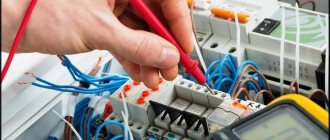
When working with the tester, you must remember the precautions and follow the safety rules:
- Before testing the circuit with a multimeter, turn off the power to the network.
- Place a warning sign near the switch that is turned off indicating that work is being carried out.
- Do not touch exposed wires with your hands.
- Work in specialized clothing and rubber gloves.
- If there are capacitors in the circuit, they must be discharged. Otherwise, the multimeter will be damaged. During the test, experts recommend:
- use “crocodiles” (these are clips that are attached to the ends of the tester wires; the contact becomes more reliable and your hands are freed);
- Do not touch bare wires or probes with your hands, otherwise the measurements will not be correct.
When using a multimeter, you need to turn off the power.
But if you have doubts about your diagnostic abilities, it is better to trust the specialists.
Testing multi-core cables for the purpose of marking them
When marking multi-core cables, you can use the methods described above, but there are ways to significantly simplify this process.
Method 1 : use of special transformers that have several secondary winding taps. The connection diagram for such a device is shown in the figure.
Using a transformer for marking
As can be seen from the figure, the primary winding of such a transformer is connected to the power supply network, one end of the secondary winding is connected to the protective shield of the cable, and the remaining terminals are connected to its conductors. To mark the wires, it is necessary to measure the voltage between the screen and each wire.
Method 2 : Use a block of resistors with different values connected to the cable wires on one side, as shown in the figure.
Resistors connected to cable terminals
To identify the cable, it is enough to measure the resistance between it and the screen. If you want to make such a device with your own hands, then you should select resistors in increments of at least 1 kOhm to reduce the influence of wire resistance. Also, do not forget that the value of the resistors has a certain error, so first measure them with an ohmmeter.
When checking a multi-core telephone cable, installers often use a dialing headset, for example TMG 1. Actually, these are two telephone handsets, one of which is connected to a 4.5 V battery. Such a simple device allows you not only to check the cable, but also to coordinate your actions during installation and testing.
Calling with a telephone handset
How to test wires with a multimeter
To check the wires, you must first turn off the power.
Then:
- bring the multimeter into working condition;
- set the desired mode;
- attach the probes;
- check the readiness of the tester.
After preparation, you can begin checking. Connect the multimeter probes to the bare ends of the wire. There is a signal - the conductor is intact.
Wiring in the apartment
In this case, each room has separate electrical wiring, which is powered through a circuit breaker from the panel.
If there is a power outage in your apartment, the first thing you need to check is the distribution board.
The electrical wiring in the house is powered through a circuit breaker.
If the machines do not turn off, the breakdown most likely lies in the receiver or in the room lamp switch. And if the protection has worked, you need to check all the wiring.
Dialing is allowed only in a de-energized network. Before diagnosing, it is necessary to check whether there is current in the circuit.
The first thing that fails is the outlet itself. You can identify defects in it visually by removing it from the socket. But it is better to perform diagnostics using instruments.
If it is in working order, the junction box is checked. It is located close to the outlet. The box contains twisted conductors: phase, ground and neutral. With one multimeter probe you need to alternately touch the contacts in the socket, and with the other, touch the bare ends of the twists. This is how a damaged conductor is identified.
Circuit continuity check
To test the continuity of the chain, it is necessary to check each element included in it. The multimeter probes must be connected to different ends of one wire, thus short-circuiting it. A sound was heard - everything is in order with the conductor, otherwise replacement is required.
Continuity of a long conductor
There are times when it is necessary to find out whether a wire whose ends are far apart is damaged. Then grounding is used for testing. You need to connect one end of the core being tested to the ground using a metal rod, and use the multimeter probes to touch the other end and the ground wire.
To test a long conductor, you can use grounding.
This results in a closed circuit in which the ground is the conductor.
How to ring a wire in a car
Testing the electronics in a car is carried out in the same way as in other cases: by touching the tester probes to the ends of the conductor. It is important to turn on the engine at idle speed before checking. In the case when only one contact is available for dialing, the second tester probe is placed on ground (the metal body of the car). It performs the function of grounding.
Fuse
This is a device that prevents elements in the circuit from overheating. It looks like a small plate or cylinder with a thin cable inside. To test it, multimeter probes are applied to different sides. In the “continuity” mode, if the fuse is intact, a sound should be heard.
In the “resistance determination” mode on the tester screen: “0” – no break, “1” – conductor damage.
Lamps
When checking, you need to connect one tester probe to the central contact, and the second to the side. Diagnostics also takes place in dialing mode.
Such a check can only be carried out with a screw base.
Diodes and LEDs
In a diode, polarity is determined by the anode and cathode. Therefore, it conducts current in one direction. To check an element, the appropriate mode is set on the tester. The poles of the diode are touched with the probes of a multimeter, and then they are swapped.
If, as a result of one test, the tester showed “0”, and during another “1”, the element is working.
The LED has reverse polarity. When the positive contact touches the anode and the negative contact touches the cathode, it lights up. When the position of the tester wires is changed, the voltage disappears. This determines that the LED is in working condition.
What you need to know about the device to connect wires
dialing mode
If you plan to test the wiring in your apartment, you need to know several fundamentally important facts about multimeters. First of all, it is worth noting that you can check the wire with the simplest device. An inexpensive Chinese model with minimal capabilities is quite suitable.
But at the same time, it is most convenient to use a device that has the dialing function itself. In order to set the device handle to the appropriate position, you need to turn it in the direction of the diode icon (as an option, an image of a sound wave can additionally be applied). This means that when checking the integrity of the wire, a sound signal will sound when the contacts are closed.
But the presence of sound is completely optional for testing wires with a multimeter. The fact that the circuit is broken will be indicated by a unit on the display, indicating that the resistance level between the probes is higher than the measurement limit. If there is no damage in the area under study, the resistance value will be displayed on the screen, which ideally should tend to zero (subject to operation in short-distance household networks).
Some features
Experts pay attention to points that must be taken into account when testing wires.
In adjacent rooms, sockets are installed in the same place opposite each other.
The sockets are installed opposite each other.
They do not always refer to the junction box that is nearby.
Sometimes the multimeter probes are not long enough to ring the wire connecting the junction box and the socket. To check the integrity of the conductors, the contacts in the socket itself are closed, and measurements are taken in the junction box.
In the absence of a tester
If you don’t have a multimeter at hand, you can ring the wire with a homemade device. It consists of a self-contained battery, a light bulb and two conductors. The ends of the battery leads, by analogy with a multimeter, are connected to the ends of the conductor being tested. The light bulb serves as a light indicator. If it lights up, the wire is not damaged.
If the machine does not work
If the light in the room goes out and the circuit breaker does not work, you need to perform a number of actions:
- Check if there is current at the output and input of the machine. If this is okay, move on to the next step.
- Unscrew the lamp and check it by touching one probe of the tester to the metal thread of the base, and the other to the main contact of the element. If the multimeter signal indicates that the device is working properly, the search for the problem continues.
- The cartridge is inspected visually; you can additionally call its contacts. If it is normal, check the switch.
- The outer housing of the room switch must be removed from the box and inspected. Check if there is charring on the wires or plastic, and if the fasteners are tight. Then the equipment is called.
If the circuit breaker does not work, you need to check the current at the input and output.
Often, the search for a defect in this context is limited to the above actions.
If the machine worked
In the event of a short circuit or network overload, circuit breakers cut off the power supply to the apartment or house.
After checking the light bulb, socket and switch, you need to check the wiring.
The algorithm of actions looks something like this:
- Set the multimeter to dialing mode.
- Connect one probe to the zero contact, the other to the working conductor. If the tester beeps, there is a short circuit in the circuit.
- In this situation, it is necessary to open the junction box to which the switch belongs and disconnect the wires.
- All contacts are called to find out which of them have shorted.
Thus, circuit diagnostics are carried out along the path from the receiver to the panel until the damage is identified and eliminated.
How to ring wires using a specific example
As an example, consider a standard wiring network in an apartment or private house. Ideally, all electrical communications should be made in accordance with the standards, all consumers are separated (grouped) and each circuit is powered in the distribution board through a specific machine.
Condition: the socket in one of the rooms stopped working. Task: identify the cause of the malfunction. Solution:
| The first step is to check the switchboard for automatic operation. If all the machines are in the on position, then it is necessary to de-energize the line under test (or the entire apartment). | |
| Now, to eliminate the banal version of a malfunction of the socket itself, it needs to be removed from the socket box and visually inspected for defects and poor contact. Conventional sockets have a simple design. For more expensive models that have terminal blocks as clamps, it is better to ring them additionally. | |
| After making sure that the outlet is working, you need to check the connection of the wires in the junction box. If there are several distribution boxes in the room, then the one you need will be located above the faulty outlet or in close proximity. | |
| In the distribution box, the main cable is broken, connected to the socket wires and then goes to the next consumer (distribution box). | |
| As can be seen from the example, there are three twists in the distribution box (phase, neutral, ground). When testing, the tip of one probe should touch the exposed twist. The second probe checks the socket contacts one by one. Or, if convenient, one probe is fixed in the socket contact, and the second one alternately checks the twists in the junction box. |
Having considered the main sequence of actions, we note important points and features during measurements:
- At the stage of checking the twists in the junction box, if there are no visible defects, you can additionally check the live connections. To do this, apply current by turning on the circuit breakers in the switchboard. If there are doubts about the color marking of the wires, the phase can be determined using an indicator screwdriver (when it comes into contact with a phase conductor, the indicator in the screwdriver lights up or a sound signal sounds). To find working and protective grounding, you will need a multimeter. After the phase conductor (L) is found, the ACV mode is set on the multimeter (can be indicated as V~ alternating voltage measurement) at a level above 220 V, the red phase probe is fixed on the phase conductor, and zero and ground are determined with the black probe. When in contact with the working ground (N), the device will display a voltage within 220 Volts. When the probe touches the protective ground (PE), the readings will be below 220 Volts. After checking, the apartment (room) should again be de-energized.
- Next point. It is not always possible to be absolutely sure that the wires from the outlet being studied go to the nearest junction box. It happens that sockets, bypassing distribution boxes, are powered with nearby sockets. A connection is also common, when two sockets in adjacent rooms are mounted at one point on a common wall. All this needs to be analyzed and taken into account.
- The issue of convenience of measurements is very relevant. After all, as a rule, the socket and the distribution box are located at a considerable distance, and the measuring probes of the multimeter often have a length of 30 - 50 cm. In this case, for convenience, you can insert a jumper into the socket (connect two contacts), and perform the test directly in the distribution box box. A more accurate measurement can be made by connecting the outlet to a working extension cord.
Example of cable testing
Before checking the cable, it is necessary to strip all its cores at both ends. After setting up the multimeter, you can begin testing.
The tester's probes are applied to adjacent wires at one end of the cable and ring them. If there is no short circuit, the tester should not indicate the presence of resistance and emit a sound signal. If it beeps, it means the wires are not connected to each other (shorted). This is how all conductors are checked in pairs.
Damage to the wires is excluded as follows:
- twist all the cable cores together at one end and the same at the other;
- place the multimeter probes on the twists;
- The entire cable is ringing.
If the test is accompanied by a sound signal, then everything is in order.
What does the dialing mode look like on a multimeter?
In the center of the digital tester, as a rule, there is a regulator that can be rotated in a circle and set to different positions. Each position corresponds to a specific option. Each option is indicated by a picture or text. The test icon can consist of one or a pair of symbols: a sound wave (required) and a diode (if the test mode is combined with the diode test mode).
What does the multimeter show when making a call?
The multimeter, when tested, shows the calculated voltage drop in millivolts in this circuit.
The current created by the tester in the area being tested, about 1 milliampere, was not chosen by chance, since the voltage drop in millivolts in this case corresponds to the resistance in Ohms.
In other words, when testing electrical circuits or electrical materials, we are shown the magnitude of the voltage drop, which is equal to the resistance of this section in Ohms.
A break is an endless resistance
A circuit (wire) continuity test is actually a resistance test. As you know, each wire has its own electrical resistance, but it is very small over a few (tens) meters. Thus, if there is the same wire on one and the other side of the multimeter probes, the resistance between its terminals should be no more than a few ohms. In home networks it is usually below 1 ohm.
When the resistance is tens of kΩ (kilo-ohms) or MΩ (mega-ohms), it means either there is a break in the circuit, or we are checking two different wires :)
Before checking anything, make sure that the cable or wire is not live. This is very important because otherwise this will be the last measurement taken with this multimeter. It is best to completely disconnect the cable from everything before checking, so that the work is more convenient and safer.
Possible results of checking the socket with a multimeter
There can be three of them:
- normal voltage;
- emergency;
- no tension.
Normal voltage
It can be 220 - 230V, although previously the voltage value of 220V was considered standard, and electrical appliances were manufactured and electrical networks were installed in accordance with it.
At a later time, 230V became standard. Therefore, in modern buildings the voltage is likely to be close to this value. Therefore, before measuring voltage, find out what standard your electrical network meets so as not to be alarmed when you see the results. Thus, measuring the voltage with a multimeter in a 220V socket does not at all mean getting exactly the same result.
Modern standards allow deviations from the nominal voltage value by ±10%. Therefore, relative to the 230V rating, taking into account deviations, values from 207 to 253V can be considered normal.
If you notice a constant voltage deviation even within these figures, this is a reason to contact the service organization with a request to check the causes of these deviations.
Emergency voltage
Any result outside the specified conditionally normal limits of 207 - 253V is considered an emergency. A lower number indicates network losses, a higher number indicates overvoltage.
The reasons for such deviations could be:
- errors in the design of the electrical network;
- problems with contacts.
Problems may also include the following:
- wear and tear of external electrical networks and equipment;
- incorrectly selected generating or distribution electrical equipment;
- overloads in the power grid.
These troubles are located outside the apartments and even the buildings themselves. In such a situation, other than measuring the voltage in the outlet with a multimeter, you cannot do anything yourself. You need to contact the organizations serving the house.
To weed out issues that can be resolved independently from those that are required to be resolved by special organizations, it is necessary:
- Open the electrical panel where the circuit breaker entering the apartment is located and measure the voltage on it. If it is standard, then it is worth checking the internal electrical network.
If you cannot diagnose yourself, contact a professional. Identifying the cause and eliminating it is a much cheaper option than the hypothetical probability of replacing all household appliances if they burn out.
- When the voltage on the cable entering the apartment does not correspond to the nominal value, contact the organization that provides power supply to the house, or notify the management company.
What will it show if the socket is faulty?
If there is no network, the multimeter will read 0 Volts. The reason is a faulty socket or lack of electricity. To determine the cause, you need to ring other outlets in the room. If only one does not work, its contacts are checked and, if necessary, replaced with a new one.
During voltage surges, the values on the multitester will differ greatly from the nominal 220 Volts. According to GOST, a deviation of 10% is permissible; a larger deviation can lead to damage to electrical appliances. If a strong voltage surge is detected, it is worth installing an additional stabilization device in the apartment. The home network operates at a voltage of 220 Volts, but in the outlet it may differ from the nominal value. Voltage within the limits established by GOST is the key to high-quality and stable operation of household appliances. It is important to be able to check voltage using a multitester to prevent the risk of damage to electrical devices. If there is a significant deviation from the set values, care should be taken to stabilize the voltage in the room.
How to measure 220 V with a multimeter
Multimeters are used for measurements. They come in two types:
- Pointer or analog. Such models were used before the advent of electronic ones. They are inexpensive, not demanding in operation and do not require a direct current source. The disadvantage of the device is the inconvenience of taking readings due to the size of the scale.
- Electronic or digital. These are modern, convenient devices with many functions. They cost more, but the reading accuracy is higher. Most specialists use this type of device.
- constant and alternating voltage;
- resistance;
- capacitive and frequency characteristics;
- direct and alternating current strength;
- parameters of diodes and transistors;
- temperature regime.
Switching modes is done using the knob on the device panel.
Work algorithm:
- Before starting work, the device is assembled. A black probe is always inserted into the connector labeled COM. The red one must be connected to the connector labeled VΩmA. There is a third 10 A output - this means that the multitester is capable of measuring current up to the specified value.
- After connection, the measurement mode is selected. It must be set carefully, since if the settings are incorrect, the device may fail. Changing the position of the switch during operation is prohibited. The rotary switch is set in the ACV or V field to position 750.
- Now the probes can be inserted into the sockets and see the result. A value of 220 V will have deviations; according to GOST, the error reaches 10%. If the value is outside the error range, it is recommended to install a voltage stabilizer at home.
Voltage measurement
It is very easy to check the voltage in an outlet with a multimeter. To do this you need to do the following:
- Switch the measuring device to voltmeter mode. Select the option of measuring alternating voltage using a circular knob with a measurement threshold of 600–1000 v. Each device has an individual threshold measurement parameter, as noted in the article above.
- Connect the red test lead to the first connector of the socket.
- Insert the black test lead into the second connector.
The AC voltage value will be displayed on the screen.
If the multimeter does not show a voltage value, this means that the electrical circuit has some kind of damage. Next, step-by-step instructions will be given on how to ring a socket with a multimeter.
Cable testers
This class of devices allows you to check both the integrity of the cable and the correctness of its connection, which is very important for Internet provider networks. These can be simple devices that check crossover or complex devices on a PIC controller that have an ADC and a built-in multiplexer.
Multipurpose cable tester Pro'sKit MT-7051N on a microcontroller
Naturally, the cost of such devices does not encourage their household use.
Multimeter
Before you check the voltage in an outlet, you need to know what a tester is and how to use it.
A multimeter or tester is a control and measuring device necessary for: measuring various parameters of electric current; testing of parts, wire and cable lines. To work with alternating current, the device is equipped with a function for measuring the value of this parameter. The device has a special designation - a wavy line ~ or the abbreviation ACV. Using modern multimeters, you can measure voltages from 200 to 1000 volts. The maximum voltage value depends on the device model and its degree of protection.
Multimeters are equipped with test probes, which are necessary for: connecting the measuring device to the contacts of the electrical installation; connecting the device to the general electrical circuit.