5 / 5 ( 1 voice )
The contactor is modular or, as it is often called, a magnetic starter or relay. When used correctly in electrical panel circuits, a modular contactor can be a very useful device, including indispensable when designing automatic transfer switches.
In my electrical panels, as a rule, I use a contactor to remotely (remotely) turn off/on consumers. For example, for controlling non-switchable lines in an apartment or private house, as well as for controlling heating systems together with the GSM controller “Xital” and other similar relays that can command the contactor to turn on or off remotely using GSM communication.
In production, contactors (magnetic starters) are usually used to control motors, pumps, and also in remote control circuits for many other devices and lighting.
Modular contactor
An ABB contactor is a device whose contacts are closed or opened by a coil (electromagnet). Voltage was applied to the coil (electromagnet), and the contacts of the contactor itself, depending on its design, either closed or opened. The contactor coils are designed for both alternating current (AC) and direct current (DC), so when choosing a contactor, pay attention to this parameter. The voltage can be connected from 12 to 415 V, you must also pay attention to this, because a modular contactor designed for a voltage of 12V will simply burn out when 220V is applied to it.
ABB modular contactors are divided into two series: ESB and EN. The difference is that ESB contactors are controlled only by supplying or turning off voltage and are designed for currents of 20, 24, 40 and 63A, while EN contactors have additional manual control (on/off) and are designed for currents up to 40A.
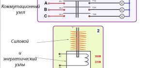
Contactors have
two types of contacts . Some contacts are power contacts that open or close power circuits, and others are control contacts for the contactor itself, i.e. directly give a command to close/open the power ones.
Control contacts A1-A2 are designated the same on all contactors. It is to them that voltage must be applied or removed so that the power contacts open or close.
Power contacts that turn on or off the load connected to the contactor are always in pairs 1-2, 3-4, 5-6, 7-8 , etc.
The number of pairs of power contacts for ABB magnetic starters is even, either two or four. They are designated either NO (normally open) or NC (normally closed). Those. when there is no voltage on the NO coil, they are open; when voltage is applied to the NO coil, they are closed, and NC, accordingly, is the opposite. There are different variations: 2NO (two open contacts), 3NO-1NC (three open + one closed), etc., and are indicated on the contactor body by the numbers 40 (four NO contacts), 20 (two NO contacts), 22 (two NO and two NC), 02 (two NC).
the ABB EN40-40N contactor it follows that this modular contactor is designed for a rated current of 40A and has four NO (normally open) contacts . It is also stated that the contactor coil is designed for 230V AC or DC.
To protect the contactor control coil, it is correct to install a circuit breaker in its circuit, etc. The power consumed by the coil is negligible, so it is better to take the rating of the machine no more than 1A.
The ESB 20A contactor occupies 1 module, 24A - 2 modules, 40 and 63A - 3 modules each on a DIN rail.
Contactors are also available with manual control, or more precisely with combined control. Those. You can use the switch to turn the modular contactor on and off with your hands by moving the lever. The photo below shows an ABB EN-40-4NO contactor with manual control.
Contactors, as well as other modular devices of the leading series ABB, Legrand, Schneider Electric, Hager, can have an additional contact . Just keep in mind that these are “not entirely full-fledged” contacts; they have a rated current of only up to 6A .
Below is an example of an additional contact for a Legrand contactor. The auxiliary contact actually has two contacts, one NC and one NO.
Connecting the modular contactor and the auxiliary contact is easy. The connection diagram between the devices is shown on the additional contact itself. It is important that the hole in the contactor and the “lever” of the auxiliary contact align exactly.
And this is what combined devices look like, including those already connected in the electrical panel.
Device and principle of operation
In the general sense of the word, a relay is an electrical mechanism that closes or breaks an electrical circuit based on certain electrical or other parameters that affect it.
Its non-switching design was invented back in 1831 by J. Henry. And two years later they began to use S. Morse to ensure the functioning of the telegraph.
Two main groups can be distinguished: electromechanical and electronic. In the first type of device, the work is carried out by a mechanism, and in the second, a printed circuit board with a microcontroller is responsible for everything. It is convenient to consider its operation using the example of an electromechanical relay, which is a pulse relay.
When choosing a relay operating mode, you must be guided by the frequency of switching on, the type and magnitude of the current, and the nature of the loads being tested.
Structurally, it can be represented as follows:
- A coil is a copper wire wound around a base of non-magnetic material. It can be insulated with fabric or coated with varnish that does not allow electricity to pass through.
- A core containing iron and activated by the passage of electric current through the turns of a coil.
- A movable armature is a plate that is attached to the armature and exerts an influence on the closing contacts.
- The contact system is a direct circuit state switch.
The operation of a relay is based on the phenomenon of electromagnetic force. It appears in the ferromagnetic core of the coil when current is passed through it. The coil in this case is a retractor device.
The core in it is connected to a movable armature, which activates the power contacts, carrying out switching. They can be of normally open/normally closed type. Sometimes a contact block may contain both open and closed types of connection.
When the circuit is turned on, the mechanism fixes this position, which changes when the pulse is applied again and is fixed again until the next change
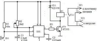
An additional resistor can be connected to the coil, which increases the accuracy of operation, as well as a semiconductor diode, which limits the overvoltage on the winding. In addition, the design may contain a capacitor installed parallel to the contacts to reduce sparking.
The operation of the device can be more clearly represented by dividing it into several blocks:
- the performer is a contact group that closes/opens the electrical circuit;
- intermediate - the coil, core and moving armature activate the executing unit;
- control - in this relay converts an electrical signal into a magnetic field.
Since a single electrical impulse is required to switch the position of the contacts, we can conclude that these devices consume voltage only at the moment of switching. This significantly saves energy, unlike conventional pass-through switches.
The second type of pulse relay is the electronic type. The microcontroller is responsible for its operation. The intermediate block here is a coil or semiconductor switch. The use of elements such as programmable logic controllers in the circuit makes it possible to supplement the relay, for example, with a timer.
This type of device has no mechanical moving elements. The work is carried out by a sensor that recognizes the control signal and solid-state electronics that switches the circuit
Modular contactor Legrand and Schneider Electric.
Legrand CX and Schneider Electric iCT contactors in purpose, noiselessness and technical characteristics to ABB , but they also have several advantages:
- The modular contactor ABB 40 and 63A has strictly 4 contacts, there is no less, and occupies three modules. Legrand and Schneider Electric have 40 and 63A contactors with only two contacts, which is sufficient for a single-phase electrical network, because They take up less space in the electrical panel (two modules), which is a whole module less than ABB.
- Such a modular contactor from Legrand or Schneider Electric, which takes up less space, and costs lessthan an ABB starter.
Thank you for your attention!
Connection diagrams
A pulse relay is used in circuits when the light is turned off from several points, for example, on the stairs, in different parts of the bedroom, dining room or other rooms.
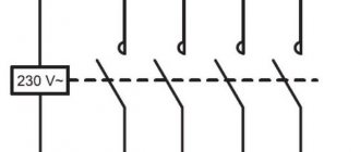
Let's look at the basic connection diagram:
- The phase from the machine goes to the 11th contact of the relay and push-button switches without fixing (the quantity may vary).
- Contact Y receives a control signal from the other side of the transfer switches.
- The potential from the 14th contact goes to the light bulb, and from it to the “neutral” bus with contacts and to the N pulse relay.
In another scheme, two groups of devices are already used - two switches, two pulse relays, two pairs of push-button switches with return and two pairs of groups of light bulbs.
The convenience of this scheme is that with the help of one switch you can turn off the lights in the entire apartment.
In combination with a motion sensor, it is possible to provide switching on/off when the appropriate control signal is supplied.
Connection options for a pulse relay may depend on the type, so detailed recommendations should be found in the manufacturer’s operating instructions.
Pulse relay. Controlling lighting in a house and apartment. Bistable light relay. Scheme
Schematic diagram.
What is the difference between a contactor and a magnetic starter
Very often contactors are confused with magnetic starters and this is justified, since in essence they are the same thing. These types of devices are structurally almost identical. The difference between these devices is in their purpose: if the contactor is a monoblock device, is a switch and mainly serves for switching circuits, then the electromagnetic relay (starter) also performs a protective function, for example, by emergency opening the circuit in case of overheating, and has several contactors, protective devices and control elements.
We recommend reading: Varistor: principle of operation, main characteristics, designation on the diagram
There is such a type of switching device as an intermediate relay - this is a low-power device that is used for switching in low-current circuits and can withstand many more opening cycles than a contactor.
How to connect the contact block correctly?
This block is installed on the top of the contactor, where there are special connectors with hooks.
The working circuit has two pairs of closed contacts, as well as two pairs of open connectors.
Normally open contact (NO) – when not working, it is always in the open position (pair 1-2). Therefore, for current to pass through it, it must be closed.
Normal closed contact (NC) - its non-working position is the closure of the connectors (pair 3-4). In this situation, when the contact opens, there will be no current through the magnetic starter.
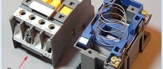
PM is a structure consisting of two basic fragments:
- top;
- lower
The upper part is a moving contact system, an arc-extinguishing chamber and a moving element of an electric magnet, connected to the connectors by the moving area of the mechanism.
The lower part consists of a winding, a return spring and a second fragment of the magnet body.
The role of the spring is to return the initial position of the upper region of the device, thus, in the absence of contact of the magnetic connector, there is no current in the winding.
Pulse sectional relay
The peculiarity of such devices is that using one button you can turn on different groups of light bulbs one by one or all at once.
For example, to control a chandelier with a large number of lamps, two wires are enough. In this case, you do not have to lay wiring to the device to the switch.
The device contains a connection diagram indicating two buttons and, accordingly, the possibility of control from two different points.
Let's look at the actions for each click:
- The first is to turn on the 1st group of light bulbs.
- The second is to supply voltage to the 2nd group of lamps and turn off the 1st.
- The third is to keep the second group on and add the 1st group to it (turning on all the lights).
- Fourth, turn off all the lights.