3.9
Average rating: 3.9
Total ratings received: 98.
3.9
Average rating: 3.9
Total ratings received: 98.
Electric current is the ordered movement of electrical charges or charged macroscopic bodies. The direction of the electric current I coincides with the direction of movement of positively charged particles: the charges move under the influence of the electric field that is created in the conductor as a result of the voltage U applied to the ends of the conductor. How does the magnitude of the current depend on the magnitude of the voltage? Let's try to figure it out.
Current value
By definition, current strength is a physical quantity equal to the amount of charge q passing through the cross section of the conductor during time t:
$$ I = { q\over t } $$
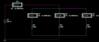
If the current strength does not depend on time, then such an electric current is called constant. Let us further consider just such a case when the current is constant. It is extremely difficult to measure the amount of charge, so in 1826 the German physicist Georg Ohm did the following: in an electrical circuit consisting of a voltage source (battery) and resistance, he measured the amount of current at different resistance values. Then, without changing the resistance value, he began to change the parameters of the voltage source, connecting, for example, two or three sources at once. By measuring the current in the circuit, he obtained the dependence of the current on the voltage U and on the resistance R.
Rice. 1. Current and voltage measurement circuit by Georg Ohm.
Volt-ampere characteristics
With its help, you can find out how the current changes when the voltage in the circuit increases or decreases. If it is built for a conductor, the dependence will be linear. This can be understood from Ohm's law, according to which the force is proportional to the applied potential difference. This type of graph is typical for metals. But at the same time, for semiconductors it will not be linear.
The thing is that such materials have special properties. A breakdown may occur in them - a phenomenon in which a sharp increase in current strength and a saturation process occur. In the latter case, the value of the electric current practically does not change with increasing voltage.
The dependence graph is constructed in a Cartesian coordinate system. The X axis represents voltage, and the Y axis represents current. You can study the characteristics for any circuit element yourself. To do this you will need to prepare:
- adjustable power supply;
- ammeter;
- voltmeter;
- element under study.
The circuit is assembled quite simply. A current meter (ammeter) is connected to the power supply, to the output of which a conductor is connected with one terminal. The second pole is connected to the free contact of the voltage source. The voltage meter is connected in parallel to the element being tested.
The experiment is as follows. Using the power supply, the voltage is changed, the value of which is read from the voltmeter. At the same time, data is written off from the ammeter. Then the coordinate axes of the current-voltage characteristics are drawn, on which the points of the corresponding quantities are plotted and connected by a smooth line. The drawn curve or straight line will display the real picture of the dependence of current on voltage for the element. Using the current-voltage characteristic, you can plot the dependence of power on current. To do this, you need to perform a calculation using the formula: P = I*U.
In practice, we often have to deal with alternating current. This is a phenomenon in which its strength changes over time. In this case, the current-voltage characteristic is not used, since the change in U occurs according to a certain law, most often sinusoidal, therefore, if you need to plot a graph of voltage versus time, you need to know the formula with which the function is described.
Ohm's law
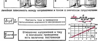
As a result of his research, Georg Ohm discovered that the ratio of the voltage U between the ends of a metal conductor, which is part of an electrical circuit, to the current strength I in the circuit is a constant value:
$$ R= { U \over I } $$
where R is electrical resistance. This formula is called Ohm's law, which is still the main calculation tool in the design of electrical and electronic circuits.
If we plot the voltage values along the abscissa axis, and the current values in the circuit at given voltage values along the ordinate axis, we will get a graph of the dependence of the current I on the voltage U.
Rice. 2. Graph of current versus voltage.
From this graph it is clear that this relationship is linear. The angle of inclination of the straight line depends on the amount of resistance. The larger R, the smaller the angle of inclination.
Rice. 3. Graph of current versus resistance.
If we fix the voltage U and plot the values R of the electrical resistance along the abscissa axis, then the resulting graph shows that this dependence is already nonlinear - with increasing resistance, the behavior of the current is described by an inversely proportional function - a hyperbola.
Ohm's law stops working at high current values, as additional effects associated with thermal heating of the substance and an increase in temperature begin to operate. In gases at high currents, breakdown occurs, the current grows like an avalanche, deviating from the linear law.
Relationship between parameters
For electric current to appear, several conditions must be met. We need a source of it, a material that has free charge carriers, and a closed circuit through which they can move. After the invention of the “voltaic column,” scientists began to conduct various experiments studying the flow of electric current. In 1825, Ohm, in his experiments using a galvanic source and torsion balances, observed the loss of energy in charges. He discovered that the current in a circuit depends not only on the type of material, but also on its linear characteristics.
Analyzing the data obtained, Ohm derived the formula: X = a*k/L, where: X is the electric current, a is the electrical voltage, k is the conductivity coefficient, l is the length of the material. Subsequently, this law was confirmed by other scientists and was named after the discoverer.
In its modern form it is written as follows: I = U/R, where:
- U—potential difference (voltage);
- R - resistance.
That is, the current strength in a conductor is directly proportional to the voltage and inversely proportional to its resistance. R is the proportionality coefficient. By its definition, it is the reciprocal of conductivity. Resistance depends on the physical dimensions of the conductor and its ability to prevent the passage of electric current.
The value of R can be calculated using the formula: R = pL/S, where p is the specific coefficient depending on the property of the material, L is the length of the conductor, S is the cross-sectional area. The resistivity value depends on temperature, but remains constant for each degree. Its value has been measured for almost all existing elements in nature and is tabulated.
Open formulas made it possible to establish not only the dependence of current on resistance, but also to connect 2 fundamental electrical quantities - force and work. Moreover, the relationship between them is usually depicted using a graph called the current-voltage characteristic. Its meaning is to construct a function described by Ohm's law. This is an important graph for electrical devices. Using it, you can determine the power for any value.
Units
In the International System of Units (SI), the unit of electrical resistance is called the “ohm” in honor of the physicist Georg Ohm. By definition, an electrical resistance of 1 ohm has a section of the circuit where the voltage drops 1 V at a current of 1 A.
$$ [1 Ohm] ={ [1 V]\over [1 A] } $$
The unit of measurement of resistivity is derived from the units of quantities included in the formula: resistance, length and area. That is, in the SI system it turns out that if R = 1 Ohm, S = 1 m2, and L = 1 m, then ρ = 1.
This is the unit of measurement for resistivity. But in practice it turned out that real wires have a cross-sectional area of much less than 1 m2. Therefore, when calculating ρ, it was decided to use the value of the area S in mm2 so that the final value has a compact form. Then we get more convenient (fewer zeros after the decimal point) numerical values of resistivity for perception:
$$ [ ρ ] = { [Ohm] * [mm^2] \over [m]} $$
The current value is measured with an ammeter, and the voltage value with a voltmeter. When making very accurate measurements, it is necessary to take into account the internal resistance of these devices.
Voltage measurement
To measure voltage, a voltmeter is used, although multimeters are now the most popular. A multimeter is a combined device that contains a lot of things. I wrote about it in an article and told how to use it.
A voltmeter is just a device that measures the potential difference between two points. The voltage (potential difference) at any point in the circuit is usually measured relative to ZERO or GROUND or MASS or MINUS of the battery. It doesn’t matter, the main thing is that it should be the point with the lowest potential in the entire circuit.
So, to measure the DC voltage between two points, we do the following. The black (negative) probe of the voltmeter is stuck into the point where we can presumably observe a point with a lower potential (ZERO). We stick the red probe (positive) into the point whose potential is interesting to us.
And the result of the measurement will be the numerical value of the potential difference, or in other words, voltage.
How to increase the current in the power supply?
On the Internet you can often come across the question of how to increase I in the power supply without changing the voltage. Let's look at the main options.
Situation No. 1.
A 12 Volt power supply operates with a current of 0.5 Amperes. How to raise I to its maximum value? To do this, a transistor is placed in parallel with the power supply. In addition, a resistor and stabilizer are installed at the input.
Find out more - how to check a transistor with a multimeter for serviceability.
When the voltage across the resistance drops to the required value, the transistor opens, and the rest of the current flows not through the stabilizer, but through the transistor.
The latter, by the way, must be selected according to the rated current and a radiator installed.
In addition, the following options are possible:
- Increase the power of all elements of the device. Install a stabilizer, a diode bridge and a higher power transformer.
- If there is current protection, reduce the value of the resistor in the control circuit.
Situation No. 2.
There is a power supply for U = 220-240 Volts (at the input), and at the output a constant U = 12 Volts and I = 5 Amperes. The task is to increase the current to 10 Amps. In this case, the power supply should remain approximately the same dimensions and not overheat.
Here, to increase the output power, it is necessary to use another transformer, which is converted to 12 Volts and 10 Amps. Otherwise, the product will have to be rewound yourself.
In the absence of the necessary experience, it is better not to take risks, because there is a high probability of a short circuit or burnout of expensive circuit elements.
The transformer will have to be replaced with a larger product, and the damper chain located on the DRAIN of the key will also have to be recalculated.
The next point is replacing the electrolytic capacitor, because when choosing a capacitance you need to focus on the power of the device. So, for 1 W of power there are 1-2 microfarads.
It is also recommended to change the diodes with rectifiers. In addition, it may be necessary to install a new rectifier diode on the low side and increase the capacitor capacity.
After such a modification, the device will heat up more, so installing a fan is not necessary.
What are the types of electric current in everyday life?
The shape of the current signal depends on the operation of the voltage source and the resistance of the medium through which the signal passes. Most often in practice, a home craftsman has to deal with the following types:
- a constant signal generated from batteries or galvanic cells;
- sinusoidal, created by industrial generators with a frequency of 50 hertz;
- pulsating, formed by transformations of various power supplies;
- pulsed, penetrating into the household network due to lightning discharges into overhead power lines;
- arbitrary.
The most common type is sinusoidal or alternating current: it powers all our devices.
Many semiconductor household appliances operate in modern wiring powered by sinusoidal voltage. They have non-linear resistance and violate the harmonic shape.
These noises accumulate throughout the entire circuit from a specific consumer to the supply transformer, distorting the ideal sine wave in an arbitrary manner. As a result, both the shape and magnitude of the supply voltage changes.
This can lead to the creation of an emergency mode: burning out of the neutral conductor in the three-phase supply circuit. This process is described in detail in a separate article on another site.
Serial and parallel connection of elements
For elements of an electrical circuit (section of a circuit), a characteristic point is a serial or parallel connection. Accordingly, each type of connection is accompanied by a different pattern of current flow and voltage supply. In this regard, Ohm's law is also applied differently, depending on the option of including elements.
Circuit of series-connected resistive elements
In relation to a series connection (a section of a circuit with two components), the following formulation is used:
- I = I1= I2 ;
- U = U1+ U2 ;
- R = R1+ R2
This formulation clearly demonstrates that, regardless of the number of resistive components connected in series, the current flowing through a section of the circuit does not change in value. The magnitude of the voltage applied to the effective resistive components of the circuit is the sum and totals the value of the emf source.
In this case, the voltage on each individual component is equal to: Ux = I * Rx. The total resistance should be considered the sum of the values of all resistive components in the circuit.
Circuit of parallel connected resistive elements
In the case when there is a parallel connection of resistive components, the following formulation is considered fair in relation to the law of the German physicist Ohm:
- I = I1+ I2 … ;
- U = U1= U2 … ;
- 1 / R = 1 / R1+ 1 / R2 + …
Options for creating circuit sections of a “mixed” type, when parallel and serial connections are used, are not excluded. For such options, the calculation is usually carried out by initially calculating the resistive rating of the parallel connection. Then the value of the resistor connected in series is added to the result obtained.
General information
Any physical body consists of molecules and atoms. These particles interact with each other. They can attract each other or repel each other. In an isolated system, elementary particles are charge carriers. In a quiet state, that is, when there is no external influence on the body, the algebraic sum of the particle energy is always a constant value. This statement is called the law of conservation of electric charge.
Particles can move randomly along the crystal lattice, but their movement is compensated. Therefore, no current occurs. But if an external force is applied to the body, then the free electrons begin to move in one direction. This ordered movement of charged particles is called electric current. It can be quantitatively described through force.
Ordered charges are forced to move by an electric field, along the lines of which movement occurs. This term was first introduced by Faraday. He was able to find out that around any carrier there is a special type of matter that affects the behavior of other particles. The force characteristic of the electric field was taken to be the ratio of the acting force to the magnitude of the charge placed at a given point: E = F / q. We called this characteristic tension.
The study of the field made it possible to experimentally discover the principle of superposition. That is, to establish that the field strength created by a system of charges is equal to the geometric sum of the values existing for individual carriers: E = Σ E1 + E2 +…+ En. Tension is directly proportional to voltage, which in turn is equal to the potential difference between two points.
Essentially, this is the work done by an electric field to transfer a unit charge from one place to another: U = A / q = E * d, where d is the distance between points. The voltage value depends on several factors:
- body structure;
- temperature;
- resistance.
The last value has the greatest influence. It characterizes the ability of a material to prevent the passage of current, that is, it determines conductivity. Resistance depends on the length of the conductor and its cross-section: R = (p * l) / S, where p is the inverse parameter of conductivity (reference value). It is numerically equal to the resistance of a homogeneous conductor of unit length and cross-sectional area.
Resistors, current and voltage
In this article we will look at a resistor and its interaction with the voltage and current passing through it. You will learn how to calculate a resistor using special formulas. The article also shows how special resistors can be used as a light and temperature sensor.
The idea of electricity
A beginner should be able to imagine electric current. Even if you understand that electricity consists of electrons moving through a conductor, it is still very difficult to visualize clearly. That's why I offer this simple analogy with a water system that anyone can easily imagine and understand without delving into the laws.
Notice how electric current is similar to the flow of water from a full tank (high voltage) to an empty tank (low voltage). In this simple analogy of water and electric current, a valve is analogous to a current limiting resistor. From this analogy we can derive some rules that you must remember forever: - As much current flows into a node, so much flows out of it - In order for current to flow, there must be different potentials at the ends of the conductor. — The amount of water in two vessels can be compared to the charge of a battery. When the water level in different vessels becomes the same, it will stop flowing, and when the battery is discharged, there will be no difference between the electrodes and the current will stop flowing. - The electric current will increase as the resistance decreases, just as the speed of water flow will increase as the valve resistance decreases.
I could write many more inferences based on this simple analogy, but they are described in Ohm's law below.
Resistor
Resistors can be used to control and limit current, hence the main parameter of a resistor is its resistance, which is measured in Ohms . We should not forget about the power of the resistor, which is measured in watts (W), and shows how much energy the resistor can dissipate without overheating and burning out. It is also important to note that resistors are not only used to limit current, they can also be used as a voltage divider to produce a lower voltage from a higher voltage. Some sensors are based on the fact that resistance varies depending on illumination, temperature or mechanical impact; this is written in detail at the end of the article.
Ohm's law
It is clear that these 3 formulas are derived from the basic formula of Ohm's law, but they must be learned to understand more complex formulas and diagrams. You should be able to understand and imagine the meaning of any of these formulas. For example, the second formula shows that increasing the voltage without changing the resistance will lead to an increase in current. However, increasing the current will not increase the voltage (even though this is mathematically true) because voltage is the potential difference that will create electric current, not the other way around (see the 2 water tank analogy). Formula 3 can be used to calculate the resistance of a current limiting resistor at a known voltage and current. These are just examples to show the importance of this rule. You will learn how to use them yourself after reading the article.
Series and parallel connection of resistors
Understanding the implications of connecting resistors in parallel or in series is very important and will help you understand and simplify circuits with these simple formulas for series and parallel resistance:
In this example circuit, R1 and R2 are connected in parallel, and can be replaced by a single resistor R3 according to the formula: In the case of 2 resistors connected in parallel, the formula can be written as follows:
In addition to being used to simplify circuits, this formula can be used to create resistor values that you don't have. Note also that the value of R3 will always be less than that of the other 2 equivalent resistors, since adding parallel resistors provides additional paths for electrical current, reducing the overall resistance of the circuit.
Series-connected resistors can be replaced by a single resistor, the value of which will be equal to the sum of these two, due to the fact that this connection provides additional current resistance. Thus, the equivalent resistance R3 is very simply calculated: R3=R1+R2
There are convenient online calculators on the Internet for calculating series and parallel connections of resistors.
Current limiting resistor
The most basic role of current limiting resistors is to control the current that will flow through a device or conductor. To understand how they work, let's first look at a simple circuit where the lamp is directly connected to a 9V battery. A lamp, like any other device that consumes electricity to perform a specific task (such as emitting light), has an internal resistance that determines its current consumption. Thus, from now on, any device can be replaced by an equivalent resistance.
Now that the lamp will be considered as a resistor, we can use Ohm's law to calculate the current passing through it. Ohm's law states that the current passing through a resistor is equal to the voltage difference across it divided by the resistance of the resistor: I=V/R or more precisely: I=(V1-V2)/R where (V1-V2) is the voltage difference to and after the resistor.
Now look at the picture above where a current limiting resistor has been added. It will limit the current going to the lamp, as the name suggests. You can control the amount of current flowing through the lamp simply by selecting the correct R1 value. A large resistor will reduce the current greatly, while a small resistor will reduce the current less strongly (same as in our water analogy).
Mathematically it will be written like this:
It follows from the formula that the current will decrease if the value of R1 increases. Thus, additional resistance can be used to limit the current. However, it is important to note that this causes the resistor to heat up, and you must correctly calculate its power, which will be discussed later.
You can use an online calculator to calculate the current limiting resistor of an LED.
Resistors as a voltage divider
As the name suggests, resistors can be used as a voltage divider, in other words, they can be used to reduce voltage by dividing it. Formula:
If both resistors have the same value (R1=R2=R), then the formula can be written as follows:
Another common type of divider is when one resistor is connected to ground (0V), as shown in Figure 6B. Replacing Vb with 0 in formula 6A, we get:
Nodal analysis
Now, when you start working with electronic circuits, it is important to be able to analyze them and calculate all the necessary voltages, currents and resistances. There are many ways to study electronic circuits, and one of the most common methods is the nodal method, where you simply apply a set of rules and calculate, step by step, all the necessary variables.
Simplified rules for nodal analysis
Node Definition
A node is any connection point in a chain. Points that are connected to each other, without other components in between, are treated as a single node. Thus, an infinite number of conductors to one point are considered one node. All points that are grouped into one node have the same voltages.
Branch Definition
A branch is a collection of 1 or more components connected in series, and all components that are connected in series to that circuit are considered as one branch.
All voltages are usually measured relative to ground, which is always 0 volts.
Current always flows from a node with a higher voltage to a node with a lower one.
The voltage at the node can be calculated from the voltage near the node, using the formula: V1-V2=I1*(R1) Let's move: V2=V1-(I1*R1) Where V2 is the desired voltage, V1 is the reference voltage, which is known, I1 current flows from node 1 to node 2 and R1 represents the resistance between the 2 nodes.
In the same way as in Ohm's law, the branch current can be determined if the voltage of 2 adjacent nodes and the resistance is known: I 1 = (V1-V2)/R1
The current input current of a node is equal to the current output current, so it can be written as: I 1+ I3=I2
It is important that you are able to understand the meaning of these simple formulas. For example, in the figure above, current flows from V1 to V2, and therefore the voltage of V2 should be less than V1. By using the appropriate rules at the right time, you can quickly and easily analyze and understand the circuit. This skill is achieved through practice and experience.
Calculation of the required resistor power
When purchasing a resistor, you may be asked the question: “What power resistors do you want?” or they can just give 0.25W resistors as they are the most popular. As long as you are working with resistances greater than 220 ohms and your power supply is providing 9V or less, you can work with 0.125W or 0.25W resistors. But if the voltage is more than 10V or the resistance value is less than 220 ohms, you must calculate the power of the resistor, or it may burn out and ruin the device. To calculate the required resistor power, you must know the voltage across the resistor (V) and the current flowing through it (I): P=I*V where current is measured in amperes (A), voltage in volts (V) and P is power dissipation in watts (W)
The photo shows resistors of various powers, they mainly differ in size.
Types of resistors
Resistors can be different, ranging from simple variable resistors (potentiometers) to ones that respond to temperature, light and pressure. Some of them will be discussed in this section.
Variable resistor (potentiometer)
The above figure shows a schematic representation of a variable resistor. It is often referred to as a potentiometer because it can be used as a voltage divider.
They vary in size and shape, but they all work the same way. The terminals on the right and left are equivalent to a fixed point (such as Va and Vb in the figure above left), and the middle terminal is the moving part of the potentiometer and is also used to change the resistance ratio of the left and right terminals. Therefore, a potentiometer is a voltage divider that can be set to any voltage from Va to Vb. Additionally, a variable resistor can be used as a current limiting resistor by connecting the Vout and Vb pins as in the figure above (right). Imagine how the current will flow through the resistance from the left terminal to the right until it reaches the moving part, and flows along it, while very little current flows to the second part. So you can use a potentiometer to adjust the current of any electronic components, such as a lamp.
LDR (Light Sensing Resistors) and Thermistors
There are many resistor-based sensors that respond to light, temperature or pressure. Most of them are included as part of a voltage divider, which varies depending on the resistance of the resistors, which changes under the influence of external factors.
Thermistors
Photoresistor (LDR)
As you can see in Figure 11A, photoresistors vary in size, but they are all resistors whose resistance decreases when exposed to light and increases in darkness. Unfortunately, photoresistors react rather slowly to changes in light levels and have fairly low accuracy, but are very easy to use and popular. Typically, the resistance of photoresistors can vary from 50 ohms in the sun, to more than 10 megohms in absolute darkness.
As we already said, changing the resistance changes the voltage from the divider. The output voltage can be calculated using the formula:
If we assume that the LDR resistance varies from 10 MΩ to 50 Ω, then Vout will correspondingly be from 0.005V to 4.975V.
A thermistor is similar to a photoresistor, however, thermistors have many more types than photoresistors, for example, a thermistor can be either a negative temperature coefficient (NTC) thermistor, whose resistance decreases with increasing temperature, or a positive temperature coefficient (PTC), whose resistance will increase with increasing temperature. Now thermistors respond to changes in environmental parameters very quickly and accurately.
Circuit designation of resistors
You can read about determining the resistor value using color coding here.
Original article
Tags:
- Translation