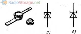
Thyristor
A thyristor is a switching semiconductor device that passes current in one direction.
This radio element is often compared to a controlled diode and is called a semiconductor controlled rectifier (SCR). The thyristor has three outputs, one of which - the control electrode, one might say, the “trigger” - is used to abruptly switch the thyristor to the on state.
The thyristor combines the functions of a rectifier, switch and amplifier. It is often used as a regulator, mainly when the circuit is powered by alternating voltage. The following points reveal the four main properties of a thyristor:
- A thyristor, like a diode, conducts in one direction, acting as a rectifier;
- The thyristor is switched from the off state to the on state when a signal is applied to the control electrode and, therefore, like a switch, has two stable states. However, to return the thyristor to the off (open) state, special conditions must be met;
- the control current required to transfer the thyristor from a closed state to an open state is significantly less (several milliamps) with an operating current of several amperes and even several tens of amperes. Consequently, the thyristor has the properties of a current amplifier;
- oThe average current through a load connected in series with a thyristor can be precisely adjusted depending on the duration of the signal at the control electrode. The thyristor is a power regulator.
What is a thyristor, its structure and designation on the diagram
A thyristor is a semiconductor element that has only two states: “open” (current flows) and “closed” (no current). Moreover, both states are stable, that is, the transition occurs only under certain conditions. The switching itself occurs very quickly, although not instantly.
In terms of its mode of action, it can be compared to a switch or a key. But the thyristor switches using voltage, and turns off when the current is lost or the load is removed. So the operating principle of a thyristor is not difficult to understand. You can think of it as an electrically controlled key. Well, not really.
A thyristor usually has three outputs. One control and two through which current flows. You can try to briefly describe the principle of operation. When voltage is applied to the control output, the circuit is switched through the anode-collector. That is, it is comparable to a transistor. The only difference is that in a transistor, the amount of current passed depends on the voltage applied to the control terminal. And the thyristor is either completely open or completely closed.
Thyristor structure
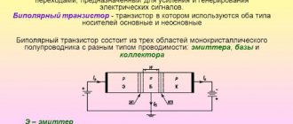
A thyristor is a controlled three-electrode semiconductor device consisting of alternating four silicon layers of type p and n. A semiconductor device with a four-layer structure is shown in Fig. 1.
The extreme region of the p-structure, to which the positive pole of the power source is connected, is usually called the anode, and the extreme region n, to which the negative pole of this source is connected, is called the cathode.
Fig.1. Thyristor structure and designation
Equivalent replacement of lambda diodes
Semiconductor devices such as lambda diodes and tunnel diodes . The current-voltage characteristics of these devices have an N-shaped section.
Lambda diodes and tunnel diodes can be used to generate and amplify electrical signals. In Fig. 8 and fig. Figure 9 shows circuits simulating lambda di-od [RTE 9/87-35].
In practice, generators often use the circuit shown in Fig. 9 [PTE 5/77-96]. If a controlled resistor (potentiometer) or transistor (field-effect or bipolar) is connected between the drains of the field-effect transistors, then the type of current-voltage characteristic of such a “lambda diode” can be controlled within wide limits: adjust the generation frequency, modulate high-frequency oscillations, etc.
Rice. 8. Analog of a lambda diode.
Rice. 9. Analog of a lambda diode.
Properties of the thyristor in the closed state
According to the structure of the thyristor, three electron-hole junctions can be identified and the thyristor can be replaced with an equivalent circuit, as shown in Fig. 2.
This equivalent circuit allows us to understand the behavior of the thyristor with the control electrode disconnected.
If the anode is positive with respect to the cathode, then diode D2 is closed, which leads to the closure of the thyristor, which in this case is forward biased. With a different polarity, diodes D1 and D2 are reverse biased, and the thyristor is also turned off.
Fig.2. Representation of a thyristor by three diodes
Opening principle using a control electrode
An equivalent representation of the p-npn structure in the form of two transistors is shown in Fig. 3.
Representing a thyristor in the form of two transistors of different conductivity types leads to the equivalent circuit shown in Fig. 1.4. It clearly explains the phenomenon of thyristor unlocking.
Let us set the current IGT through the control electrode of the thyristor, biased in the forward direction (voltage VAK positive), as shown in Fig. 4.
Since the IGT current becomes the base current of the npn transistor, the collector current of this transistor is equal to B1xIGT, where B1 is the current gain of transistor T1.
This current is also the base current of the pnp transistor, which leads to its unlocking. The collector current of transistor T2 is B1xB2xIGT and is summed with the current IGT, which maintains transistor T1 in the open state. Therefore, if the IGT drive current is large enough, both transistors will go into saturation.
The internal feedback circuit maintains the conductivity of the thyristor even if the initial current of the IGT control electrode disappears, while the anode current (1A) remains quite high.
A typical thyristor startup circuit is shown in Fig. 5
.
Fig.3. Splitting a thyristor into two transistors
Fig.4. Representation of a thyristor as a two-transistor circuit
Fig.5. Typical thyristor trigger circuit
Some features of Hi-Com triacs
Hi-Com triacs have a different internal structure from conventional triacs. One difference is that the two halves of the thyristor are better isolated from each other, which reduces their mutual influence. This provides the following benefits:
- Increasing the permissible dVCOM/dt value. This makes it possible to control reactive loads (in most cases) without the use of a damping device, without switching failures. This reduces the number of components, PCB size, cost, and eliminates energy dissipation losses from the damping device.
- Increasing the permissible dICOM/dt value. This significantly improves performance at higher frequencies and for non-sinusoidal voltages without the need to limit dICOM/dt using inductance in series with the load.
- Increasing the permissible dVD/dt value. Triacs are very sensitive at high operating temperatures. A high dVD/dt reduces the tendency for spontaneous switching from a non-conducting state to occur at the expense of dV/dt at high temperatures. This allows them to be used at high temperatures to drive resistive loads in kitchen or heating applications where conventional triacs cannot be used.
Due to the special internal structure, operation of Hi-Com triacs in quadrant 3+ is impossible. In most cases this is not a problem since it is the least desirable and least used quadrant. Therefore, replacing a conventional triac with a Hi-Com is almost always possible.
More detailed information on Hi-Com Triacs can be found in Philips specific documentation: “Factsheet 013 - Understanding Hi-Com Triacs” and “Factsheet 014 - Using Hi-Com Triacs”.
Thyristor shutdown
The thyristor will go into the closed state if no signal is applied to the control electrode of the open thyristor, and its operating current drops to a certain value called the holding current (hypostatic current).
The thyristor will turn off, in particular, if the load circuit was open (Fig. 6a) or the voltage applied to the external circuit changed polarity (this happens at the end of each half-cycle of the alternating supply voltage).
Fig.6. Methods for turning off a thyristor
When the thyristor operates at constant current, switching off can be done using a mechanical switch.
Connected in series with the load, this switch is used to disconnect the operating circuit.
A switch connected in parallel to the main electrodes of the thyristor (Fig. 6b) shunts the anode current, and the thyristor goes into the closed state. Some thyristors turn on again after the switch is opened. This is explained by the fact that when the switch is opened, the parasitic capacitance of the p-n junction of the thyristor is charged, causing interference.
Therefore, they prefer to place the switch between the control electrode and the cathode of the thyristor (Fig. 1.6c), which guarantees correct shutdown by cutting off the holding current. At the same time, the p-n junction corresponding to diode D2 from the thyristor equivalent circuit with three diodes is reverse-biased (Fig. 2).
In Fig. 6a-e show various options for thyristor shutdown circuits, including those previously mentioned. Others are usually used when it is necessary to turn off the thyristor using an additional circuit. In these cases, the mechanical switch can be replaced by an auxiliary thyristor or a key transistor, as shown in Fig. 7.
Fig.7. Classic thyristor shutdown circuits using an additional circuit
Conductivity state, dIT/dt
When a triac (thyristor) is in conduction state under the influence of a gate signal, conduction begins in the region of the crystal adjacent to the gate and then quickly spreads to the active region. This delay imposes a limit on the permissible rate of rise of the load current. A high dIT/dt value may cause the device to burn out, resulting in a short circuit between T1 and T2.
When operating in quadrant 3+, the allowed dIT/dt value is further reduced due to the transition structure. This can lead to an instant avalanche process in the gate and burnout during a rapid rise in current. Destruction of the triac may not occur immediately, but with gradual burnout of the Gate-T1 junction, which will lead to a short circuit after several turns on. Sensitive triacs are most susceptible to this. These problems do not apply to Hi-Com triacs, since they do not operate in quadrant 3+.
The dIT/dt value is related to the gate current slew rate (dIG/dt) and the maximum IG value. High dIG/dt and peak IG values (without exceeding the rated gate power) result in a higher dIT/dt value.
The simplest example of a load that produces a high initial inrush current is an incandescent light bulb, which has low resistance when cold. For resistive loads of this type, the dIT/dt value will reach its maximum value when the transition to conduction begins at the peak of the mains voltage. If there is a possibility that the dIT/dt of the triac will be exceeded, this must be limited by placing an inductor or ITC thermistor in series with the load.
The inductor should not saturate during the maximum current peak. To limit the dIT/dt value, a coreless inductor must be used.
There is a better solution with which you can avoid the need to connect current-limiting devices in series with the load. It consists of using the switching mode at zero potential difference. This would give a smooth increase in current from the beginning of the half-wave.
Note: It is important to remember that the zero potential switching mode only applies to resistive loads. Using the same method for reactive loads, where there is a phase shift between voltage and current, can cause unipolar conduction, leading to possible saturation of inductive loads, destructively high current, and overheating. In this case, a more advanced zero current switching method or turn-on phase control circuit is required.
Triac
SIMCMOP is a semiconductor device that is widely used in systems powered by alternating voltage. In simple terms, it can be considered as a controlled switch. When closed, it behaves like an open switch. On the contrary, the supply of control current to the control electrode of the triac leads to its transition to a conducting state. At this time, the triac is like a closed switch.
In the absence of control current, the triac inevitably passes from the conduction state to the closed state during any half-cycle of the alternating supply voltage.
In addition to operating in relay mode in a thermostat or photosensitive switch, control systems have been developed and are widely used that operate on the principle of phase control of the load voltage, or, in other words, smooth regulators.
Purpose of the device
Thyristors are semiconductor devices with three (or more) pn junctions intended for use as electronic switches in electrical current switching circuits. They switch electrical circuits, regulate voltage, and convert direct current into alternating current.
In design and principle of operation, it is very similar to a semiconductor diode, but unlike it, the thyristor is controlled. The “key” nature of the action of the trinistor allows it to be used for switching electrical circuits where previously only electromagnetic relays served for this purpose.
Semiconductor switches are lighter, more compact and many times more reliable in operation than electromagnetic relays with mechanically closed contacts. Unlike such relays, they switch at a very high speed - hundreds and thousands of times per second, and if necessary - even faster. SCRs are used in modern electrical communication equipment, in high-speed remote control systems, in computers and in energy devices.
Triac unlocking
In alternating power mode, a change in the states of the triac is caused by a change in the polarity of the voltage on the working electrodes A1 and A2. Therefore, depending on the polarity of the control current, four options for controlling the triac can be defined, as shown in Fig. 9.
Each quadrant corresponds to one way of opening the triac. All methods are briefly described in table. 1.
Fig.9. Four possible triac control options
Table 1. Simplified representation of methods for opening a triac
| Quadrant | VA2-A1 | VG-A1 | I.G.T. | Designation |
| I | >0 | >0 | Weak | + + |
| II | >0 | Average | + — | |
| III | Average | — — | ||
| IV | >0 | High | — + |
For example, if a voltage VA1-A2>0 is applied between the working electrodes of a triac and the voltage on the control electrode is negative with respect to the anode A1, then the bias of the triac corresponds to quadrant II and the simplified designation + -.
For each quadrant, the unlocking current I from (IGT), the holding current Iud (In) and the switching current Ioff (IL) are determined.
The unlocking current must be maintained until the operating current exceeds two to three times the holding current In. This minimum unlocking current is the turn-on current of the triac IL.
Then, if the current through the control electrode is removed, the triac will remain in a conducting state as long as the anode current exceeds the holding current In.