In this article we will look at various options for time delay relay circuits with a supply voltage of 220 Volts. The principle of operation of such a device is that when a start event occurs: pressing a button or turning on the power supply, the device connects the load to the network.
After the specified time has passed, the load is turned off and is not turned on again until the next starting event occurs.
There are many different circuit solutions for such 220 Volt turn-off time relays. Let's first look at what options are possible.
Firstly, they are divided into:
- with galvanic isolation;
- without galvanic isolation.
The former are safer and more expensive; the second are less safe, but cheaper.
Secondly, by the type of output element that switches the load:
- relay (“dry contact” - switching, turning on, turning off or a group of contacts);
- triac;
- thyristor.
The first option is the least sensitive to the type of connected load and is resistant to current surges; triac - less reliable and sensitive to inductive load; and a thyristor cannot switch a 220V sinusoidal voltage, so as a rule it controls only half-wave. Using a thyristor, you can control a load that is insensitive to the shape of the supply voltage.
You can also divide the types of circuit solutions into:
- constant holding time;
- adjustable exposure time (timer).
Next, we will look at 2 options for a relay circuit: a very simple option or a more complex, but professional level one.
How to choose?
When choosing a specific time relay model, you must be guided by the following principles regarding their parameters:
- Type and value of operating voltage - various models can either be connected to a household network of 220 V AC, or operate from reduced control circuits of 12, 42, 127 V, etc.
- Allowable load current – determines the capacity of the time relay contacts without overheating.
- The range of contact response times and the sensitivity of adjusting this parameter determines the speed at which the time relay is switched on, the possibility of changing it within any limits and the possible adjustment step.
- Design features and principle of operation - if local conditions do not allow classical switching of contacts for reasons of explosion hazard, it is necessary to install contactless models.
- Moisture resistance and temperature range - determines the permissible environmental parameters in which this time relay can be operated.
- Type of device (cyclic or intermediate) - the first of them sets a certain periodicity of the output signal, and the second acts as an intermediate link that provides a time delay in an already existing circuit.
Main characteristics of the device
A switch with a timer is a multifunctional device that allows you to save electricity.
A switch with a time relay makes it possible to expediently and economically consume electrical energy, performing a resource-saving function. This smart device is equipped with an integrated program, thanks to which users can set the operating parameters of lighting and energy-dependent devices.
The circuit breaker must meet the following characteristics:
- Have extremely long time parameters for which you can program it. The larger the time range, the more functions the device can perform.
- To have a high level of accuracy taking into account time intervals, to avoid errors in operation regarding the fact that the relay is activated - an on/off device.
- Have low discreteness, high resistance to voltage fluctuations, operate in the 230 V range with a current rating of 16A.
- Have sufficient functionality to configure various tasks to optimize the consumption of electrical resources. Support a different type of switching.
A switch with a delayed shutdown is a high-tech electronic device with a set of integrated programs. The device base consists of microcontrollers, relays, rectifier diode and resistors, which are needed to create intelligent lighting control.
The devices perform a lot of functions:
- turn on and off lighting, both indoor and outdoor;
- monitor the operating modes of volatile devices;
- maintain the microclimate in the rooms at the established level;
- guarantee heating on/off automatically;
- turn on/off the fan and security system elements;
- regulate the operating modes of advertising billboards;
- control the life support systems of large aquariums;
- manage watering and irrigation systems.
The automatic switch creates the effect of the presence of the home owners. This is additional protection against unauthorized intrusions.
Programming microprocessor devices
As described earlier, microprocessor devices became a milestone in the development of time relays. The essence of what they are needed for is the versatility of the device. It can be programmed to perform the functions of turning off, turning on, maintaining line activity for a set period, and all of the above can be done without changing the design of the device itself. Any complexity of operations will be performed using just one microcircuit located on the device board.
In addition to these features, a nice bonus is the expansion of functionality through communication interfaces with smart home systems. The latter can not only monitor the state of the time relay, but also set its parameters or directly influence the shutdown mechanisms.
For example, a universal two-channel programmable time relay UT24 from the Aries production association is shown in the picture below:
To program its timers, you need to refer to the block diagram and follow the steps; you can find out the purpose of the configured item in the user manual, which comes with each device:
As you can see, microprocessor devices seem complex only at first glance, but once you understand a little, you can easily use them for your purposes and configure them.
Types of switches equipped with a timer
The principle of operation of timers is to connect and disconnect contacts that control the light in a specific sequence.
There are two types of devices on the market, depending on the design and operating principle. In addition, switches are divided depending on the type of installation - hidden or external. Taking into account the connection of contacts in the mechanism - a screw or plate. All switches with a timer are powered by electricity, but the timer itself can be either mechanical or electronic.
With mechanical timer
The design petals determine the operating features of the mechanism. To start it, the user sets the time on the switch body. One petal corresponds to a 15 or 30 minute time interval. The rotating dial adjusts the timer setting. During the specified period of time, the consumer will receive electricity; as soon as the timer goes off, its supply will be cut off automatically.
Despite its simple design, the product has its drawbacks:
- Random mode is not allowed.
- It is impossible to assign complex tasks to the device.
- The countdown timer is not as accurate as in other models.
Mechanical models can be powered by backup batteries.
With electronic timer
It is assumed that there is a weekly programming interval for the device. The required time is set on the liquid crystal screen.
- The screen displays information about the setting options.
- The control device has several function buttons.
- Has up to 150 options.
- Low dispersion up to a minute.
- Installation is carried out on your own.
The electronic model has a large list of advantages and is in demand among users, because it ensures multitasking and accurate execution of all commands.
Self-production
If you wish, you can make a timer for turning on and off electrical appliances with your own hands. Before you begin, you need to decide on the tasks, find the device diagram and the required radio components. Schemes exist of varying degrees of complexity.
Transistor relay circuit
A simple 12 V turn-off delay relay circuit is assembled on a single transistor and does not contain scarce parts. This is a very easy to follow pattern. After assembly, no configuration is required. Such a device will work no worse than one purchased in a store.
Any npn conductivity transistor is used as VT1. When power is applied, the capacitor is charged. When the voltage threshold is reached, the transistor opens and relay K1 is activated. By changing the value of C1 and R2, the on time is adjusted. The switch-on delay in this design reaches 10 seconds. In order for the relay to remain closed for some time when the power is removed, a large capacitor is installed in parallel with the power supply to the circuit.
On-chip delay control
A simple circuit for controlling a light, fan, or other load can be assembled on the NE555. The NE555 specialized chip is nothing more than a timer. The output current of the device is 200 mA, the current consumption is 203 mA. The timer error does not exceed one percent and does not depend on changes in the signal in the 220 volt network.
The circuit operates from a constant voltage source. The circuit power signal level is selectable in the range from 9 to 14 Volts. A chain consisting of resistors R2, R4 and capacitor C1 sets the delay time. You can calculate this time using the formula t = 1.1*R2*R4*C1. After pressing the SB1 button, contacts K1.1 are closed. After time t they will open. In order for the timer to start counting time not from the moment the button is pressed, but at the moment it is released, you will need to use a button with normally closed contacts.
The adjustment time can be easily adjusted using variable resistor R2. It is convenient to assemble such a circuit on a board made of PCB or getinax. After correct assembly and with working radio components, the circuit works immediately.
Let's move on to the principle of operation of the circuit
After power is applied, the R1–C3 chain generates a starting pulse with a duration of approximately 100 ms for the DD1 microcircuit, from which the OUT output of the microcircuit is set to log.1, thereby turning on the optosimistor VS1, the triac VS2 and connecting the load to the 220V network. From this moment the countdown begins.
The delay time of the timer is set by the chain R3–R6–C2. The charging time of capacitor C2 to the shutdown voltage, the output OUT of the DD1 microcircuit to logical 0 is determined by the formula:
t = 1.1*(R3+R6)*C2
Resistor R6 limits the minimum delay time to 3 seconds. Capacitor C1 is necessary to filter noise in the power supply of the DD1 chip and should be located as close to it as possible.
Resistor R4 sets the LED current of the optosimistor and when using MOC3043 analogues, for example MOC3042 or MOC3041, it should be reduced, since they require more current to operate.
This circuit can also be used for switching starters, but keep in mind that in cases of low current starters, false operation or their buzzing in off mode is possible, since they can be switched on through the R5–C5 chain. In this case, this chain requires correction according to denominations.
Please note that the part of the circuit responsible for obtaining a constant voltage of 12 V can be replaced with a ready-made power supply (power adapter) with an output voltage of 12 V.
Such a device can be purchased immediately ready-made, or you can use an unnecessary one from any device: router, modem, phone or the like. In this case, the relay design will be significantly simplified.
Transformer T1 can be replaced with any other one with a rated input voltage of 220 Volts and an output voltage of 12 Volts.
If the turn-off delay relay circuit interests you and you would like to download a file with an image of the printed circuit board, leave your comments.
Time relay for automatic load shedding
Sometimes it is necessary to turn off the receiver or backlight after a certain period of time. This problem can be solved by the circuit shown in Fig. 1.
Rice. 1. Timer circuit for automatic load shutdown.
With the ratings of the timing elements indicated in the diagram, the shutdown delay will be about 40 minutes (for micropower timers, this time can be significantly increased, since they allow R2 to be set with a higher rating).
In standby mode, the device does not consume power, since transistors VT1 and VT2 are locked. Switching on is done by button SB1 - when pressed, transistor VT2 opens and supplies power to the microcircuit. At the output of timer 3, a voltage appears, which opens the transistor switch VT1 and supplies voltage to the load, for example, to the BL1 lamp.
The button is blocked, and the circuit will remain in this state while capacitor C2 is charging, after which it will turn off the load. Resistor R3 limits the discharge current of the timing capacitor, which increases the reliability of the device. To obtain large delay intervals, capacitor C2 must be used with a low leakage current, for example tantalum from the K52-18 series.
What else is important to know? 2 interesting facts
3T=RC
The considered formula T=RC has a certain peculiarity. Time T is only 63% of the maximum charge, 95% is 3T.
Voltage versus time
During discharge, an inversely proportional relationship occurs. During time T, the capacitor will discharge to 37%, after 3T to 5% of the maximum. This happens because with an increase or decrease in the internal charge, the potentials gradually equalize.
That is, let’s assume that in 10 seconds the condenser is charged to 95%. Charging voltage 10V, circuit resistance 10Ohm, current 1A. At the seventh second, the voltage in the circuit will drop by 30% and become 7V. This happens because the potential begins to equalize as the capacitor charges. Consequently, the current in the circuit will also drop by 30% - to 0.7A. And this will happen until equilibrium is established in the chain.
AC voltage
Sinusoidal voltage has several phases. At the peak of the ascent, when the half-cycle ends, the current reaches its maximum value. This peak shows the peak current, the maximum instantaneous value of the alternating current, which is 1.4 times higher than the rms value. That is, the 220V alternating current we are considering at some point in time reaches a peak of 308V.
Simple time relay for 220 V
This time delay relay is 220 Volt
is not galvanically isolated and is the simplest.
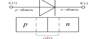
A thyristor
is used as a switching element .
As we said, a thyristor allows you to switch a load that is insensitive to the shape of the supply voltage: an incandescent lamp, a shadow lamp, a halogen lamp, and the like.
You cannot connect an LED driver or an energy-saving CFL type, or any electronic device that has a transformer at the input.
The minimum details of the circuit and the simplicity of the circuit will allow anyone to assemble this circuit, spending no more than 50–100 rubles.
The circuit works as simply as it looks. If you close contact S1, then gradual charging of C1 will begin. During the charging of this capacitor, thyristor VS1 will be open.
Load HL1 will have mains voltage. As soon as the capacitor is charged, thyristor VS1 will close and current will stop passing through it. Our device will shut down and the load will turn off.
The diagram contains the following details:
diode bridge, which performs the function of supplying rectified current to the thyristor: consists of diodes with a maximum current of not less than 1A and having a reverse voltage of not less than 400V (1N4007);
thyristor series BT151 (if you have KU 202N or KU 202M lying around, use it);
- resistance
R1 – 4.3 MOhm, power 1 W; - resistance
R2 200 Ohm, 1W; - R3
of the same power, 1.5 kOhm; - capacitor
C1 is 0.47 µF, 630V or higher voltage; power no more than 200 W; When using incandescent lamps, including halogen lamps, remember that the starting current when turned on can be 10 times higher than the operating current, although this does not last so long. - switch
or toggle switch S1.
Since the whole principle of operation of this relay comes down to charging the capacitor, changing the capacitance of the capacitor
The easiest way is to change
the relay switching time
.
Due to the simplicity of this device, it is impossible to give a simple formula for calculating the holding time, since the time depends on the parameters of a particular thyristor, resistor resistance, and capacitance of the capacitor.
Delay time relay with time adjustment 220 V
To make a more reliable, high-quality and safe device, more effort and money will be required.
Next we will talk about just such a device. There is another article on our website about how to make a time relay on a 555 timer with your own hands with a simpler circuit design, without a transformer. There you can also find a description of the operation of the 555 chip.
The circuit below is based on the 555 timer chip, first released in 1972, but nevertheless not losing its popularity. The use of a microcircuit allows you to count with a high degree of accuracy the required time interval of the timer from 3 seconds to 10 minutes.
A transformer is used to power the device - the control part of the circuit is galvanically isolated.
The load is switched using a power triac. Its activation is carried out by a triac optocoupler having a zero detection circuit.
As a result, load switching occurs close to the moment the sinusoidal supply voltage passes through zero. This switching on is as painless as possible for the load and does not cause interference at the moment of switching on.
Idea 1. On diodes
Let's consider a version of the simplest logical element for operation in a 220V circuit.
Rice. 4. 220V time relay circuit
Here, switching on occurs when button S1 is pressed, after which voltage is supplied to the diode bridge. From the bridge, the potential passes to a timing element consisting of resistors and a capacitor. During the process of accumulating charge, the thyristor VS1 will open and current will flow through the lighting lamp L1. When the capacitor is fully charged, the thyristor will go into the closed state, after which the relay will operate and the lamp will stop burning.
The maximum shutter speed here can be set to several tens of seconds, since its value will be set by the resistor resistance and capacitance. A significant drawback is that this scheme poses a threat to human life in case of electric shock. Therefore, next we will consider an example of manufacturing a 12V time relay.
What are timers, pause relays, delays
Let’s make a reservation right away: homemade auto-timers adjust the delay from a few seconds to 10–15 minutes. There are schemes only for incl. and for on/off load, as well as for activation at certain times of the day. But their delay range and options are limited; there is no function of periodically operating independently several times and adjusting the intervals between such cycles, like in factory outlet devices. However, the homemade capabilities (there are also ready-made similar simple modules on sale) are enough to activate garage ventilation, lighting in the pantry and similar not too demanding operations.
A temporary relay (timer, pause, delay relay) is an automatic release that is triggered at the moment set by the user, turning on/off (closing/opening contacts) of an electrical appliance. The timer is extremely practical in situations where the user needs the device to be activated or deactivated while he is in another location. Also, such a unit will help out in ordinary everyday situations, for example, it will protect you when you forget to turn off/on the equipment.
Thus, the temporary relay will eliminate situations where you left an electrical appliance on, forgot to turn it off, and, accordingly, it burned out or, even worse, caused a fire. By turning on the timer, you can go about your business without worrying about having to return at a certain time to service the equipment. The system is automated, the unit itself will turn off when the set period on the release has expired.
Where is it used?
Many people are familiar with the clicking sounds in Soviet washing machines, when large graduated selectors set a certain delay before turning on/off. This is a vivid example of this device: for example, they set it to work for 10–15 minutes, the drum spun for this time, then, when the clock inside reached zero, the washing machine turned itself off.
Manufacturers always install temporary relays in microwave ovens, electric ovens, electric water heaters, and automatic watering systems. At the same time, many devices do not have it, for example, lighting, ventilation (hood), then you can buy an additional timer. In its simplest form, it looks like a small rectangular block with time selectors and a plug for a regular socket (“daily” timer sockets) into which it is inserted. Then the power cable plug of the device being serviced is inserted into it, and the delay time is adjusted using the controls on the body. There are also standard sizes for placement by connecting to a line (with wires, wiring, for switchboards), for integration inside devices.
Device, types, features
Mostly timers in factory electrical appliances with trip units are based on a microcontroller, which often also controls all operating modes of the automated device where they are installed. The described combination of functions is cheaper for the manufacturer, since there is no need to manufacture separate microcircuits.
We will describe the simplest time delay relay circuits, only with an on/off option. and selecting a time pause in a small range (up to 15–20 minutes):
- for low-voltage power supply (5–14 V) - on transistors;
- on diodes - for power supply directly from a 220 Volt network;
- on microcircuits (NE555, TL431).
There are special factory modules, they can be bought on online sites (Aliexpress, similar and specialized resources), on radio markets, in special stores. Completely handicraft products are created according to similar schemes, mainly for simple tasks: elementary disengagement/coupling of contacts at a certain, specified point in time, while the delay range is small from seconds to 15–20 minutes.
Basic options
- Electronic digital. The RVs of this system are the most modern and accurate. They operate a generator, the frequency of which is stabilized by a special device. The most widely used crystal for this purpose is quartz crystal. Most likely, the reader has already come across the name “quartz oscillator”. It produces voltage at a constant frequency and is insensitive to changes in ambient temperature. The signal generated by the generator is used to generate stable pulses. They are counted by special microcircuits. Based on this, a signal is generated that controls the PB switch. In this way, you can most accurately form a time interval of any duration.
Electronic model of RV
- Electronic analog. Based on the so-called RC circuit time constant. It is determined by the fact that to fully charge (discharge) a capacitor through a resistor, the greater the resistance of the resistor, the longer it takes. Using this principle, it is possible to create quite accurate and simple in design RVs. Their time intervals will be within a few seconds.
- Electromagnetic or induction. These are two definitions of the same operating principle. It is based on the fact that the electromagnetic field cannot appear and disappear instantly. Depending on the inductance value of the element and the special design of the cores, a transient process lasting from hundredths to several seconds is obtained. A time-tested system that is still used in special radios.
Electromagnetic RF
- Pneumatic mechanism. It has long been used in industrial equipment. It solves well the problem of synchronous operation of a large number of actuators. The system is easily and clearly adjusted by changing the diameter of the hole for air movement. The larger its dimensions, the faster the air flow will fill the working volume (for example, a cylinder with a piston) of this pneumatic mechanism and, accordingly, the shorter the response time of such an RV. And vice versa. The time interval for such relays is within a few minutes.
Pneumatic RV
- Clockwork. It is also called anchor. This is the most common of all time interval generator options. It is based on the deformation of the spring. It is strained when the mechanism is started, and the elastic force of return to its original state, slowed down by gears and flywheels, provides one or another time interval. Finally, the spring force moves the actuator contact, which either directly breaks the electrical circuit or controls the relay. Based on the operation of the washing machine, you can judge what time can be set for such an RW.
Anchor RV
- Electromechanical design. Powered by a multi-pole synchronous motor. The rotation speed of this motor depends only on the frequency of the supply voltage. If it is provided by a 220 V industrial network, the frequency is very stable. The key to this stability is the mass of generator rotors in power plants. You can create a time interval of several hours. They are used industrially mainly in relay protection circuits. You can set any time interval as long as there are no power failures.
Electromechanical RV
How does the 555 chip work?
Before moving on to the example of a relay device, let's consider the structure of the microcircuit. All further descriptions will be made for the NE555 series chip manufactured by Texas Instruments.
As can be seen from the figure, the basis is an RS flip-flop with an inverse output, controlled by outputs from comparators. The positive input of the upper comparator is called THRESHOLD, the negative input of the lower one is called TRIGGER. Other comparator inputs are connected to a supply voltage divider consisting of three 5 kOhm resistors.
As you most likely know, an RS flip-flop can be in a steady state (it has a memory effect of 1 bit) either in a logical “0” or in a logical “1”. How it works:
- The arrival of a positive pulse at input R (RESET) sets the output to logical “1” (namely “1”, not “0”, since the trigger is inverse - this is indicated by the circle at the trigger output);
- The arrival of a positive pulse at input S (SET) sets the output to logical “0”.
Three 5 kOhm resistors divide the supply voltage by 3, which leads to the fact that the reference voltage of the upper comparator (the “–” input of the comparator, also known as the CONTROL VOLTAGE input of the microcircuit) is 2/3 Vcc. The reference voltage of the lower one is 1/3 Vcc.
With this in mind, it is possible to create tables of states of the microcircuit regarding the TRIGGER, THRESHOLD inputs and OUT output
Note that the OUT output is the inverted signal from the RS flip-flop
| TRIGGER < 1/3 Vcc | OUT = log "1" | undefined state OUT |
| TRIGGER > 1/3 Vcc | OUT remains unchanged | OUT = log "0" |
In our case, to create a time relay, the following trick is used: the TRIGGER and THRESHOLD inputs are combined together and a signal is supplied to them from the RC chain. The state table in this case will look like this:
| THRESHOLD, TRIGGER < 1/3 Vcc | OUT = log "1" |
| 1/3 Vcc < THRESHOLD, TRIGGER < 2/3 Vcc | OUT remains unchanged |
| THRESHOLD, TRIGGER > 2/3 Vcc | OUT = log "0" |
The NE555 connection diagram for this case is as follows:
After power is applied, the capacitor begins to charge, which leads to a gradual increase in the voltage across the capacitor from 0V onwards. In turn, the voltage at the TRIGGER and THRESHOLD inputs will, on the contrary, decrease, starting from Vcc+. As can be seen from the state table, there is a logical “0” at the OUT output after Vcc+ is applied, and the OUT output switches to a logical “1” when the voltage at the indicated TRIGGER and THRESHOLD inputs drops below 1/3 Vcc.
The important fact is that the relay delay time, that is, the time interval between applying power and charging the capacitor until the OUT output switches to logic “1,” can be calculated using a very simple formula:
T = 1.1 * R * C And as you can see, this time does not depend on the supply voltage. Consequently, when designing a time relay circuit, you don’t have to worry about power stability, which significantly simplifies the circuit design.
Next, we present a drawing of a variant of the microcircuit in a DIP package and show the location of the chip pins:
It is also worth mentioning that in addition to the 555 series, the 556 series is produced in a package with 14 pins. The 556 series contains two 555 timers.
How to make a relay with a switch-off delay
The above circuit, thanks to the features of the NE555, can be easily converted into a shutdown delay timer. To do this, you need to swap C4 and R2-VD4. In this case, K1 will close the load HL1 immediately after turning on the device. The load will be turned off after the voltage on capacitor C4 increases to 2/3 of the supply voltage, that is, to approximately 8 V.
The disadvantage of this modification is the fact that after disconnecting the load, the circuit will remain exposed to dangerous voltage. This drawback can be eliminated by connecting a relay contact to the power supply circuit to the timer in parallel with the power button ( namely a button, not a switch! ).
The diagram of such a device, taking into account all the modifications, is shown below:
Attention! In order for dangerous voltage to actually be removed from the circuit by the relay contact, it is necessary that the PHASE be connected exactly as shown in the diagram.
Please note that the 555 timer is used and described on our website in another article, which discusses a time relay circuit with a 220V turn-off delay. The circuit presented there is more reliable, contains galvanic isolation and allows you to change the time delay interval using a regulator.
If you need a printed circuit board drawing when making a product, write about it in the comments.
Delay turning off and turning on the relay using a capacitor and 12V resistor
It is not necessary to resort to using integral timers like the NE555 if you only need a delay before start/stop. Using a capacitor paired with a resistor and transistor will solve the problem without complex ICs. Use the diagram below
This is a classic circuit using a capacitor, resistor, diode and bipolar transistor. The circuit uses an NPN type transistor. It works like this: after applying voltage to resistor N resistance, capacitor N capacitor begins to charge. When the bias voltage is reached, the diodes open, and then the control emitter pn junction of the transistor opens, which “opens” the transistor and the current begins to flow in the collector-emitter direction.
Our semiconductor operates in active mode. Until the current controlling the base leaves this mode, the gain will not take on a descending form. This continues until the current value completely crosses the cutoff threshold - the collector-emitter junction closes. When turned on, the opposite happens.
For assembly, it is recommended to use a KT827 transistor with an npn junction. The diode is suitable KD105B or similar in parameters. The capacitor and resistor are selected individually in each case, more on this below.
Operating principle
Table of degrees of protection
The main function of the RF is the formation of a time delay for switching control groups of contacts. The implementation of the delay depends on the design features of the device. There are many varieties of RV. From a functional point of view, they are pneumatic, motor, electromagnetic, electronic, as well as clockwork devices. They differ in parameters, appearance and installation method, and have the following technical characteristics:
- maximum switching current;
- rated switching voltage;
- type of contacts, their number;
- wear resistance (estimated number of inclusions);
- IP protection degree.
Devices are divided into devices with a switch-off or switch-on delay. Many relays have two options at once, changing the type of switching. The operating algorithm is as follows:
- During startup, the contact group is activated - the contacts are closed for the relay with a turn-off delay.
- The time delay mechanism is cocked.
- After the programmed interval has expired, the contact group changes order.
The on-delay relay works in a similar way. In cyclic type devices, a given sequence is repeated many times.
Video description
Mechanical timer for turning on and off the lighting in the aquarium.
In the first case, problems may arise if there is a power failure. However, such timers can work for a very long time without requiring special attention. Devices that use a battery have a significant degree of autonomy, but operate for a limited time until the charge runs out.
Programmable timer for controlling household appliances Source 220.guru
For each such device, in practice, a certain operating mode is established. It is important that the one that the owner needs is provided for this device. The most common are the following:
- A universal timer allows you to plan work algorithms within a wide range.
- Random switching may be used.
- Countdown time is applied.
- An astronomical countdown is underway.
- Using weekly rhythms. For example, if you need to regularly perform actions on certain days of the week.
- Actions based on circadian rhythms.
Where and how it is used
220V time delay relays are common in the areas of electrical power distribution and generation. The protection they provide to high-voltage lines creates trouble-free operation of substations, as well as other equipment.
Protection control elements are manufactured for connection switching at very high operating voltages (several thousand Volts).
Thanks to the installation of relay protection, it is possible to back up power lines, as well as instantly disconnect damaged or dangerous sections of power networks.
Electromagnetic type devices are widely used in various types of household appliances, such as washing machines, refrigerators, etc.
Today, time relays of this type are widely used in control systems for production and conveyor lines. Such control systems are usually used in industries with high parasitic potentials, at which control of semiconductor systems becomes impossible.
Advantages of a time relay
Time relay saves energy
Analogue and digital time relays are very convenient for controlling executive circuits of various household and industrial devices.
The on and off relay has a number of positive factors:
- optimizes the operation of household electrical and pumping appliances;
- saving energy resources when connecting a smart home system;
- switching of production equipment, mechanisms and other devices;
- settings allow you to select a mode that is convenient for an individual user;
- it is possible to set cyclic shutdown and on;
- A sound signal notifies you when the device is triggered.
In everyday life, a timer is used to operate a fan, refrigerator, air conditioner, and optimize lighting. The device can be used in educational organizations, workshops and schools, for example, to make a bell. Farms install special artificial light for the growth and development of animals. In production, various machines and mechanisms are switched on and off using relays. In agriculture, the relay controls irrigation and watering systems, pumping stations and ventilation units.
What is a time relay?
We must assume that the reader of this article is not an expert in electrical engineering, but only an inquisitive user trying to broaden his horizons and apply the information received in everyday life. Therefore, to begin with, it will be useful to remember what is hidden under the general term “relay”?
We will not give a long “scientific” formulation of this concept - it may not be entirely clear to a beginner. In simple terms, a relay is an electromechanical or electronic device that switches (connects or breaks) an electrical circuit when it receives an external control signal. More precisely, operation occurs when the external influence reaches a certain specified value.
The first relays were invented, manufactured and used in the middle of the 19th century - they became an indispensable component of telegraph communications devices that were rapidly developing in those days. Since then, of course, these devices have gone through a long path of modifications and improvements, their reliability has increased, and new types have appeared that can operate in a wide variety of operating conditions. But the principle remains unchanged - an external control action controls the closing, opening or switching of electrical circuits.
The diagram very clearly shows the basic principle of operation of an electromechanical relay. Well, the number of contacts and their switching pattern when the device is triggered is far from limited to these two examples.
For the most part, relays are controlled by electrical signals - when the current or voltage reaches a certain value. But, by the way, the control action is not necessarily electrical. There are relays whose operation is caused by changes in pressure in the pipeline, ambient temperature, object illumination, and others. All this opens up very wide possibilities for automation and ensuring the safe operation of various electrical equipment.
Pressure switch - in domestic conditions it is usually installed in the power supply circuit of pumping equipment, which allows you to automate the operation of autonomous water supply or heating systems.
It can be added that in our time, along with electromechanical relays, “solid-state” electronic switches are increasingly being used, in which contact switching occurs through the use of cascades of semiconductor elements or integrated circuits.
Now - to the question of what a time relay is.
And the clue is in the name itself. This is, in principle, the same relay, but the operation of which occurs with a certain delay after the application (or removal) of the control signal. Or switching of circuits is carried out with a certain time algorithm.
Such devices have found very wide application in the automation of industrial equipment. But they are widely used in domestic conditions. For example, some of the worries about managing lighting devices, climate control equipment or ventilation systems can be transferred to them, resulting in a very impressive energy saving effect. It becomes possible to perform the necessary actions with household electrical appliances at a given time, even in the absence of the owners or without their intervention. In a word, time relays can greatly simplify the life of home owners.
Electromechanical analog time relay in a housing for installation on a standard DIN rail. Even outwardly, some devices for this purpose resemble ordinary watches.
This was, so to speak, general information. Now let's move on to a closer look at the variety of these devices and the algorithms for their operation.
What are they used for?
The use of time relays is common in domestic conditions. For example, when operating an air conditioner, actions may be required that are carried out cyclically at certain intervals. For example, cooling or heating (depending on weather conditions), which are performed with an hour break.
The switch will help you warm up your food before dinner. If the owner leaves the house for some time during the cold season, it is better for him to turn off the heating. But if he only does this for a couple of days, he can arrange for it to be turned on periodically with minimal parameters.
Socket type timer Source sovet-ingenera.com
Operating principle of protective devices
To protect against electrical impulses caused by lightning, a lightning arrester is installed together with an SPD. And you can protect the line from the flow of electrons, the parameters of which do not correspond to the operating characteristics of the network, using special sensors, as well as overvoltage relays.
It should be said that both the DPN and the relay differ in principle of operation and purpose from the stabilizer.
The task of these elements is to stop the supply of electricity if the value of the difference exceeds the maximum threshold specified in the technical data sheet of the protective device or set by the regulator.
After normalizing the parameters of the electrical line, the relay switches on automatically. DPS for line protection should be installed only in conjunction with a residual current device. Its task is to cause a current leak when a malfunction is detected, under the influence of which the RCD will trip.
Visually about the voltage relay in the video:
The disadvantage of this circuit is that it needs to be turned on manually after the voltage returns to normal. In this regard, a voltage stabilizer compares favorably. This device provides an adjustable time delay for current delivery if it is triggered by excessive voltage. The stabilizer is often used to connect air conditioners and refrigeration units.
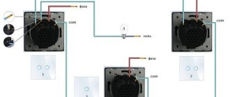
Scheme for 220 Volts
Timers on transistors and microcircuits operate from 5–14 V (standard from 12 V). 220 Volt time relays are diode assemblies with magnetic starters. If the equipment being serviced is low-power (for example, lighting, lamps, soldering irons, boilers, small motors, etc.), then the latter need not be installed - the diode bridge and thyristor transform the voltage themselves.
Let's look at the light bulb timer, the main parts: diode bridge, thyristor. It is not recommended to connect any other load: the thyristor will only pass a positive sinusoid of 220 Volt variables. This is enough for the listed consumers, but other electrical appliances may not be able to withstand it.
What you will need:
- resistors: 4.3 mOhm (R1), 200 Ohm (R2) and adjustable 1.5 kOhm (R3);
- 4 diodes with max. current from 1 A, reverse voltage from 400 V;
- capacitor 0.47 µF;
- thyristor (analogs are possible) BT151;
- regular microswitch.
The principle is standard for such assemblies: gradual charging of the AC. C1 (starts after activation of S1). Thyristor VS1 is open, and load L1 receives 220V from the network. After charging, it closes, cutting off the current - the lamp turns off. The pause is regulated by setting the value to R3 and selecting capacitance C1.
The assembly has a disadvantage: touching any exposed wiring or leg can result in a strong electric shock, since the elements receive a strong current.
What is a time relay?
We must assume that the reader of this article is not an expert in electrical engineering, but only an inquisitive user trying to broaden his horizons and apply the information received in everyday life. Therefore, to begin with, it will be useful to remember what is hidden under the general term “relay”?
We will not give a long “scientific” formulation of this concept - it may not be entirely clear to a beginner. In simple terms, a relay is an electromechanical or electronic device that switches (connects or breaks) an electrical circuit when it receives an external control signal. More precisely, operation occurs when the external influence reaches a certain specified value.
The first relays were invented, manufactured and used in the middle of the 19th century - they became an indispensable component of telegraph communications devices that were rapidly developing in those days. Since then, of course, these devices have gone through a long path of modifications and improvements, their reliability has increased, and new types have appeared that can operate in a wide variety of operating conditions. But the principle remains unchanged - an external control action controls the closing, opening or switching of electrical circuits.
The diagram very clearly shows the basic principle of operation of an electromechanical relay. Well, the number of contacts and their switching pattern when the device is triggered is far from limited to these two examples.
For the most part, relays are controlled by electrical signals - when the current or voltage reaches a certain value. But, by the way, the control action is not necessarily electrical. There are relays whose operation is caused by changes in pressure in the pipeline, ambient temperature, object illumination, and others. All this opens up very wide possibilities for automation and ensuring the safe operation of various electrical equipment.
Pressure switch - in domestic conditions it is usually installed in the power supply circuit of pumping equipment, which allows you to automate the operation of autonomous water supply or heating systems.
It can be added that in our time, along with electromechanical relays, “solid-state” electronic switches are increasingly being used, in which contact switching occurs through the use of cascades of semiconductor elements or integrated circuits.
Now - to the question of what a time relay is.
And the clue is in the name itself. This is, in principle, the same relay, but the operation of which occurs with a certain delay after the application (or removal) of the control signal. Or switching of circuits is carried out with a certain time algorithm.
Such devices have found very wide application in the automation of industrial equipment. But they are widely used in domestic conditions. For example, some of the worries about managing lighting devices, climate control equipment or ventilation systems can be transferred to them, resulting in a very impressive energy saving effect. It becomes possible to perform the necessary actions with household electrical appliances at a given time, even in the absence of the owners or without their intervention. In a word, time relays can greatly simplify the life of home owners.
Electromechanical analog time relay in a housing for installation on a standard DIN rail. Even outwardly, some devices for this purpose resemble ordinary watches.
This was, so to speak, general information. Now let's move on to a closer look at the variety of these devices and the algorithms for their operation.
This is interesting: The principle of operation of pressure, flow and level sensors: we explain in detail
Characteristics of installations
The characteristics determine the possibility of using devices in certain operating conditions. The properties of time delay settings have four directions:
- Delay time range. It can be adjusted within wide limits.
- Work stability. This parameter applies to electronic devices and characterizes the device’s ability to function when the supply voltage changes.
- Durability measured in on-off cycles.
- Electronic devices are characterized by their power consumption.
Each timer is characterized by certain parameters. The operating algorithm is important, namely the sequence of switching on and off.
Most commonly used algorithms:
- Turn-on delay - after power is applied to the timer, the output pulse is generated after the set time has counted down.
- The pulse is generated when turned on - the signal appears when the timer's power supply is turned on and disappears after the set time has expired.
- After turning on the power supply to the timer, the output signal appears at the moment the control signal is removed and disappears after a set time.
- Delayed shutdown after power failure - the output signal appears when the timer is powered on and disappears after a set time after the power is turned off.
- Cyclic mode - after turning on the power supply to the timer, the pulse time alternates with the pause time and so on until the power supply is turned off.
In order to connect the timer, you need to know in which network it will be mounted - single-phase or three-phase . It is important to consider what this timer will switch, what load needs to be turned off or on. Using this data, you can select a device with the required characteristics.
Main characteristics of the device
In specialized retail outlets there are delay devices with different characteristics, produced by different manufacturers. The quality of products from renowned manufacturers is confirmed by certificates and the service life they guarantee. Popular companies include: Hager, Asko, Eaton, ABB, Schneider, Novatek. Regardless of the type and model, time relays are characterized by the following parameters:
Connecting the device usually does not cause problems. The device is connected to a break in the line suitable for the load. Each relay must come with instructions from the manufacturer with a detailed connection diagram and description. Moreover, it can also be depicted on the device body itself.
Types of time relays
So, the main task of a 12V time relay is to delay from the initial signal to the final one. So this very delay can be formed in several ways. Hence the different types:
- Mechanical.
- Electromechanical.
- Electronic.
- With damping devices.
The latter include a pneumatic subtype, which includes pneumatic attachments and an electromagnetic drive. By the way, assembling it with your own hands is as easy as shelling pears. But all this is already a thing of the past, except for electronic analogues.