Differential relays D-4V and RDZ-504
Purpose and technical data. Differential relays are used to protect against short-circuit currents in the power circuits of traction motors and auxiliary machines of an electric locomotive in traction mode.
The relay blocking contacts protecting the power circuit of the traction motors are included in the holding coil circuit of the high-speed switch BVP-5; The relay blocking contacts protecting the power circuit of auxiliary machines are included in the coil circuit of the high-speed switch BVE-< TsNII. On electric locomotives VLYU up to No. 1587 built by TEVZ, differential relays D-4V are installed, and starting from No. 1587, relays RDZ-504 are installed in the power circuit of traction motors instead. The technical data of the relay is as follows:
d-4v rdz-504
Rated voltage of the power circuit, A 3000 3000
Rated voltage of the switching coil and contacts, V…… 50 50
Magnetomotive force (setpoint), A, at rated voltage on a coil with an additional resistor of 300 Ohm resistance………. 100 100-ao
Own response time (at a current rise rate of over 105 A/s), s, no more……… 0.0065 0.0065
Coil resistance at a temperature of 20° C, Ohm………6.7-7.5 3.6
The longest duration of activation of the coil without an additional resistor at a voltage of 55 V, s……. 60 40
Rated current of contacts, A. . 5 5
Number of normally open contacts…. eleven
Contact failure, mm……2-3 1.5-2
Contact gap, mm...... - 4-5
Working gap at the center of the pole with the armature open, mm......10-12 5±0.5
Area of contact of the armature to the core of the magnetic circuit, %...... - 80
The coil must ensure restoration of the relay by forcing at a current, A, no more than 4.4
AC voltage frequency
50 Hz to test the insulation of the coil against the blocking or the nearest mounting bolt for 1 min, V. 1500 1500 Weight, kg………. 17 6
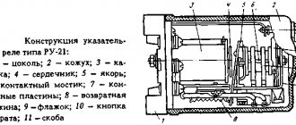
Design and principle of operation. Differential relay D-4V (Fig. 128) consists of a laminated magnetic circuit 8 (fastened by two side brackets), a coil 6, an additional resistor 7, an armature 5 and blocking contacts 4. In the upper part of the magnetic circuit, an insulating panel 1 is fixed to the protrusions of the side brackets. A coil is placed on one of the protruding magnetic core packages, and an armature with an adjusting spring 2 and a locking contact is installed on the other. A stand with a limiting strip 3 is attached to the middle of the insulating panel. A magnetic shunt package made of electrical steel is fixed between the brackets. An additional resistor, blocking contacts and output clamps are attached to the insulating panel. The cables of the beginning and end of the circuit protected by the differential relay are passed through the window of the magnetic circuit.
The relay turns on when a voltage of 50 V is applied to the coils, after which a resistor is introduced into its circuit. The direction of the magnetic flux generated by the coil is shown in Fig. 129 is a solid line, and the magnetic flux arising from the passage of the unbalance current of power cables stretched through the window of the magnetic system is dashed. In the working gap a, the indicated flows are directed counter.
In the absence of a short circuit (short circuit) in the area protected by the differential relay, the magnetic flux created by the currents flowing through the power cables is zero. Under the influence of the magnetic flux of the coil, the armature is attracted and the blocking contacts are closed.
When does short circuit occur? an unbalance current occurs in the circuit protected by the differential relay. When the unbalance current reaches a value equal to the relay setting current, the magnetic flux becomes such that the force from the resulting flux in the working gap area becomes less than the force of the adjusting spring, and the relay armature disappears. In this case, the blocking contacts open and break the power supply circuit of the holding coil of the BVP-5 or BVE-TsNII switch. The latter turn off and break the short-circuit current.
The magnetic shunt serves to ensure that during a short circuit. there was no reverse switching of the armature, since the short-circuit current does not stop immediately. When the armature falls off, the short-circuit current continues for some time. flows through the power cables, and the magnetic flux from this current tends to attract the armature again. In the presence of a magnetic shunt, the flux from the unbalance current will mainly flow through it, since the conductivity of this section of the magnetic circuit AB is much greater than the conductivity of the air gap a - 10 ~ -12 mm. The diagram for connecting the relay to the power circuit is shown in Fig. 130.
Relay D-4V of the power circuit of traction motors is adjusted to an unbalance current of 100 A with one wire inserted into the frame. Relay D-4V of the power circuit of auxiliary machines is regulated for an unbalance current of no more than 50 L with two turns of wire inserted into the frame.
At the stand, the relay is adjusted as follows. A wire is inserted into the magnetic circuit frame, and voltage is applied to the coil. The armature must be attracted at a voltage across the coil (without an additional resistor) of 50 V and reliably held at 40 V when an additional resistor installed on the relay is connected to the coil circuit. A current equal to the unbalance current is passed through the wire inserted into the frame. Since the relay is polarized, during testing and installation the specified connection polarity should be strictly adhered to. The armature should fall off when the unbalance current is adjusted by the relay, and the voltage on the coil is 50 V with the additional resistor turned on. The relay setting current is adjusted by changing the spring tension. If the relay armature does not fall off when current passes through the wire, you need to change the polarity of the relay coil.
Checking the relay adjustment on an electric locomotive is performed as follows. The differential relay of the main circuit is adjusted to an unbalance current of no more than 100 A. Before testing, it is necessary to make sure that opening the relay contacts manually causes the high-speed switch BVP-5 to turn off. For testing, it is necessary to artificially create a short circuit. in front of the traction motor, for which a jumper is placed between the engine switch blade and the ground.
To check the polarity of the relay when the BVP-5 switch is on and the electric locomotive is braked, install the main handle of the controller in the 1st, 2nd and 3rd positions. If the relay blocking does not open and the BVP-5 switch does not turn off, then change the polarity of the relay switch. The relay setting is checked with the BVP-5 switch on and the braked electric locomotive in the 1st position. If the relay contacts do not open and the BVP-5 does not turn off, then increase the tension of the relay adjusting spring.
Differential relays of auxiliary circuits regulate the unbalance current to no more than 50 A. Before testing, it is necessary to make sure that opening the relay contacts manually causes the high-speed switch BVE-TsNII to turn off. For testing, a short circuit is created. after the fan on the fan switch or in the starting resistor of the second fan at terminal P68 (see tab, Fig. 188). Then the pantograph is raised and the fans are turned on at low speed. The relay's latching contacts open and the switch turns off. If this does not happen, then check the polarity of the relay or increase the spring tension. The spring tension, measured along the axis of the core, must be at least 6.5 kgf. When putting an electric locomotive into operation, technical maintenance of TO-3 and routine repairs, check the correctness of switching on and adjusting the relay for unbalance current; restoring the relay by forcing it at a voltage of 35 V in the control circuit,
Differential relay RDZ-504 (Fig. 131, 132) consists of a laminated magnetic circuit 8, a coil 5, an armature 4, an adjusting spring 6, a blocking 2 and an additional resistor consisting of two parallel-connected resistors 7 of type PEV-15-390 Ohm. The magnetic core, blocking and additional resistor are installed on panel 1. The relay is covered with casing 3.
The operating principle, adjustment and adjustment check of the differential protection relay RDZ-504 are similar to the D-4V relay.
After checking the relay setting on an electric locomotive, the tension of the adjusting spring, measured along the axis of the magnetic core, should be less than 7 kgf, and the force reserve in the pulled position of the armature and a voltage of 40 V should be at least 0.5 kgf.
⇐ | Boxing sensor DB-018 | | Electric locomotive VL10 | | Speed relay RKO-28 | ⇒
Residual current device - differential relay
In general, a differential relay is a device that controls the current in both the phase and neutral conductors. Under normal conditions, the current in the phase and neutral conductors should be the same. If the current in the phase conductor differs from the current in the neutral conductor, the differential relay will immediately break the circuit in an instant. Why is this being done? The fact is that the difference in currents in the conductors occurs in an abnormal situation. If the current in these conductors is different, this means that part of the current flows somewhere. This part is called leakage current. Current leakage occurs if the insulation of conductors is broken, or unauthorized contact occurs with live parts of the conductor, which means that a person may be electrocuted.
A current greater than 30 mA is considered life-threatening. Therefore, differential relays open the circuit if the leakage current reaches 30 mA. But such a differential relay protects against electric shock due to indirect contact. A differential relay with a rated leakage current of 10 mA protects against electric shock from both indirect contact and direct unintentional contact with live parts. These relays, with rated leakage currents of 10 and 30 mA, are used in group electrical networks. Such relays, despite their considerable cost, should not be installed alone to protect the entire apartment, because if there is a leak in one of the groups, the entire apartment will turn off, and this is not very convenient. In addition, it will not be clear where the leak is occurring. Therefore, such relays must be installed on each of the groups. To protect the entire electrical installation, the industry produces relays with a rated leakage current of 300 mA. Such relays are usually four-pin and designed for use in three-phase electrical networks.
Thus, differential relays are used exclusively for protection against electric shock.
third option
Residual current device (abbr. RCD ; more precise name: residual current device controlled by differential (residual) current
, abbr.
RCD-D ) or differential current switch ( VDT ) or protective circuit-breaker device ( ZOU ) is a mechanical switching device or a set of elements that, when the differential current reaches (exceeds) a given value under certain operating conditions, should cause the contacts to open.
May consist of various individual elements designed to detect, measure (compare with a given value) differential current and close and open an electrical circuit (disconnector) [1]. The main task of an RCD is to protect people from electric shock and from fire caused by current leakage through worn wire insulation and poor-quality connections.
Combined devices that combine an RCD and an overcurrent protection device are also widely used; such devices are called RCD-D with built-in overcurrent protection, or simply a diffautomatic device . Often differential automatic devices are equipped with a special indication that allows you to determine for what reason the operation occurred (from overcurrent or differential current).
Goals and operating principles
RCD diagram and operating principle
The operating principle of an RCD is based on measuring the balance of currents between the current-carrying conductors included in it using a differential current transformer. If the current balance is disturbed, the RCD immediately opens all contact groups included in it, thus disconnecting the faulty load.
RCD measures the algebraic sum of currents [ source not specified 1180 days
] flowing through the controlled conductors (two for a single-phase RCD, four for a three-phase, etc.): in the normal state, the current “flowing” through one conductors must be equal to the current “flowing out” through the others, that is, the sum of the currents passing through the RCD is zero (more precisely, the amount should not exceed the permissible value). If the amount exceeds the permissible value, then this means that part of the current passes in addition to the RCD, that is, the controlled electrical circuit is faulty - there is a leak in it.
Conditions for triggering the RCD:
· Direct human contact with live parts and contact with the “ground”.
· Damage to the main insulation and contact of live parts with a grounded body.
· Replacement of neutral and grounding conductors.
· Replacement of phase and neutral conductors and human contact with live parts and its simultaneous contact with the “ground”.
· Breakage of the neutral conductor before (and after the RCD) and a person touching live or live parts and simultaneously making contact with the “ground”.