4 / 5 ( 3 voices)
A voltage relay is necessary to protect the electrical network from voltage surges. Currently, the issue of stable voltage in the electrical network is quite acute.
Instagram https://instagram.com/elektroschyt VKontakte https://vk.com/elektrika46
Network organizations are in no hurry to reconstruct and modernize power lines, substations and transformers. Meanwhile, the situation is only getting worse, so voltage fluctuations in our networks are quite common.
For those who still doubt the installation of a relay to protect their home or believe in the quality of construction and installation work in modern new buildings. Below is a screenshot of one of the latest comments, where the author writes that he had a “zero burnt out” in his new building.
According to GOST 29322-92, the voltage in the electrical network of our country should be within 230 V in one phase and 400 V between phases. But if you live in a rural area or near a city, then problems with constant voltage levels are very high, and in the city itself this cannot be ruled out, especially in older housing stock. Voltage surges have a very detrimental effect on electrical appliances in the house. For example, due to low voltage, a refrigerator or air conditioner may burn out (the compressor will not start and overheat), the power of the microwave is greatly reduced, and incandescent lamps glow dimly. Well, high voltage will simply “kill” your household appliances. I am sure that many have heard about “zero burnout” in high-rise buildings, and how entire hallways are taken to workshops to repair household appliances.
The reasons for voltage fluctuations in the network are different:
- Shorting one of the phases to neutral, the result will be 380 Volts in the outlet.
- Burnout (break) of zero, if you have a low load at this time, then the voltage will also tend to 380 V.
- Uneven distribution of load across phases (misalignment), as a result, the voltage decreases in the most loaded phase, and if a refrigerator and air conditioners are connected to it, there is a high probability that they will “burn out.”
Example video showing the operation of a voltage relay
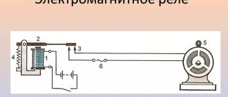
Special devices - voltage control relays - help solve the problem of voltage surges in networks. The principle of operation of such relays is quite simple, there is an “electronic unit” that monitors that the voltage is within the limits specified by the settings and if there are deviations, it signals the release (power section), which turns off the network. All household voltage control relays turn on automatically after a certain time. For ordinary consumers, a delay of a few seconds is sufficient, but for refrigerators and air conditioners with compressors a delay of several minutes is needed.
Here is the link for a detailed article about the RN-260t voltage relay from Novatek-Electro.
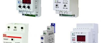
Voltage control relays are available in single-phase and three-phase types. Single-phase voltage relays disconnect one phase, while three-phase voltage relays disconnect all three phases at the same time. When using a three-phase connection at home, single-phase voltage relays should be used so that voltage fluctuations on one phase do not lead to the shutdown of other phases. Three-phase ones are used to protect motors and other three-phase consumers.
I divide surge protection devices into three types: UZM-51M from Meander, Zubr from Electronics and all the others. I am not imposing anything on anyone - this is my personal opinion.
Voltage relay Zubr (Rbuz)
This device is designed to protect against voltage surges (zero burnout). BISON is produced in Donetsk.
I will note the features of this voltage relay.
Voltage indication on the device – shows the voltage value in real time. This is quite convenient and necessary for assessing the voltage situation in the network. The reading error is low, the difference relative to the Fluke 87 high-precision multimeter is only 1-2 Volts.
Zubr voltage relays are produced for various rated currents: 25, 32, 40, 50 and 63A. The device, with a rated current of 63A, can withstand a current of 80A for 10 minutes.
The upper voltage value is set from 220 to 280 V in steps of 1 Volt, the lower - from 120 to 210 V. The restart time is from 3 to 600 seconds, in steps of 3 seconds.
I set the Zubr relay, the maximum (upper) voltage value is 250 Volts, and the lower value is 190 Volts.
Devices with the index t in the name, for example Zubr D63 t , have thermal protection against internal overheating. Those. when the temperature of the device itself increases to 80 degrees (for example, due to heating of the contacts), it turns off.
Zubr relays occupy 3 modules or 53 mm on a DIN rail and are only single-phase.
The passport and the Zubr connection diagrams provided do not say about current limitations, but in the old documentation it was previously indicated that no more than 0.75 of the nominal.
User instructions
As promised, I am posting instructions for the voltage relay, which can be seen in the photo.
I tried to write in simple language what it is, why and how:
Voltage control relay
Designed to automatically switch off the load if the voltage value exceeds the permissible limits. They work on each phase separately.
Automatic machines F1, F2, F3 are bypasses; during normal operation they MUST BE OFF (lower position). They are switched on in emergency cases, under the personal responsibility of the switcher!
Attention! When the bypass is turned on, the load is not protected from dangerous voltages!
During normal operation, voltage relays A1, A2, A3 indicate the voltage value in their phase. If the voltage goes beyond the set limits, the relays are turned off and the voltage readings flash. Turning on - approximately 1 minute after the input voltage has normalized.
If you need to change the voltage limits, please refer to the instructions. The bypass circuit breaker must be turned on when setting the voltage limits and delay times .
Thank you all for your attention, questions and comments, as always, I’m waiting for you in the comments.
Zubr voltage relay wiring diagram
Currently, manufacturers claim that the relay can be connected at its nominal value. If the rating of the Bison is less than the rating of the input circuit breaker, then you need to use a voltage relay - a contactor - in the connection diagram.
Technical data sheet Zubr D63t
The manufacturer provides 5-year warranty on the Zubr voltage ! Has very good reviews from fellow forum members. And just like Meander on the MasterCity forum there is a Zubra representative who is not afraid to communicate publicly. And by the way, it is indicative from the example of UZM and Zubr that representatives of manufacturers of quality products are not afraid to communicate on forums.
Input 2
Here I photographed the input machine:
2 – Input automatic switch (switch) to the meter
Three-phase input differs fundamentally from single-phase. More details in my article.
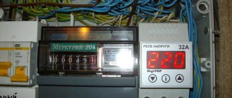
And the electrical panel looked like this:
2 – appearance of the electrical panel
The meter has a magnetic seal. Why it is needed - I refer you to the article about Ways to Steal Electricity. But I say again - you need to live honestly!
2 – Magnetic seal on a three-phase meter
Appearance of the place where there will be a gap for connecting our voltage control relays:
2 – counter outputs
Closer, we are interested in the upper connection to the switch, on the left:
2 – wires between the meter and the switch, where the three-phase voltage relay will be connected
There's still a voltmeter in the way, but you'll have to leave it.
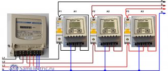
The process of assembling the second panel with three Barrier voltage control relays is shown:
2 – Three-phase voltage control relay based on Barrier relay
This is how this shield is connected:
2 – Connecting the voltage relay to the gap after the meter
This connection is very important because all power to the office goes through it. Therefore, I made it through screw-type terminal blocks (clamps).
The blue wires that previously went to the switch terminals now go through the terminals to the voltage relay panel. And from the Barrier outputs, the wires are connected directly to the switch terminals.
The connections in the panel are shown in the photo:
2 – Connections in the panel of the three-phase voltage control relay
The input cable carries three phases and zero. The current through the neutral wire is more than 100 times less than through the phase wires, so it can be neglected.
The second output cable uses three cores, the fourth is a spare (reserve).
As a result, the currents in the cables are the same, the cable is used at 75%, which is optimal from the point of view of overheating.
The second electrical panel took this form:
2 – Electrical control room with a new panel
A closer look at our shield:
2 – Panel with three-phase voltage control relay
Voltage relay RN-111, RN-111M, RN-113 from Novatek
These voltage relays are manufactured here in Russia. As you can see from the title, Novatek offers three types of voltage relays.
RN-111 and RN-111M are practically the same device in terms of parameters; their main difference is that the RN-111M relay has a voltage indication, while RN-111 does not.
The upper voltage limit is from 230 to 280 V, the lower limit is from 160 to 220 V. The automatic restart time is from 5 to 900 seconds. These relays have a 3 year warranty.
Setting LV response thresholds
The overvoltage protection relay is configured after analyzing the current state of the electrical network and wiring . It is necessary to pay attention to factors such as:
- Voltage at the socket. It is 220 V only on the pages of textbooks. The actual voltage in the network can be in the range of 190-240 V. It makes no sense to configure the LV to turn off when it drops to 210 V, if the voltage in the outlet rarely rises above 200 V. This is especially true for rural areas and in a private house.
- Power of household appliances. Some types of equipment consume high currents at the moment of startup, which sharply reduces the voltage in the network. This dip must be taken into account in order to select the lower protection threshold.
- At night the opposite happens. People are sleeping. Most of the electrical appliances in the house are turned off. The voltage in the network can go off scale up to 230-240 V. This phenomenon is taken into account when choosing the upper response rating.
Installation and configuration of voltage relays
Connection diagram for voltage relay with contactor
This significantly increases the cost, since a good contactor will now cost about 4-5 thousand rubles, you will need a larger number of modules in the panel, as well as a circuit breaker to protect the contactor coil. The above diagram for connecting a relay with a contactor for RN-111 is valid for any other relay, taking into account the features of its circuit.
Operating manual for voltage relay RN-111
Operating manual for voltage relay RN-111M
The RN-113 relay is already more improved relative to the RN-111, the voltage ranges and AR time are the same as those of the RN-111, but the maximum current for which the RN-113 can be turned on is up to 32A or if the power is up to 7 kW.
Principle of operation
Automatic circuit breaker protection devices (RCDs) are connected to the on-load tap-changer. RCDs include power circuits of the same type of consumers. For example, one unit is responsible for all sockets, another controls the switching on of lighting devices, the boiler “hangs” on the third, and so on.
During the winter season, the heating boiler is usually constantly turned on in the home, and other consumer groups are operated as needed. When a peak situation occurs, associated with a sharp overload of the entire electrical network, the on-load tap-changer gives priority to the boiler, temporarily turning off other consumers. This prevents the room temperature from dropping. Homeowners can choose for themselves what needs to be protected first from unexpected power outages.
On-load tap-changer calibration:
You can understand how the on-load tap-changer works using the example of the ABB model LSS1/2. When an overload occurs, the relay is activated instantly. To use it effectively, you will need to install 3 groups of sockets connected to different relay outputs. The first group includes priority electrical appliances; they will never be turned off. The second outlet line will power electrical devices that can be temporarily interrupted. The third group of outlets provides power to those installations that are used from time to time.
Depending on how much current is exceeded, the machine switches off the lines according to their importance. The time required to attempt to restart the loads is approximately 4-7 minutes. This is enough for the RCD to cool down.
Connection diagram for voltage relay RN-113
But I would not do this, since the contacts on the RN-113 are weak enough for a wire with a cross-section of 6 mm2, and this is precisely the cross-section required for a 32A connection.
It is also more reliable to connect the RN-113 with contactors, without contactors for a maximum of 25A. I don’t use voltage relays from Novatek in my switchboards, so I borrowed the photo from one of the electricians from the Avs1753 forum.
It looks, of course, beautiful, but such a connection takes 3-4 more modules and is twice as expensive in cost as if UZM-51M or Zubr were used.
But what happens with the RN-113 if you connect it without 32A contactors.
Operating manual for voltage relay RN-113
Unfortunately, I did not find any information about tests like the UZM-51M and Zubr on the forums.
Relay DigiTop
Just like Zubr, these relays are produced in Donetsk. The manufacturer produces several series of devices with protection against power surges.
The V-protector series voltage relay is intended only for protection against voltage surges. Available for rated currents of 16, 20, 32, 40, 50, 63 A in a single-phase version, it has built-in thermal protection against overheating, triggered at 100 degrees. The upper threshold is from 210 to 270 V, the lower threshold is from 120 to 200 V. The automatic switching time is from 5 to 600 seconds. There is also a three-phase relay V-protector 380, quite compact 35 mm (two modules), but the maximum current in a phase is no more than 10A.
The Protektor single-phase voltage relay has a 5-year warranty, and the three-phase relay only 2 years.