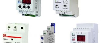
Application of devices
Three-phase voltage relay ZUBR 3F
Three-phase control relays are used to protect the electric motor from load in everyday life and industrial areas. They help to work correctly:
- air conditioning systems;
- refrigeration equipment;
- compressor units.
The device is indispensable for any equipment with an ATS circuit and other devices operating on an electric motor load. Helps avoid emergency situations.
Device marking
In order to mark control devices, a sequence of several symbols is applied to their front or side panels (sometimes it is indicated only in the passport). As an example, we consider a Russian-made device EL-13M-15 AC400V, designed for connection without a neutral wire. It is marked as follows:
- EL-13M-15 – series name;
- combination AC400V - permissible voltage.
The markings of imported models are slightly different. The PAHA series relay, which has the abbreviation PAHA B400 AA 3 C, is deciphered in more detail:
- B400 – operating voltage 400 Volts.
- A – type of adjustment.
- A (E) – mounting method (on a DIN rail or on a connector).
- 3 – body dimensions in mm.
The symbol "C" means the end of the code combination.
Device Features
There are different types of relays. They are produced taking into account the needs of problematic networks in which power outages and interference are possible. The devices are capable of delaying if a voltage sag occurs.
The three-phase voltage relay is installed in the panel on a special DIN rail. It weighs very little and has simple settings.
Installation is carried out parallel to the load, but the operation does not depend on power. At the outputs, the relay is equipped with closed and open groups of contacts, which are independent of each other and switch loads up to 5A.
Device marking
In order to mark control devices, a sequence of several symbols is applied to their front or side panels (sometimes it is indicated only in the passport). As an example, we consider a Russian-made device EL-13M-15 AC400V, designed for connection without a neutral wire. It is marked as follows:
- EL-13M-15 – series name;
- combination AC400V - permissible voltage.
The markings of imported models are slightly different. The PAHA series relay, which has the abbreviation PAHA B400 AA 3 C, is deciphered in more detail:
- B400 – operating voltage 400 Volts.
- A – type of adjustment.
- A (E) – mounting method (on a DIN rail or on a connector).
- 3 – body dimensions in mm.
The symbol "C" means the end of the code combination.
Principle of operation
The principle of load distribution between consumers
The operation of the device is based on the principle of self-return. If an emergency occurs, the equipment is switched off. When the relay receives three-phase voltage, it checks all parameters. If everything is normal, the built-in electromagnetic device turns on.
If there are malfunctions, the relay turns off, and after the parameters return to normal, it turns on without delay.
During the entire service life, the device monitors the voltage level and turns off the load in the event of:
- loss of any phase;
- phase imbalance;
- phase rotation violations.
The device is designed to control the quality of electrical energy. It provides reliable protection of equipment from sudden changes in voltage in the network.
Main types of relays and their purpose
Manufacturers configure modern switching devices in such a way that operation occurs only under certain conditions, for example, when the current flowing to the input terminals of the control unit increases. Below we will briefly look at the main types of solenoids and their purpose.
Electromagnetic relays
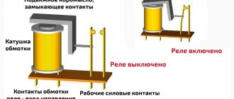
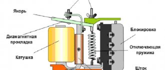
An electromagnetic relay is an electromechanical switching device, the operating principle of which is based on the effect of a magnetic field created by a current in a static winding on the armature. This type of control unit is divided into electromagnetic (neutral) devices, which respond only to the value of the current supplied to the winding, and polarized ones, the operation of which depends on both the current value and polarity.
Operating principle of an electromagnetic solenoid
Electromagnetic relays used in industrial equipment are in an intermediate position between high-current devices (magnetic starters, contactors, etc.) and low-current equipment. Most often this type of relay is used in control circuits.
AC Relay
This type of relay, as the name suggests, operates when an alternating current of a certain frequency is applied to the winding. This switching device for alternating current with or without phase zero crossing control is a block of thyristors, rectifier diodes and control circuits. AC relays can be made in the form of modules based on transformer or optical isolation. These KU are used in AC networks with a maximum voltage of 1.6 kV and an average load current of up to 320 A.
Intermediate relay 220 V
Sometimes the operation of the electrical network and devices is not possible without the use of a 220 V intermediate relay. Typically, a control unit of this type is used if it is necessary to open or open multidirectional contacts of a circuit. For example, if a lighting device with a motion sensor is used, then one conductor is connected to the sensor, and the other supplies electricity to the lamp.
AC relays are widely used in industrial equipment and home appliances
It works this way:
- supplying current to the first switching device;
- from the contacts of the first KU, the current flows to the next relay, which has higher characteristics than the previous one and is capable of withstanding currents with high values.
Every year relays become more efficient and compact
The functions of the small size 220V AC relay are very diverse and are widely used as an auxiliary device in a variety of fields. This type of control unit is used in cases where the main relay cannot cope with its task or when there are a large number of controlled networks that are no longer able to service the head unit.
The intermediate switching device is used in industrial and medical equipment, transportation, refrigeration equipment, televisions and other household appliances.
DC relay
DC relays are divided into neutral and polarized. The difference between them is that polarized DC ICs are sensitive to the polarity of the applied voltage. The armature of the switching device changes direction of movement depending on the power poles. Neutral DC electromagnetic relays are independent of voltage polarity.
Electromagnetic DC control units are mainly used when there is no possibility of connecting to an AC electrical network.
Four-pin automotive relay
The disadvantages of DC solenoids include the need to use a power supply and higher cost compared to AC control units.
This video demonstrates the connection diagram and explains the operating principle of a 4-pin relay:
Watch this video on YouTube
Electronic relay
Electronic control relay in the device circuit
Having understood what a current relay is, let’s consider the electronic type of this device. The design and principle of operation of electronic relays are practically the same as in electromechanical control units. However, to perform the necessary functions, an electronic device uses a semiconductor diode. In modern vehicles, most relay and switch functions are performed by electronic relay control units and at the moment it is impossible to completely abandon them. For example, a block of electronic relays allows you to control energy consumption, the voltage at the battery terminals, control the lighting system, etc.
Connection diagram and installation of voltage relay
The device will perform its functions regardless of the position. But each model has its own connection diagram. You can see it on the body.
For all devices, there are the same rules that are designed to control the process of connecting the relay to the electrical circuit.
The input contacts are connected to the network through a contactor or starter. The conductors of all phases are combined with the terminals, which are located on the top of the device. Elements are marked like this:
- Phases with letters A, B and C.
- N – neutral wire terminal.
- 1,2,3 – lower terminals.
First, from terminal 1, the conductor is connected to the output of the coil, which is located in the contactor. Terminal 3 is connected to any phase. The second output is connected to the neutral conductor of a three-phase network.
The power elements are connected as follows:
- Each phase that supplies current is connected to the input terminal of the contactor.
- The conductors are connected to the output terminals.
- To connect neutral conductors, a common neutral bus is installed in the distribution panel.
To ensure reliable contact, special tips are used.
Cases of using phase control relays
Using the example of two phase control relays RKF-MO8 and RKF-MO5, I will explain typical schemes for using these devices.
Connection RKF-MO8
The presented relay model is reassigned to control the resistance of the electric motor winding. To implement this function, the device has a separate terminal, which is designed to connect the device to one of the phases after the contactor. The remaining three are needed to connect to the network in front of the contactor.
In situations where the parameters of the supplied current from the network are normal, but the resistance on the winding itself is less than 500 kOhm, the relay will be turned off and power will not be supplied. If the winding resistance value is more than 500 kOhm, the device goes into the analysis mode of all parameters of the supplied current, and if they deviate, it sends a signal to disconnect the operating equipment from the network. Shutdown in case of voltage drop is not performed immediately, but after a time specified by the user.
Connection RKF-MO5
The RKF-MO5 model differs from the previous one in that it works without the need to connect a controlled network. For normal operation of the device, a connection to a three-phase network in front of the contactor is sufficient. Connection to the latter is made through six terminals numbered 11, 12, 14, 21, 22 and 24.
Connection diagram
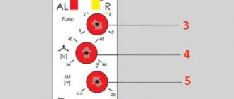
To set the upper and lower response thresholds, the RKF-MO5 has two switches. The values are set as a percentage. In addition, there is a switch responsible for the response delay.
RCD connection diagram
In apartments, connecting a three-phase network is rare. This option is popular for private homes. The protection device is connected in several ways:
- A 380 V 2-pole voltage relay is not suitable for home use. Use 4-pole analogues. 1 neutral conductor and 3 phase conductors are connected to them. The circuit is complicated by the fact that each line is equipped with its own RCD device. It is important to choose the right wires. For a single-phase network, the standard VVG version is suitable, but for a 3-phase network you need a fire-resistant VVGng.
- General RCD for 3-phase network + meter. The circuit contains an electricity meter. Group RCDs are located in the system for servicing individual lines. This scheme requires the installation of a large electrical panel with many wires and electrical appliances.
If an apartment or house has a large number of lighting and socket circuits, as well as a variety of household appliances, it is advisable to install double protection with a common RCD.
Pros and cons of domestic relays
Equipment developers and adjusters periodically have to choose between domestic and foreign automation manufacturers. On the one hand, you want to do everything cheaper, and on the other, more reliable. To make the right choice, you need to consider the pros and cons of each option.
Advantages of Russian control relays:
- Low price. Imported RKFs cost at least 2 times more.
- The device can operate at temperatures below –25°C. Among foreigners, such endurance is less common.
- Russian EL series relays do not require additional 24 V power supply. Most foreign relays require an additional voltage source.
Devices produced by the Electrical Engineering Company Meander Disadvantages of Russian RKFs:
- High heat dissipation. This indicates unreliability of power contacts or high consumption of auxiliary current.
- Incorrect operation of RKF analog circuits. Sensitivity to external interference.
- Outdated appearance. Although in the last decade there has been a “thaw” in terms of the design of domestic automation.
General settings of three-phase relay
In order for the 3-phase voltage control relay to work, you need to make some settings. After connecting the device to the electrical circuit, power is supplied to it, and the following information appears on the display:
- If the image on the display blinks, this indicates a lack of voltage.
- The appearance of dashes indicates a violation of the phase sequence or the absence of one.
- If the display flashes for a long time, you should suspect that the contactor is not connected.
You can set up a three-phase voltage control relay using two built-in buttons; they have triangles on them. They are located on the right side of the device: the top button with a triangle up, and the bottom button down. To get the maximum shutdown limit, you need to press the top button. She lingers for a few seconds. After this, a number appears in the central screen displaying the factory level. The button must be pressed until the desired value appears. After settings, the device will be automatically programmed within ten minutes.
How to set the restart time
On the right side of the display there is a control button with a drawn clock. It must be pressed and held until the factory value appears. The time interval is 15 seconds. This means that after the voltage normalizes, the device will turn on the electricity again after this period of time.
Indicators can be reduced. A few clicks on the top or bottom button are enough for the necessary parameters to appear.
How to adjust phase imbalance
To configure, you must simultaneously press both triangular buttons. After this, you can see 50V on the display. This means that power will not be supplied to the network when the phase imbalance reaches this value. To decrease or increase a parameter, you need to set the time of one of the buttons.
What is a phase control relay
The presented device is designed to work with three-phase networks. Therefore, the phase control relay is mainly used to protect expensive, powerful industrial equipment, the breakdown of which can lead to significant financial losses or a complete shutdown of production.
The phase control relay prevents possible malfunctions of operating equipment, which can be caused by voltage surges or dips.
Phase control relay
It is worth noting that the device I am considering is necessary not only in factories, but also for ordinary household consumers. For example, to protect electric stoves, boilers, powerful climate control systems and other equipment operating from a three-phase network.
Principle of operation
As an engineer with extensive experience, I want to warn you that buying a 3-phase control relay is quite a task. And all because, depending on the specific model, they differ in the set of functions. Some devices support the ability to configure triggering when the voltage increases linearly or when phase rotation is incorrect. Others are only able to detect sudden changes in clearly defined parameters.
Important! The phase control relay cannot work as an independent device that detects deviations in electric current parameters and cuts off the connected equipment from the network. It can only work in conjunction with a contactor, to which, depending on the situation, the relay sends a signal to turn on or turn off consumers.
Functions
Depending on the model, the presented type of relay can perform the following types of control:
- Voltages The device sends a command to the contactor to turn off if the incoming voltage exceeds the specified parameters
- Phase rotation The supply is switched off when phases stick together or are incorrectly positioned relative to the powered device.
- Phase loss Trip is performed if there is no voltage supply on one of the phases.
- Phase imbalance A trip signal is sent if there are phase or linear changes in the network.
An example of a phase control relay that has maximum functionality is RKF-MO5.
Features of common types of voltage relays
Thanks to the voltage relay, during power surges the device will not burn out, the board will not melt, or the electric motor will not fail. The cost of the devices is considerable, but they pay for themselves. It is better to prevent accidents than to buy new equipment.
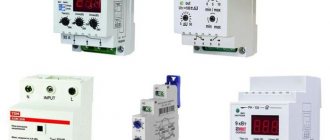
There are several types of control relays on the market from different manufacturers. They have the same principle of operation, although the design and set of additional functions may differ.
Modern devices have a digital display. It allows you to monitor the voltage level in three phases. There are also additional settings. With their help, they regulate the operation of the device and ensure simplicity and ease of use.
A three-phase voltage control relay is an indispensable thing in the household. It is not difficult to connect and configure. This will take no more than half an hour, after which all electrical appliances will be protected from voltage surges.
Advantages and differences between phase control relays and voltage relays
At first glance, it may seem that both types of relays perform the same functions. However, if you understand the functions of the voltage relay, significant differences in these devices become visible.
The main advantages of phase control relays include:
- the device is not affected by the EMF of the network and operates solely on the basis of current values;
- has the ability to protect powered equipment, for example, electric motor windings;
- control is performed over several network parameters, and not just one, like with a voltage relay.
In addition, the phase control relay is capable of capturing back EMF. The latter occurs in situations when one of the 3 phases disappears in the supply, while the remaining two are enough to operate the electric motor. The relay cuts off the current supply even before the moment when the EMF can cause harm to electrical equipment.
How I installed a voltage relay in an apartment panel
To avoid any questions, I’ll say right away that there is no need to install a contactor, since theoretically the voltage relay can withstand current up to 30 A, and according to the markings on the internal relay - up to 40 A. But this is theoretical, but how in practice - time will tell, I will definitely inform you additionally , just in case. And there is also a banal reason - there is simply no room in the shield. This is also the main reason why I did not install a bypass machine.
The current is limited to 16 A machines. But if, all other things being equal, there were 25 A machines, then it would be worth seriously thinking about a contactor. And about replacing them with 16 A, since the wiring is made of aluminum with a cross-section of 4 mm2.
During the installation process, I used a solid wire with a cross section of 2.5 mm2. Even if I wanted to use 4 squares, I wouldn’t be able to, because... The voltage relay terminals can only accept 2.5.
The most important connection point is the phase:
Phase connection when installing a voltage relay
To open it, I used the “Nut” compression. I consider it the most reliable way to connect wires, just like soldered twisting.
The photo shows how the wire after the meter enters the nut from below. It is aluminum, this is another argument in favor of “Nut”.
The second wire from the bottom from the “Nut” goes to power the relay (terminal 7). And two wires that come from the top of the “Nut” - a phase to the input of the voltage relay.
Why not two, and not one, and why not put a jumper between pins 1 and 2? The fact is that connecting 2 wires with a “Nut” is much more reliable than with a screw terminal. Secondly, as I said, putting 2 wires of 2.5 squares each into one terminal is problematic. Therefore, phase reliability is ensured by two wires at the input (for power), and by the fact that input contacts 1 and 2 are tightly soldered inside the relay (there is a photo with a proof in the first part of the article about this relay, the link was given above).
Output terminals 3 and 4 are also soldered inside the relay, and I screwed a wire to each terminal. But these wires do not connect anywhere else - they each go to their own machine (although a jumper would not hurt, but it is not required).
Installation of a voltage relay in the panel through the Walnut
I hope everything is clearly visible in the photo - after the machines, the phase wires (already aluminum) go to the apartment. The zero ones are connected to the terminals just above the machines.
For those interested in looking at everything in detail, I took a couple more photos of the installation:
Installation of voltage relay - top view
An example of installing a voltage relay in an apartment panel
A small life hack: in critical places I try not to just insert the stripped end of the wire into the terminal, but make a loop. This way I double the contact area (and reduce the notorious contact resistance), and eliminate the possibility of twisting the wire if the clamp is loosened. And the mechanical strength of the connection only benefits from this.
Anticipating comments regarding the ugly editing, I will say that I did this during Sunday prime time, and my main concern was disturbing the neighbors during their television evening. This is sacred)
Yes, beauty is not my element, but I vouch for reliability!
Here's what happened in the end:
The result of installing the FiF voltage control relay
The operating range was set to 175-245 V. I believe that this is the widest possible range, suitable for those who do not want this relay to operate frequently. If the safety of equipment is a priority, you can narrow the range a little, about 5 V at both ends.
Almost a year has passed since installing this relay, the flight is normal. There were a couple of low voltage outages, nothing more to say.
ASP series devices
In a separate row are the fully digital protective relays of the ASP series. In most of them it is no longer possible to find tuning elements for analog signals. Potentiometers depend on the influence of the external environment, quickly age, values change, and contact often disappears.
Digital devices do not contain contact mechanical parts, due to which the effect of external factors is reduced and their reliability increases. In appearance, the devices differ in their digital display. Their prices are on average higher, but you can also find budget items.
Three-phase voltage monitoring relay: purpose and application
Prerequisites
Three-phase power supply is used not only to connect consumers that load three phases at the same time.
Residential buildings in all populated areas, holiday villages, the private sector, administrative buildings and more are also connected to a three-phase network. But at the same time they are consumers of a 220 Volt phase network.
And all three phases are distributed among consumers so that presumably the same load is obtained for each phase.
Schematically, a network with three voltage phases is depicted as an equilateral triangle. Its vertices are phases A, B and C. The length of each side corresponds to a value of 380 Volts in the absence of load or when its value is small.
The median segment from the vertex to the intersection point of the medians is the phase voltage. With a symmetrical load, the length of each side, that is, the linear value, decreases equally. The same applies to phase values.
But since real consumers can be anything, the load always turns out to be asymmetrical.
Advice
And therefore the triangle turns out to be scalene, illustrating voltage deviations from 380 and 220 Volts. It is clearly noticeable that with an asymmetric load, all phase quantities have changed. Therefore, consumers connected to a phase with minimal voltage and who are grinding coffee at this time will not be able to prepare it efficiently. Coffee grinders will operate at reduced speed.
Three-phase electric motors, especially loaded ones, will begin to work with rotor swings. And this can lead to destruction of conveyor belts and cables due to jerking.
It will be even worse for all consumers without exception if the neutral breaks. In this case, the change in phase voltages can significantly exceed 220 Volts. And this is dangerous for household electrical appliances.
Not to mention loaded three-phase motors.
Principle of operation
To avoid problems that arise in the load due to phase imbalance, zero breaks, or incorrect phase sequence, it is turned off with a special relay.
There are many models of such relays on the market, more or less complex in design. Some of them use semiconductor devices and even microprocessors.
For electrical networks in residential buildings, cottages and the private sector, three-phase voltage relays are installed at distribution substations.
Industrial enterprises use all three connection phases everywhere. Therefore, three-phase voltage relays are used more widely, mainly to protect electric motors. It has contacts designed to control magnetic starters and switches.
The voltage control relay coils in a three-phase network are triggered by a signal that is separated from the electrical network by special harmonic filters. When such a signal appears, the coil of the starter or similar switch is de-energized by the relay contacts and the load is turned off.
Most models of such relays are equipped with regulators for setting certain parameters to obtain the necessary controlled values of three-phase voltage and the time between disconnecting and reconnecting the load.
The operation of the relay to protect the load from mismatch of three-phase network parameters occurs most often in automatic mode.
note
Human intervention is usually only required for long-term accidents. In such cases, repeated trips occur, and then you have to manually turn off the input switch. But it is possible to automate this process. After several repeated turns on and off, a signal will be generated to automatically turn off the input switch.
Example of a panel circuit
To give you an idea of what a surge protection circuit is, see the image below.
Typical diagram of a home electrical panel with a single-phase voltage relay (the meter is located outside the apartment)
If you assemble a similar electrical panel yourself from purchased components, we recommend that you take this important nuance into account.
The selection of a voltage relay must be made after the parameters of the input circuit breaker have been determined. In this case, the maximum current for the relay must be selected greater than that of it, from the following standard range of values:
Standard parameters of circuit breakers
But it is recommended to compare two options for disconnecting the load:
- directly by voltage relay contacts;
- an additional switch controlled by a voltage relay.
It is possible that the option with an additional switch will be cheaper and, for this reason, preferable.
Relay connection diagram via magnetic starter
For optimal performance, the voltage relay must be adjusted accordingly. This means that its settings must correspond to the characteristics of electricity consumers that are located after it and are connected to it. The wide variety of household electrical appliances also affects their attitude to changes in the supply voltage. First of all, this is due to the fact that some of them are equipped with an internal stabilized power source.
Relay and contactor operation diagram
An additional connection of a contactor becomes advisable in cases where excessive currents are regularly switched. Such a scheme will cost much less than purchasing a relay with the appropriate parameters. The rated current of the relay will no longer matter, since the entire current load will fall on the contactor, which has the necessary safety margin. The only drawback of this scheme is a slight decrease in performance. In this case, it takes time for the relay to operate and additional time for the contactor to operate.
In order to connect them together, we first use a diagram for connecting the power phase wire from the machine at the input to input 1 of the contactor, that is, to its power circuit. A separate wire with a smaller cross-section is used for the phase input of the control relay, since the loads on it will be insignificant.
This wire is connected not only to the output contact of the machine, but also to the input terminal of the contactor. Since it has a small cross-section, being connected to the same socket with a normal wire, it can easily jump out. To avoid this situation, a thin conductor is wound onto a thick wire and covered with a layer of solder. Sometimes crimping is done for such twisting using a special tip.
The relay output also uses a small cross-section wire connected to terminal 1 of the contactor coil. Terminal 2 together with the relay neutral wire are connected to the common neutral bus without any problems.
Features of the operation of voltage relays in three-phase networks
Three-phase voltage relay - connection diagram
In three-phase circuits, a particular danger is the activation of a relay with reduced voltage, the connection diagram of which does not provide for single-phase operation of the device. In most cases, in industrial networks, a separate load is connected to each phase. This leads to the fact that the overload response of one section of the ILV leads to its complete shutdown.
An exception is the situation when the facility predominantly uses three-phase equipment (machines with asynchronous motors, pumps, etc.). In this case, each of the phases is loaded more evenly and voltage overload practically does not occur.
Design and operating principle of RKF
The main operation of the device is performed by a microcircuit that is capable of detecting network disturbances and transmitting a command to an electromagnetic relay, which activates a contact that disconnects the load. These elements are placed in a compact housing with a mount for installation on a DIN rail. The front panel contains a response time regulator and device operation indicators. Sometimes there may be additional controls - settings for settings and restart times.
When three-phase voltage is supplied, the device tests the compliance of the electrical network parameters and, if violations are detected, prevents the equipment from starting. If a violation is detected during operation of the mechanism, the device makes an emergency stop. The indicator will display “Alarm” (red LED), and on some models - a specific reason.
Purpose of controls and indicators on the front panel of the device
