Sequence of actions for converting an ATX power supply into a regulated laboratory one.
1. Remove jumper J13 (you can use wire cutters)
2. Remove diode D29 (you can just lift one leg)
3. The PS-ON jumper to ground is already installed.
4. Turn on the PB only for a short time, since the input voltage will be maximum (approximately 20-24V). This is actually what we want to see. Don't forget about the output electrolytes, designed for 16V. They might get a little warm. Considering your “bloatiness”, they will still have to be sent to the swamp, no shame. I repeat: remove all the wires, they are in the way, and only ground wires will be used and +12V will then be soldered back.
5. Remove the 3.3-volt part: R32, Q5, R35, R34, IC2, C22, C21.
6. Removing 5V: Schottky assembly HS2, C17, C18, R28, or “choke type” L5.
8. Changing the bad ones: replace C11, C12 (preferably with a larger capacity C11 - 1000uF, C12 - 470uF).
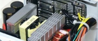
9. We change the inappropriate components: C16 (preferably 3300uF x 35V like mine, well, at least 2200uF x 35V is a must!) and resistor R27 - you no longer have it, and that’s great. I advise you to replace it with a more powerful one, for example 2W and take the resistance to 360-560 Ohms. We look at my board and repeat:
10. We remove everything from the legs TL494 1,2,3 for this we remove the resistors: R49-51 (free the 1st leg), R52-54 (2nd leg), C26, J11 (3rd leg)
11. I don’t know why, but my R38 was cut by someone