Network filter circuits for pulsed and high-frequency interference: 4 types of designs
Rule No. 2: high-quality UPSs must have a reliable filter for high-frequency signals in the design of the unit .
It is important to understand that high frequency pulses play a dual role:
- V/h interference can come from the household network to the power supply;
- high-frequency current pulses are generated by the built-in converter and exit it into the home wiring.
Reasons for interference in a household network:
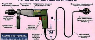
- aperiodic components of transient processes arising from switching powerful loads;
- operation of nearby devices with strong electromagnetic fields, for example, welding machines, powerful traction motors, power transformers;
- consequences of suppressed atmospheric discharge pulses and other factors, including the superposition of high-frequency harmonics.
Interference impairs the performance of electronic equipment, mobile devices and digital gadgets. They must be suppressed and blocked within the switching power supply design.
The filter is based on a choke made of two windings on one core.
Chokes can be made in different sizes, wound with thick or thin wire on large or small cores.
It is enough for a novice master to remember a simple rule: a filter with a large magnetic circuit inductor, an increased number of turns and a wire cross-section works better. (Principle: the more, the better.)
The inductor has inductive reactance, which sharply limits the high-frequency signal flowing through the phase or zero wire. At the same time, it does not have much effect on the current in the household network.
The operation of the inductor is effectively complemented by capacitive reactances.
The capacitors are selected in such a way that they short-circuit the interference signals weakened by the RF choke, directing them to ground potential.
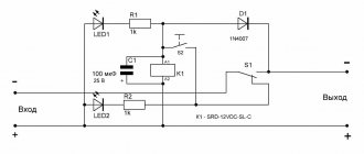
The principle of operation of the filter for high-frequency noise from penetration of input signals into the power supply is shown in the picture below.
Y capacitors are installed between the ground potentials with zero and phase. Their design feature is that in the event of a breakdown they are not capable of creating an internal short circuit and supplying 220 volts to the device body.
Between the phase and zero circuits, capacitors are placed that can withstand 400 volts, or better yet, 630. They are usually shaped like a parallelepiped.
However, you should be well aware that the UPSs in the voltage converter themselves correct the signal and interference practically does not interfere with them. Therefore, such a system is relevant for conventional analog blocks with output signal stabilization.
For a switching power supply, it is important to prevent RF interference from entering the household network. Another solution implements this feature.
As you can see, the principle is the same. It’s just that capacitive reactances are always located along the path of the interference behind the inductor.
The third circuit of the high-frequency filter is considered universal. She combined elements of the first two. The Y capacitors in it simply work on both sides of each inductor.
The most expensive and reliable devices use a complex filter with additionally connected chokes and capacitors.
I immediately show the arrangement of filters on all circuits of the power supply: input and output.
Please note that a ferrite filter, consisting of two detachable half-cylinders or made of a one-piece structure, can be additionally installed on the cable coming out of the UPS and connected to the electronic device.
An example of its use is a switching power supply for a laptop. This is already the fourth use of the filter.
UPS circuits
Before choosing a UPS scheme you need:
- set the input voltage level;
- determine the output range of the power supply unit;
- set the maximum power or load current.
Taking into account the specified parameters, the UPS design is selected. Selection can be made according to the type of regulatory components:
- bipolar transistors;
- field;
- specialized microcircuits.
The latter are the most convenient, since assembling a power supply based on them requires a minimum of additional parts. Their setup is simple and consists of selecting one parameter. A typical representative of such a chip for uninterruptible power supply devices is the UC3842. Single-ended converters have found application in laboratory experimental conditions, when the main criterion is small size and simplicity.
Mains voltage rectifier: the most popular design
Rule No. 3: after the output from the filter, the voltage is supplied to the rectifier circuit , which in the basic version consists of a diode bridge and an electrolytic capacitor.
During the electrical conversion, the shape of a sine wave, consisting of half-waves of opposite signs, first changes to a signal in a positive direction after the diode assembly, and then these pulsations are smoothed out to an almost constant amplitude value of 311 volts.
Such a network voltage rectifier is included in the operation of all power supplies.
Examination
In order to correctly assemble the power supply, you need to be careful about installing the polar elements, and you should also be careful when working with mains voltage. After disconnecting the unit from the power source, there should be no dangerous voltage remaining in the circuit. If assembled correctly, no further adjustment is required.
You can check the correct operation of the power supply as follows:
- We connect it to the circuit, the output is a light bulb, for example, 12 Volts. At the first short-term start, the light should be on. In addition, you should pay attention to the fact that all elements should not heat up. If something gets hot, it means the circuit is assembled incorrectly.
- At the second start, we measure the current value using a tester. Let the unit operate for a sufficient amount of time to ensure that there are no heating elements.
Pulse voltage converter: explanation in simple words with explanatory pictures
Rule No. 4: the rectified signal is subjected to pulse-width modulation on a power switch under the control of a PWM controller .
The power switch is made by the primary winding of a high-frequency transformer. For effective transformation of high-frequency pulses up to 100 kilohertz, the magnetic core structure is made of alsifer or ferrites.
The transformer winding receives signal pulses of several tens of kilohertz from the control circuits through an RF transistor.
Rectangular current pulses are supplied in time, alternating with pauses, and are designated by one (1) and zero (0).
The duration of the pulse or its width at each moment of low-frequency sinusoidal voltage corresponds to its amplitude: the larger it is, the wider the PWM. And vice versa.
The PWM controller monitors the value of the connected load at the output of the switching power supply. According to its value, it generates pulses that briefly open the power transistor.
If the power connected to the UPS begins to increase, then the control circuit increases the duration of the control pulses, and when it decreases, it decreases.
Due to the operation of this design, the voltage at the output of the unit is stabilized in a strictly defined range.
How to set up a switching power supply?
Actually, a power supply assembled on the basis of a working electronic ballast does not require any special adjustment.
It needs to be connected to the load equivalent and make sure that the power supply is capable of delivering the calculated power.
During a run under maximum load, you need to monitor the dynamics of the temperature rise of the transistors and transformer. If the transformer heats up too much, then you need to either increase the cross-section of the wire, or increase the overall power of the magnetic circuit, or both.
If the transistors get very hot, you need to install them on radiators.
If a home-wound inductor from a CFL is used as a pulse transformer, and its temperature exceeds 60... 65ºС, then the load power must be reduced.
It is not recommended to raise the temperature of the transformer above 60... 65ºС, and of transistors above 80... 85ºС.
Return to top menu
Pulse transformer: operating principle of one pulse in 2 cycles
Rule #5: The pulse transformer for the power supply transmits each PWM pulse due to two conversions of electromagnetic energy .
During the conversion of electrical energy to magnetic energy and back to electrical energy with reduced voltage, galvanic separation of the primary input circuits from the secondary output circuit is ensured.
Each PWM current pulse arriving when the power transistor is briefly opened flows through the closed circuit of the primary winding of the transformer.
Its energy is spent:
- first to magnetize the magnetic core;
- then to demagnetize it with current flowing through the secondary winding and additional charging of the capacitor.
According to this principle, each PWM pulse from the primary network recharges the storage capacitor.
UPS generators can operate using simple single-cycle or more complex push-pull construction technology.
Single-cycle switching power supply circuit: composition and principle of operation
On side 220 there are: a fuse, a rectifying diode bridge, a smoothing capacitor, a bipolar transistor, chains of an oscillating circuit and collector current, as well as windings of a pulse transformer.
A single-cycle switching power supply circuit is created to transmit power of 10÷50 watts, no more. It is used to make chargers for mobile phones, tablets and other digital gadgets.
The rectifier diode D7 is used in the output circuit of the transformer. It can be turned on in the forward direction, as shown in the picture, or reverse, which is important to consider.
When connected directly, the pulse transformer accumulates inductive energy and transfers it to the output circuit to the connected load with a time delay.
If the diode is turned back on, then the transformation of energy from the primary circuit to the secondary circuit occurs during the off state of the transistor.
The single-cycle UPS circuit is characterized by its simplicity of design, but large voltage amplitudes applied to the turns of the primary winding of the pulse transformer.
Their protection is carried out by additional chains of resistors R2÷R4 and capacitors C2, C3.
Push-pull switching power supply circuit: 3 design options
Higher efficiency and reduced power losses are the undeniable advantages of these UPSs compared to single-cycle models.
The simplest version of the full-wave technique is shown in the picture.
If you additionally connect two diodes and one smoothing capacitor to it, then a bipolar circuit is obtained using the same transformer.
It is common in power amplifiers and operates on the flyback principle. In it, smaller currents flow through each capacitor, providing an increased service life of the capacitors during operation.
You can extend the service life of electrolytic capacitors in a UPS by replacing one high-power capacitor with several components. The current will be distributed throughout, which will cause less heating. And heat removal from each individual is better.
The forward-flow power supply circuit has a choke in its design, which performs the function of energy storage. To do this, two diodes direct incoming PWM pulses to its input in the same polarity.
The choke of these devices is made in large dimensions and is installed separately inside the UPS board. It complements the operation of the storage capacitor.
This is clearly visible in the upper form of the signal shown by the rectification oscillogram of the same block without and with a choke.
The forward circuit is used in high-power power supplies, for example, inside a computer.
It uses Schottky diodes to rectify the current. They are used due to:
- reduced voltage drop on direct connection;
- and increased speed when processing high-frequency pulses.
3 diagrams of power stages of push-pull UPSs
In order of complexity of their implementation, generators perform the following:
- half-bridge;
- pavement;
- or the push-pull principle of constructing the output stage.
Half-bridge switching power supply circuit: overview
Capacitors C1, C2 are assembled in series with a capacitive divider. A constant supply voltage is supplied to it and the collector-emitter transitions of transistors T1, T2.
The primary winding of transformer Tr2 is connected to the midpoint of the capacitive divider and transistors. The output voltage of the generator is removed from its secondary winding, which is proportional to the input signal TP1, transformed to the bases T1 and T2.
The half-bridge UPS circuit works for loads ranging from a few watts to kilowatts. Its disadvantage is the possibility of damage to elements during overloads, which requires the use of complex protections.
Bridge Switching Power Supply Circuit: Brief Explanation
Instead of the capacitive divider of the previous technology, transistors T3 and T4 work here. They open in pairs together with T1 and T2: (pair T1-T4), (pair T2-T3).
The voltage of the emitter-collector transitions for closed transistors is not higher than the value of the supply voltage, and on the winding w1 TP3 it increases to the value U supply. Due to this, the efficiency value increases.
The bridge circuit is difficult to set up due to difficulties in setting up the control circuits of transistors T1÷T4.
Push-pull circuit: important features
The primary winding of the output TP2 has a middle terminal, to which the positive potential of the power source is supplied, and its minus is applied to the middle point of the secondary winding T1.
During the passage of one half-cycle of oscillation, one of the transistors T1 or T2 and the corresponding part of the transformer half-winding operate.
Here the highest efficiency, low ripple and low interference are created. The amplitude value of the pulse voltage on any half of the winding w1 TP2 reaches the value U power.
The self-inductive emf is added to the collector-emitter junction voltage of each transistor, and it increases to 2U power supply. Therefore, T1 and T2 must be selected at 600÷700 volts.
The push-pull circuit of the key cascade is more popular. It is used in the most powerful converters.
Power calculation
Repeating a ready-made power supply design does not require calculations. Copying the diagram and precise selection of components guarantees the specified parameters. The need for calculations appears if other characteristics of the block are needed or if there is a need to use other parts. The greatest difficulty is in selecting the required ferrite and calculating the pulse transformer. When using online calculators, set all parameters in comparable units - volts, watts.
Output Rectifier: The Most Popular Device
Rule #6: The signal coming from the UPS output is rectified and smoothed.
The simplest rectifier circuit, consisting of a diode and a storage capacitor, is shown in the picture below.
It can be modified by connecting additional capacitors, chokes, and filter elements.
Assembly and configuration of LBP
We recommend building this laboratory power supply in the following order:
- Assembling and testing a module with a bridge rectifier, filtering and relay, connecting to a transformer and activating a relay from an independent source to check the output voltages.
- Execution of the module for switching windings and monitoring radiator cooling. Running this module will make it easier to configure the future power supply. To do this, you will need another power source to supply a regulated voltage to the input of the system responsible for controlling the relay.
- The temperature portion of the circuit can be tuned by simulating the temperature. For this purpose, a heat gun was used, which gently heated a radiator with a sensor (BD135). Temperature was measured using a sensor included in a multimeter (at that time there were no ready-made accurate temperature meters). In both cases, the setup comes down to selecting PR201 and PR202 or PR301 and PR302, respectively.
- We then run the power supply by adjusting RV1 to produce a 0V output, which is useful for setting current limiting. The limitation itself depends on the values of resistors R18, R7, R17.
- Regulation of A/V indicators comes down to adjusting the reference voltages between pins 35 and 36 of the ICL microcircuits. Voltage and current meters used an external reference source. In the case of temperature meters, such precision is not needed, and the display with a decimal point is still somewhat exaggerated. Temperature readings are transmitted by one rectifier diode (there are three in the diagram). This is due to the PCB design. There are two jumpers on it.
- Directly at the output terminals, a voltage divider and a 0.01 Ohm / 5 W resistor are connected to the voltmeter, across which the voltage drop is used to measure the load current.
An additional element of the power supplies is a circuit that allows only one power supply to be turned on without the need for a second channel, despite the fact that the auxiliary transformer powers both channels of the power supply at once. On the same board there is a system for turning the power supply on and off using one low-current button (for each channel of the power supply).
The circuit is powered by an inverter, which in standby mode consumes about 1 mA from a 220 V network. All circuits can be downloaded in good quality in the archive