Metal detectors or metal detectors (from the English Metal Detector) are commonly called electronic devices for detecting metal objects located in water, soil, building walls and other environments. In Fig. Below is a moment of working with a metal detector underwater.
Working with a metal detector underwater
As search equipment, various modifications of metal detectors (hereinafter referred to as MI) are used in many areas of human activity, for example:
- To search for scrap metal, coins and jewelry in the ground, and to correct the location of hidden cables or utilities in the soil, ground detectors are used that effectively operate at a depth of up to 1 meter, or deep detectors with a detection depth of more than 3 meters;
- to detect explosive devices, military devices called mine detectors are used;
- manual inspection MI is adopted by security services to identify metal objects hidden on a person’s body or in his luggage.
Basic operating principle of MI
The operation of metal detectors is based on the practical implementation of the phenomenon of the occurrence of eddy currents when the electromagnetic field changes during its propagation in a physically inhomogeneous environment. At its core, a MI is an electronic device, when turned on, a directed primary signal is created that propagates its electromagnetic field in the environment.
The principle of operation of the metal detector is that when passing through objects with conductive properties (pieces of metal, minerals, elements of engineering communications, etc.), the magnetic field of the transmitted (primary) signal excites eddy currents on their surfaces, creating their own fields. As a result, the configuration and parameters of the primary signal field are distorted, which is recorded and processed by the receiving MI equipment. The parameters of the reflected signal inform about the presence of a metal object in the coverage area of the metal detector and its features. Depending on the level of complexity of the circuitry of various MI models, it is possible to determine the depth of the detected metal object and its type (gold, ferromagnetic alloy, non-ferrous or ferrous metal).
Note! Metals are not capable of emitting electromagnetic waves on their own in order to somehow “give out” their presence in the soil or in the thickness of concrete. Only irradiation with a directed signal emanating from the MI can excite a secondary signal from the metal target, which is often called a reflected or re-emitted signal.
In Fig. Below is a schematic diagram of the generation of a magnetic field of a secondary signal, which clearly explains how the metal detector works.
Scheme of electromagnetic field generation during MI operation
The above principle of operation of a metal detector, which requires irradiation of the environment/object under study with radio waves and decoding of the received reflected signals, is basic for all modern serial detectors. A compact hand-held metal detector for a security officer at a large shopping center and an arched metal detector at an international airport, the frame height of which exceeds 2 meters, work on the same principle.
GENERAL ISSUES
1.1. Work principles
Metal detector based on the “transmission-reception” principle
The terms “transmit-receive” and “reflected signal” in various detector devices are usually associated with methods such as pulse echo and radar, which is a source of confusion when it comes to metal detectors. Unlike various types of locators, in metal detectors of this type both the transmitted (emitted) and received (reflected) signals are continuous, they exist simultaneously and coincide in frequency.
The operating principle of transmit-receive metal detectors is to register a signal reflected (or, as they say, re-emitted) by a metal object (target), see [4], pp. 225-228. The reflected signal arises due to the influence of the alternating magnetic field of the transmitting (emitting) coil of the metal detector on the target. Thus, a device of this type implies the presence of at least two coils, one of which is transmitting and the other is receiving.
The main fundamental problem that is solved in metal detectors of this type is the choice of the relative arrangement of the coils, in which the magnetic field of the emitting coil, in the absence of foreign metal objects, induces a zero signal in the receiving coil (or in the system of receiving coils). Thus, it is necessary to prevent direct impact of the transmitting coil on the receiving coil. The appearance of a metal target near the coils will lead to the appearance of a signal in the form of an alternating electromotive force (emf) in the receiving coil.
At first it may seem that in nature there are only two options for the relative arrangement of coils, in which there is no direct signal transmission from one coil to another (see Fig. 1, a and b) - coils with perpendicular and crossing axes.
Rice. 1. Options for the relative arrangement of metal detector sensor coils based on the “transmission-reception” principle
A more thorough study of the problem shows that there can be as many different systems of metal detector sensors as desired. But these are more complex systems with more than two coils, electrically connected accordingly. For example, in Fig. 1, c shows a system of one emitting (in the center) and two receiving coils, connected counter-currently according to the signal induced by the emitting coil. Thus, the signal at the output of the system of receiving coils is ideally equal to zero, since the emf induced in the coils. mutually compensated.
Of particular interest are sensor systems with coplanar coils (i.e. located in the same plane). This is explained by the fact that metal detectors are usually used to search for objects located in the ground, and bringing the sensor closer to the minimum distance to the surface of the earth is possible only if its coils are coplanar. In addition, such sensors are usually compact and fit well into protective housings such as “pancake” or “flying saucer”.
The main options for the relative arrangement of coplanar coils are shown in Fig. 2, a and b. In the diagram in Fig. 2, and the relative position of the coils is chosen such that the total flux of the magnetic induction vector through the surface limited by the receiving coil is equal to zero. In the diagram of Fig. 2, b one of the coils (receiving) is twisted in the form of a “figure of eight”, so that the total emf induced on the halves of the turns of the receiving coil located in one wing of the “figure of eight” compensates for a similar total emf induced in the other wing of the G8. Various other designs of sensors with coplanar coils are also possible, for example Fig. 2, e.
Rice. 2. Coplanar options for the relative arrangement of metal detector coils according to the “transmission-reception” principle
The receiving coil is located inside the emitting coil. The emf induced in the receiving coil. is compensated by a special transformer device that selects part of the signal from the emitting coil.
Beat metal detector
The name “beat metal detector” is an echo of the terminology adopted in radio engineering since the days of the first superheterodyne receivers. Beats are a phenomenon that most noticeably manifests itself when two periodic signals with similar frequencies and approximately equal amplitudes are added and consists of a pulsation in the amplitude of the total signal. The ripple frequency is equal to the difference in frequencies of the two added signals. By passing such a pulsating signal through a rectifier (detector), it is possible to isolate the difference frequency signal. Such circuitry has been traditional for a long time, but currently it is no longer used either in radio engineering or in metal detectors. In both cases, amplitude detectors were replaced by synchronous detectors, but the term “on beats” remains to this day.
The principle of operation of a beat metal detector is very simple and consists in recording the frequency difference from two generators, one of which is stable in frequency, and the other contains a sensor - an inductor in its frequency-setting circuit. The device is adjusted in such a way that, in the absence of metal near the sensor, the frequencies of the two generators coincide or are very close in value. The presence of metal near the sensor leads to a change in its parameters and, as a consequence, to a change in the frequency of the corresponding generator. This change is usually very small, but the change in the frequency difference between the two oscillators is already significant and can be easily recorded.
The frequency difference can be recorded in a variety of ways, from the simplest, when the difference frequency signal is listened to on headphones or through a loudspeaker, to digital methods of frequency measurement. The sensitivity of a metal detector to beats depends, among other things, on the parameters for converting changes in the impedance of the sensor into frequency.
Typically, the conversion consists of obtaining the difference frequency of a stable generator and a generator with a sensor coil in the frequency-setting circuit. Therefore, the higher the frequencies of these generators, the greater the frequency difference will be in response to the appearance of a metal target near the sensor. Registration of small frequency deviations presents a certain difficulty. Thus, by ear you can confidently register a shift in the frequency of the tone signal of at least 10 Hz. Visually, by blinking the LED, you can register a frequency shift of at least 1 Hz. In other ways, it is possible to achieve registration of a smaller frequency difference, however, this registration will require considerable time, which is unacceptable for metal detectors that always operate in real time.
The method of isolating a small frequency difference between two generators gives rise to a significant technical problem - phase locking. The problem is that two oscillators tuned to very close frequencies tend to synchronize with each other. This synchronization manifests itself in the fact that when trying to bring the difference frequency of two generators closer to zero in some way, when the difference frequency reaches a certain threshold, an abrupt transition occurs to the state of the generators when their frequencies coincide. Generators become synchronized. Physically, the phenomenon of phase locking is explained by nonlinearities that are inevitably present in any generator, and parasitic penetration of the signal from one generator into another (through power circuits, through parasitic capacitances, etc.). As practice shows, if you do not resort to special tricks such as optoelectronic decoupling of generators, then for the difference frequency you can actually obtain a threshold for the onset of parasitic synchronization of the order of 10-4 relative to the frequency of the generators. From here you can get an estimate for the frequency at which the metal detector should operate on beats in order to obtain maximum sensitivity of 10 ... 100 kHz and higher.
Selectivity for metals at such frequencies, which are very far from optimal, is very weak. In addition, it is almost impossible to determine the phase of the reflected signal from the generator frequency shift. Therefore, the metal detector has no selectivity on beats.
The response of the device to a metal object is inversely proportional to the sixth power of the distance. It is almost the same as that of metal detectors based on the “transmission-reception” principle. However, the detection range of this type of device is usually much worse due to the effect of parasitic synchronization.
Metal detector based on the principle of an electronic frequency meter
The development of measuring electronic technology, and especially with built-in microprocessors, now allows us to take a different look at metal detectors, the operating principle of which is based on measuring the frequency shift of the measuring oscillatory circuit. Modern technical means make it possible to implement a compact device that allows small deviations in the frequency of the measuring generator to be assessed in real time with high accuracy. And although an electronic metal detector built on this principle is an undoubted relative of a “beating” device, it deserves to be classified as a separate class of devices that can be called metal detectors based on the principle of an electronic frequency meter. Devices of this class, in addition to the mass of service capabilities of the microprocessor implementation, have another fundamental difference from the simplest “beat” devices - the ability to evaluate the sign of the frequency increment. Considering that a ferromagnetic target usually leads to a decrease in the frequency of the measuring oscillator, and a target made of a non-ferromagnetic metal - to an increase, we have an excellent opportunity to select targets according to the type of metal. In addition, this class of devices is practically not subject to the parasitic synchronization effect described above, since the frequency of the measuring generator and the frequencies of other auxiliary signals (microprocessor clock frequency) are very different. This allows for increased sensitivity.
A positive side for practice is the simplicity of the design of the sensor and the electronic part of metal detectors based on beats and on the principle of a frequency meter. Such a device can be very compact. It is convenient to use when something has already been detected by a more sensitive device. If the discovered object is small and located deep enough in the ground, then it can “get lost” or move during the excavation. In order not to “look through” the excavation site many times with a bulky, sensitive metal detector, it is advisable to control its progress at the final stage with a compact, short-range device, which can be used to more accurately determine the location of the object.
Single Coil Induction Metal Detector
The word “induction” in the name of metal detectors of this type fully reveals the principle of their operation, if you remember the meaning of the word “inductio” (Latin) - guidance. A device of this type contains a sensor of one coil of any convenient shape, excited by an alternating signal. The appearance of a metal object near the sensor causes the appearance of a reflected (re-emitted) signal, which “induces” an additional electrical signal in the coil. All that remains is to highlight this additional signal.
The induction-type metal detector has gained the right to life, mainly due to the main drawback of devices based on the “transmission-reception” principle - the complexity of the design of the sensors. This complexity leads either to the high cost and complexity of manufacturing the sensor, or to its insufficient mechanical rigidity, which causes false signals to appear when moving and reduces the sensitivity of the device.
Rice. 3. Block diagram of the input unit of an induction metal detector
If you set yourself the goal of eliminating this drawback from devices based on the “transmission-reception” principle by eliminating its very cause, then you can come to an unusual conclusion - the emitting and receiving coils of the metal detector must be combined into one! In fact, in this case there are no very undesirable movements and bends of one coil relative to the other, since there is only one coil and it is both emitting and receiving. The sensor is also extremely simple. The price for these advantages is the need to isolate the useful reflected signal from the background of a much larger excitation signal of the emitting/receiving coil.
The reflected signal can be isolated by subtracting from the electrical signal present in the sensor coil a signal of the same shape, frequency, phase and amplitude as the signal in the coil in the absence of metal nearby. *How this can be implemented in one of the ways is shown in Fig. 3.
The generator produces an alternating voltage of a sinusoidal shape with a constant amplitude and frequency. The voltage-to-current converter (VCT) converts the generator voltage Ur into current Ig, which is supplied to the oscillatory circuit of the sensor. The oscillating circuit consists of a capacitor C and a sensor coil L. Its resonant frequency is equal to the frequency of the generator. The PNT conversion coefficient is selected such that the voltage of the oscillatory circuit id is equal to the generator voltage Ur (in the absence of metal near the sensor). Thus, the adder subtracts two signals of the same amplitude, and the output signal - the result of the subtraction - is equal to zero. When metal appears near the sensor, a reflected signal occurs (in other words, the parameters of the sensor coil change), and this leads to a change in the voltage of the oscillating circuit 11d. A non-zero signal appears at the output.
In Fig. Figure 3 shows only the simplest version of one of the diagrams of the input part of metal detectors of the type under consideration. Instead of a PNT in this circuit, it is in principle possible to use a current-setting resistor. Various bridge circuits can be used to turn on the sensor coil, adders with different transmission coefficients for inverting and non-inverting inputs, partial connection of an oscillating circuit, etc.
In the diagram in Fig. 3 an oscillatory circuit is used as a sensor. This is done for simplicity in order to obtain zero phase shift between the Ur and 11d signals (the circuit is tuned to resonance). You can abandon the oscillatory circuit with the need to fine-tune it for resonance and use only the sensor coil as a PNT load. However, the PNT gain for this case must be complex to correct for the 90° phase shift resulting from the inductive nature of the PNT load.
Pulse metal detector
In the types of electronic metal detectors discussed earlier, the reflected signal is separated from the emitted one either geometrically - due to the relative position of the receiving and emitting coils, or using special compensation circuits. Obviously, there may also be a temporary method for separating the emitted and reflected signals. This method is widely used, for example, in pulse echo and radar. During location, the mechanism of delay of the reflected signal is due to the significant time it takes for the signal to propagate to the object and back.
In relation to metal detectors, such a mechanism may be the phenomenon of self-induction in a conductive object. How to use this in practice? After exposure to a magnetic induction pulse, a damped current pulse appears in a conducting object and is maintained for some time (due to the phenomenon of self-induction), causing a time-delayed reflected signal. It carries useful information and should be registered.
Thus, another scheme for constructing a metal detector can be proposed, fundamentally different from those discussed earlier in the method of signal separation. This type of metal detector is called a pulse detector. It consists of a current pulse generator, receiving and emitting coils, which can be combined into one, a switching device and a signal processing unit.
The current pulse generator generates short current pulses in the millisecond range that enter the emitting coil, where they are converted into magnetic induction pulses. Since the emitting coil - the load of the pulse generator - has a pronounced inductive nature, overloads in the form of voltage surges occur at the generator at the pulse fronts. Such bursts can reach tens to hundreds (!) of volts in amplitude, but the use of protective limiters is unacceptable, since it would lead to a delay in the front of the current pulse and magnetic induction and, ultimately, to complicate the separation of the reflected signal.
The receiving and emitting coils can be positioned relative to each other quite arbitrarily, since the direct penetration of the emitted signal into the receiving coil and the effect of the reflected signal on it are separated in time. In principle, one coil can serve as both a receiving and an emitting coil, but in this case it will be much more difficult to decouple the high-voltage output circuits of the current pulse generator from the sensitive input circuits.
The switching device is designed to perform the above-mentioned separation of the emitted and reflected signals. It blocks the input circuits of the device for a certain time, which is determined by the duration of the current pulse in the emitting coil, the discharge time of the coil and the time during which short responses of the device from massive weakly conductive objects such as soil are possible. After this time, the switching device must ensure the transmission of the signal from the receiving coil to the signal processing unit.
The signal processing unit is designed to convert the input electrical signal into a form convenient for human perception. It can be designed based on solutions used in other types of metal detectors. The disadvantages of pulse metal detectors include the difficulty of implementing in practice the discrimination of objects by type of metal, the complexity of the equipment for generating and switching current and voltage pulses of large amplitude, and the high level of radio interference.
Magnetometers
Magnetometers are a broad group of devices designed to change the parameters of a magnetic field (for example, the module or components of the magnetic induction vector). The use of magnetometers as metal detectors is based on the phenomenon of local distortion of the Earth's natural magnetic field by ferromagnetic materials, such as iron. Having detected with the help of a magnetometer a deviation from the module or direction of the magnetic induction vector of the Earth's field that is usual for a given area, we can confidently say that there is some magnetic inhomogeneity (anomaly) that can be caused by an iron object.
Compared to the previously discussed metal detectors, magnetometers have a much greater detection range of iron objects. It is very impressive to know that using a magnetometer you can register small shoe nails from a shoe at a distance of 1 m, and a car at a distance of 10 m! Such a large detection range is explained by the following. An analogue of the emitted field of conventional metal detectors for magnetometers is the uniform (on the search scale) magnetic field of the Earth. Therefore, the response of the device to an iron object is inversely proportional not to the sixth, but only to the third power of the distance.
The fundamental disadvantage of magnetometers is the inability to detect objects made of non-ferrous metals with their help. In addition, even if we are only interested in iron, the use of magnetometers for searching is difficult - in nature there is a wide variety of natural magnetic anomalies of various scales (individual minerals, mineral deposits, etc.). However, when searching for sunken tanks and ships, such devices are unrivaled!
Radars
It is a well-known fact that with the help of modern radars it is possible to detect an aircraft at a distance of several hundred kilometers. The question arises: does modern electronics really not allow us to create a compact device that allows us to detect objects of interest to us at least at a distance of several meters?9 The answer is a number of publications in which such devices are described.
Typical of them is the use of the achievements of modern microwave microelectronics and computer processing of the received signal. The use of modern high technologies makes it almost impossible to independently manufacture these devices. In addition, their large overall dimensions do not yet allow them to be widely used in field conditions.
The advantages of radars include a fundamentally higher detection range - the reflected signal, in a rough approximation, can be considered to obey the laws of geometric optics and its attenuation is proportional not to the sixth or even the third, but only to the second power of the distance.
MI frequency range
What is a diode - operating principle and device
The operating frequency range of modern metal detectors is from 1 kHz to 30 MHz.
Breakdown of the frequency parameters of serial MI into the main operating ranges of search coils, indicating the accepted designations in foreign and Russian classification
| Operating frequency range | English designation | Russian designation |
| From 3 kHz to 30 kHz | VLF - Very Low Frequency | VLF - ultra-low frequencies |
| 30 kHz to 300 kHz | LF - Low Frequency | LF – low frequencies |
| 300 kHz to 3 MHz | MF - Medium Frequency | MF – mid frequencies |
| 3 MHz to 30 MHz | HF - High Frequency | HF – high frequencies |
In the practice of prospecting work using MI, the operating frequencies of the primary signal are selected as follows:
- Low-frequency radio waves are more sensitive, compared to HF radiation, to targets made of metals with high electrical conductivity (gold, silver, copper and their alloys). LF signals penetrate deeply into the ground, so deep MIs, capable of detecting metal objects at a depth of up to 4 meters, operate at frequencies in the range of 2.5-6.6 kHz. At the same time, the sensitivity of the device to small targets decreases.
- High-frequency radio waves have increased sensitivity to metal targets with low electrical conductivity, made of aluminum, nickel, etc., but the penetration ability of HF radiation into soil is quite low. But high frequencies are capable of detecting small targets up to 1 mm in size.
- Mid-frequency radiation represents a kind of compromise between vlf (microwave) and hf (HF) signals and is considered suitable for searching for finds of any type.
How to set up a metal detector
Setting up a metal detector is a delicate matter. It depends on the target type, detector model and many related factors. It is impossible to give one specific formula. The operator selects the settings individually, practicing and experimenting. However, general principles still exist:
- Sensitivity - the higher the parameter is set, the deeper the device can detect the target. However, as this indicator increases, the level of interference increases, so setting the maximum is not recommended. If the search is carried out in a littered area, several nearby targets blur the signal and make the search difficult. In such cases, beginners are advised to lower the sensitivity threshold. Then the device will not react to nearby objects, which will allow you to more accurately localize the search target.
- Discrimination is a very important indicator. The result of the work directly depends on the success of its setup. Modern devices have programmed modes and an intuitive interface. You must select the required mode based on the device model. However, it should be noted that the accuracy of the discriminator decreases at greater depths. Therefore, for a beginner it is better to use the “All Metals” mode. This will allow you not to miss a valuable find.
Other settings depend on the specific metal detector model. Among them are ground balance, target designation, and sound signal. The most important of these is ground balancing, but this is most often adjusted automatically. The remaining indicators are adjusted according to the instructions and capabilities of the specific metal detector.
Basic equipment MI
Almost all modifications of serial and home-made metal detectors consist of functionally similar elements. In Fig. Below is the design of a typical MI indicating the main parts and modular blocks.
Design of a typical MI
Blocking generator: operating principle
The MI includes the following elements:
- A search coil that performs the functions of a radio transmitter and receiver of reflected signals. Structurally, the search coil is a plastic case (in most MI models - round or elliptical configuration), inside of which turns of stranded wire are placed. For sealing purposes, after laying the wires, the internal cavity of the housing is filled with a compound.
Important! It is generally accepted that MI search coils cannot be repaired, since the procedure of opening a monolithic housing for repair and refilling is a rather labor-intensive process. Most often, when an MI coil fails, it is simply replaced with a new one.
- Lower rod designed for:
- adjusting the angle of inclination of the search coil in order to ensure more accurate exploration of the area;
- rigid fixation of the coil after adjusting its spatial position.
- Middle rod used to connect the upper and lower rod. The middle rod is given the function of adjusting the length of the MI when adjusting to the height of the operator.
- The upper rod on which the control unit is located. The most convenient for use are considered to be products with an S-shaped upper rod, additionally equipped with:
- an armrest used to support the operator's elbow;
- a handle that provides convenient grip and retention of the device during search operations.
- A control unit that processes the information received from the search coil and provides the operator-user with the results of processing in the form of sound signals and digital data on the display. Is used for:
- visual and acoustic control of the search process;
- control the operation of MI equipment;
- settings of equipment operating modes.
In Fig. Below are shown the control unit separately and the metal detector included with this unit.
Metal detector and control unit
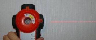
How to use a metal detector
Photo from the site www.garrett-shop.ru
A properly selected and configured metal detector is only half the battle. To work successfully, you need to learn how to use it correctly. It’s better not to rush while working. Divide the search area into zones and smoothly move the catcher as close to the ground as possible, moving it to the right and left. Having detected a target, the detector beeps. If it is clear, you have found a small coin-shaped object, and if it is intermittent, you have found an irregularly shaped object. With experience, you will be able to determine the size of a find and its depth by sound. Having heard the sound signal, you need to look at the device screen. Moving the pointer to the right allows you to classify the type of metal found. If we take the center as 0, then moving the arrow to 8-12 indicates gold, 26-28 indicates copper.
In conclusion, we can say that when searching for valuables, a metal detector is just an auxiliary device. The success of the work depends more on the skills and luck of the user himself. If you firmly want to become a professional treasure hunter, try, gain experience, and perhaps one day find a real treasure.
MI modifications
Operating principle of the electric motor
The designs of modern metal detectors depend on the methods of constructing the circuitry of the search apparatus. In accordance with the applied method of constructing the circuit, the following modifications of metal detectors are distinguished:
- Pulse MIs, also called PI metal detectors (from the English pulse induction). The principle of operation of a pulse device is to supply pulse signals to the search head coil, which create an electromagnetic field pulsating at a certain frequency. The turned on field induces eddy currents on the surface of the detected object. Immediately after turning off the inducing field, these currents die out, but not instantly, but over a short period of time, creating a damped signal that is picked up by the coil. Analysis of the parameters of the decaying magnetic “echo” allows us to judge the presence or absence of metal objects.
- Balanced MIs, according to foreign classification - TR-metal detectors (from transmitter-reciver - transmitter-receiver), operating using the induction balance method. The head of the device is equipped with two coils, carefully balanced to zero mutual induction. The analyzed parameters are:
- amplitude of the received signal;
- the phase shift between the sent and received signals.
Additional Information. The TR method in its pure form is practically never found due to difficulties with balancing the coil system. It is mainly used in combination with other methods, of which the most common is the VLF/TR method.
- VLF/TR are metal detectors whose circuitry operates at low operating frequencies.
- RF metal detectors (from radio frequency) operating in the high-frequency wave range with transmitting and receiving coils perpendicular to each other.
- BFO metal detectors, also called generator metal detectors. The device circuit is constructed using the beat method. During operation, the frequency of the LC generator, which includes the search coil, is measured. The readings are compared with reference frequency parameters, after which the resulting difference beat frequency is displayed on an acoustic indication (speaker).
In Fig. Below is a ground MI with a VLF circuit using a DD (DoubleD) coil.
VLF metal detector
Beat metal detector
The operating principle of a beat metal detector is based on the combination of the difference in frequencies emanating from two generators. One of these generators has a stable frequency, and the system of the second includes a sensor, which is an inductor. If metal objects are not located near the metal detector, the frequency values of the generators in the device are almost the same. The presence of metal near the sensor leads to a sharp change in the frequency of the generator.
Beat metal detector circuit
Registration of frequency differences can occur in a variety of ways. The simplest way is to listen to the signal using headphones or a loudspeaker. Digital methods for measuring frequency fluctuations are also often used.
Advantages and disadvantages of metal detectors
Any modification of the MI has its own advantages and disadvantages, characteristic of the applied technique for constructing the equipment circuit. Typical advantages and disadvantages of the above methods:
- PI metal detectors are effective for detecting metals in saline soils and sea water, but they do not recognize targets well and are very energy-consuming;
- TR metal detectors are highly sensitive and distinguish different types of metals well, however, as the depth increases, sensitivity to small targets is lost;
- VLF/TR – metal detectors are capable of distinguishing non-ferrous from ferrous metals, they have a high resolution, however, the rather complex circuitry makes it difficult to configure the device to the desired quality of work;
- RF metal detectors are quite versatile when used as deep detectors. They are not “distracted” by small metal debris and can detect pipes and even ore veins at a depth of 5-6 meters. Disadvantage: lack of sensitivity to small targets at shallow depths;
- BFO metal detectors have a relatively simple design; the search coil does not require precision design. The disadvantages of the application are low sensitivity, unstable operation on mineralized soils and in wet soil.
Device at home
Every person is quite capable of making a simple metal detector. In this case, the circuit of a simple metal detector made by yourself consists of: a radio repeater receiver, a microcalculator, and an ordinary box with a lid (made of cardboard, plastic). To connect individual elements of the circuit, 2-sided adhesive tape is used.
This detector belongs to the pulse category. The principle of operation is to determine the reversal of the direction of the EM field during excess radiation.
Procedure for manufacturing, setting, use:
- unfold the box. Apply 2-sided tape to the backs of the calculator and radio and secure the elements in the box. The receiver is preferably on the lid;
- turn on the radio receiver on medium waves; determine an area free from radio stations, with a minimum noise level;
- turn on the microcalculator, as a result the noise of the receiver will increase;
- in the absence of tone, a smooth adjustment is made by the search regulator;
- the box is folded until the background disappears or becomes smaller. Using improvised materials, the lid is fixed in this position.
As you approach the objects you are looking for, the device will begin to resonate and the noise will intensify.
What do metal detecting enthusiasts find?
Earthen soil acts as a kind of preservative in which old things are preserved for a long time. Search activity allows you not only to relax your soul in nature, but also to earn extra money by selling metal found in the depths of the earth or under water. With the help of MI, search engines manage to find treasures, valuables and military bronze artifacts, gold jewelry and non-ferrous scrap metal, coins from the times of Ancient Rus' and ancient crosses from the 16th-18th centuries. There are known cases of discovery of gold nuggets and iron meteorites. The use of MI in amateur research presupposes certain restrictions that do not allow targeted searches in the territories of archaeological heritage monuments or damage to the cultural layer.
Important! Items of historical value, ancient jewelry, weapons found in battlefields, and archaeological rarities must be handed over to government agencies. You should not turn your hobby into a criminal business.
In Fig. Below is a coin detected by the MI.
A metal detectorist's find
What is a conveyor metal detector?
The conveyor metal detector is designed to detect foreign inclusions from ferrous or non-ferrous metals and alloys in controlled products. This is a stationary device on stable wheels. It automatically scans objects on a moving conveyor belt. When metal objects or particles are detected at the metal detector, a sound and light indication is triggered and the conveyor stops. Further actions depend on the configuration: either the metal detector will wait for a manual restart after the operator has removed the rejected product, or the metal detector will reject the contaminated product on its own, moving it to a special container without interrupting operation.
Main elements of a conveyor metal detector
With a certain degree of confidence, we can say that foreign objects can get into any product during the production process. And this is not a matter of shortcomings in technological processes. There can be two reasons: periodic equipment breakdowns and human factor. As a result, fragments or parts of production equipment (nuts, bolts, springs, etc.), as well as foreign objects brought in by workers (paper clips, buttons, hairpins, coins, buttons, etc.) may get into the manufactured products.
Such metal products can be found both in raw materials and in the final product. They pose the greatest danger when they get into food. Therefore, the food industry is the main potential consumer of conveyor metal detectors.
Why do you need a conveyor metal detector?
There are several reasons:
- Quality control of incoming raw materials. Conveyor metal detectors increase the company's response speed. They allow you to timely reject inappropriate raw materials and stop cooperation with unscrupulous suppliers.
- Quality control of the final product. Not only the image of the enterprise, but also the health of consumers depends on this.
- Protection of metal detector related equipment. Detection of metal objects or inclusions at the early stages of the technological cycle makes it possible to avoid equipment breakdowns and financial costs for its repair. This applies to mixers, dough mixers, dough sheeters - equipment that can be damaged by foreign metal objects.
- Compliance with international quality standards - HACCP, ISO 22000:2005. These documents require a radical change in approaches to product quality control. At the same time, the interests of the consumer are put at the forefront. The presence of a HACCP or ISO 22000:2005 certificate of conformity improves the image of the enterprise and increases the degree of trust among consumers.
What is HACCP and ISO 22000:2005
On July 1, 2013, the Technical Regulations of the Customs Union TR CU 021/2011 “On the safety of food products” came into force in Russia. This document requires food manufacturers to develop, implement and maintain procedures based on HACCP principles.
HACCP, from English Hazard Analysis and Critical Control Point, translated means “Hazard Analysis and Critical Control Points”. This system is a set of developed documents, organizational structure, resources and production processes. Its implementation means that the enterprise fully complies with the requirements of TR CU 021/2011. The presence of a certificate allows you to apply the HACCP conformity mark to the packaging, which informs customers about the safety of the product.
ISO 22000:2005 “Management systems for food and food safety” also contains HACCP requirements, but is a more extensive document. It is more focused on enterprises supplying their products to European markets.
Simple DIY metal detector
You can assemble a simple MI yourself, using available radio parts from Soviet times. In Fig. Below is shown the structure of a generator-type MI circuit built using the beat method (BFO metal detector).
Circuit structure of a simple MI on transistors
The scheme is built from five main modules:
- a master oscillator that creates a reference frequency;
- a search generator, the frequency of which changes when a metal target is detected;
- a low-frequency amplifier that increases the signal difference between the generators;
- sound reproducing device (speaker);
- power supply.
On the Internet you can find dozens of diagrams of full-fledged metal detectors, for the assembly of which resistors, capacitors and transistors, which were produced back in Soviet times, will be useful.
Experts assure that the Russian population has at least two million metal detectors in their hands, allowing them to conduct active metal detecting. Along with homemade products that have a limited scope of activity, search engines use products from the world's leading brands. In Fig. Below is a metal detector of the Garrett AT MAX model, which is considered one of the 2022 bestsellers in its class. The product belongs to the category of underwater and ground MI, operates at a frequency of 13.6 kHz and is capable of recognizing small coins of different diameters even under water at a depth of 3 meters.
Metal detector Garrett AT MAX
Metal detector with electronic frequency meter
The operating principle of such a metal detector is based on an electronic frequency meter estimating the frequency of the measuring generator, when the sensor itself is still far from the target. The resulting value is “remembered” by the register. After which, in the process of searching for objects of interest, the electronic frequency meter continuously measures the frequency of the receiving generator. The reference frequency indicator is subtracted from the received data, and the result is displayed on the display screen.
Circuit diagram of a metal detector with an electronic frequency meter
Rating of devices and their price
After searching the Internet, the conclusion is that users prefer the devices listed below .
We have compiled a rating of professional metal detectors for searching for coins, recycled gold and lost jewelry from the best and most powerful models at their price.
The price indicated is approximate :
- Xpdeus ($1400);
- Fisher f75 ltd ($1000);
- Minelab Safari ($1000);
- Teknetics t2 ltd ($1000);
- Minelab x-terra 705 ($750);
- Aka Sorex 7281 pro ($750);
- Garrett at pro ($750);
- Aka berkut-5 ($600).
very important to be able to use technology and know how to choose the right equipment, since even a professional with a cheap metal detector who understands how this device works will find more than a “teapot” with a professional tool, even if they search on the same beach.
Thus, the number of finds does not always depend on how much the search apparatus costs.
Design features and principle of operation
The metal detector operates through a search coil attached to the bottom of the device, which transmits an electromagnetic field (EMF) into the ground. The field finds metal parts and excites them to transmit their own EMF, which is received by the machine’s coil, which sends a warning to the user about the received signal.
The principle of operation of the metal detector
A metal detector contains a spool of wire known as a transmitter. When current flows through it, a magnetic field is created around it. When the user points the detector at the ground, it causes it to move as well. If it moves over a metal object, the moving EMF changes the way the electrons move, meaning the metal detector creates or “induces” some electrical activity in the metal. Thus, the EMF coming from the detector causes another EMF to appear around the metal.
The principle of operation of the metal detector
This second magnetic field around the metal is what the detector detects. The metal detector has a second coil of wire, the receiver coil, which is connected to the loudspeaker. Thus, when the detector finds a metal object, the electricity through the receiving coil will turn on the signal, which will be in the form of a crackling sound or a buzzer. The closer the transmitter moves to the metal, the stronger the EMF generated by the transmitter coil, the stronger the EMF created by the metal in the receiver coil, the more current that flows in the speaker, and the louder the signal.
The principle of operation of the metal detector
Ground Penetrating Radars
The principle of operation of this device is comparable to the principle of a metal detector - a signal is launched into the medium, which, reflected from the sections of the media, returns back and is processed by a computer.
However, unlike a metal detector, GPR
interacts not only with metal .
This makes it more functional, and the scope of application is wide - from geology to the defense industry .
When choosing between a ground penetrating radar and a metal detector, you should understand the purpose of the entire search procedure and understand that a regular metal detector will be enough to detect lost jewelry.
And a ground penetrating radar also suitable for determining geophysical data of the studied environment to a greater depth than a metal detector, and will help to find gold ore rather than gold chains and rings.
Diagram of a deep metal detector
Deep metal detectors are used to search for metals at great depths. But it is worth noting that they are not cheap and therefore it is quite possible to assemble it yourself. But before you start making it, you need to understand how a typical circuit works.
Diagram of a deep metal detector
The circuit of a deep metal detector is not the simplest and there are several options for its implementation. Before assembling it, you need to prepare the following set of parts and elements:
- capacitors of various types - film, ceramic, etc.;
- resistors of different values;
- semiconductors - transistors and diodes.
Nominal parameters and quantity depend on the selected circuit diagram of the device. To assemble the above elements, you will need a soldering iron, a set of tools (screwdriver, pliers, wire cutters, etc.), and material for making the board.
Assembly process of a deep metal detector
The process of assembling a deep metal detector looks something like this. First, a control unit is assembled, the basis of which is a printed circuit board. It is made from textolite. Then the assembly diagram is transferred directly to the surface of the finished board. After the drawing is transferred, the board must be etched. To do this, use a solution that includes hydrogen peroxide, salt, and electrolyte.
After the board is etched, it is necessary to make holes in it to install the circuit components. After tinning the board. The most important stage is coming. Do-it-yourself installation and soldering of parts onto a prepared board.
To wind the coil with your own hands, use PEV brand wire with a diameter of 0.5 mm. The number of turns and the diameter of the coil depend on the selected circuit of the deep metal detector.