Power transformers are used in almost every amateur radio design that is powered from the network. Usually, radio amateurs do not buy ready-made transformers, but wind them themselves using a suitable magnetic circuit. W-shaped iron is mainly used. The primary and secondary windings are wound on top of each other, or next to each other. The dimensions of the transformer plates are standard, and the thickness of the package is selected depending on the required power. The main quantity here is the cross-sectional area of the middle arm of the magnetic circuit Q, on which the coil is located, and which is equal to Q=ac.
Let's consider the calculation of power transformers operating from the U1=220 V network and with a power of up to 200 W. To quickly calculate a power transformer with W-shaped plates, table 1 is given. In it, based on the required power in the secondary winding P2=U2I2, we determine the cross-section of the magnetic circuit Q, the number of turns W1 in the primary winding and the diameter of its wire d1, as well as the number of turns of the secondary winding to obtain a voltage of one volt on it (w in/ V ). If the transformer has several secondary windings, then the total secondary power is equal to the sum of the powers of all windings P2=p1+p2+. =u1·i1+u2·i2. . Let's give an example of calculating a power transformer according to table 1. Let's say we need to calculate a transformer with the following data: U1=220V, U2=12B, I2=0.3A. Let's determine the power on the secondary winding: P2=U2I2 =12·0.3=3.6 W. We round off the power value P2≈4 W. In the table we find the following values: Q = 3.0 cm 2, W1 = 3300 turns, d1 = 0.12 mm, number of turns per 1 volt wv/v = 15. The number of turns in the secondary winding is found by the formula: W2=1.1·U2·wв/в =1.1·12·15=198 turns. To determine the diameter of the wire in this winding, we use the formula: d2=0.025·√I2 =0.025·√300=0.43 mm, where we substitute the current I2 in mA.
If you don’t have a micrometer to measure the diameter of an enameled copper wire, use the useful advice in step 5. To determine the diameter of a wire without enamel insulation, an adjustment is necessary according to Table 2. It is necessary to subtract the correction - the thickness of the insulation - from the diameter of the wire with insulation. Let's say the thickness of the wire with insulation is 0.26 mm. We subtract the correction 0.26-0.02 = 0.24 mm and get the diameter of the clean wire.
This article is a continuation of the articles:
Winding of the windings of the transformer frame on an W-shaped core must be done on a winding machine equipped with a revolution counter and a special device for fastening the frame and the bobbin with the wire. But, as a rule, there is no such machine at hand.
We use a regular hand drill for winding. Before winding, you need to remove and put the frame on the mandrel several times so that the frame sits more freely on the mandrel. Next, we put the frame back on the mandrel, reinforce it with two plywood planks (the planks are needed so that the cheeks of the frame do not spread out to the sides when winding the wire), tighten it with a bolt or pin and secure it in the chuck of a hand drill. The drill must be secured in a table vise.
It is necessary to calculate the gear ratio of the chuck and the drill handle. To do this, let's count the number of revolutions of the drill chuck per revolution of the handle. Or, if possible, count the number of teeth on both gears. The ratio of their number will give the conversion factor n.
For example: the number of teeth on the handle gear is 35 pcs., the number of teeth on the chuck is 7 pcs., then the coefficient n = 35 / 7 = 5. With one revolution of the drill handle, 5 turns of wire are wound onto the frame.
When winding the transformer frame on an W-shaped core, you need to count not the number of revolutions of the chuck, but the number of revolutions of the drill handle, which is much simpler and more convenient. Let's determine the number of turns of the handle for the network primary winding. K = 1050/5 = 210 rpm. To wind the primary winding you need to make 210 revolutions of the drill handle.
One practical piece of advice: in order not to lose track of the number of revolutions when winding the coil, after every 10 revolutions of the drill handle, you need to make a mark somewhere on the paper - a tick. I counted the number of ticks equal to 21 - that’s when the primary winding is ready.
It is necessary to make a hole in the cheek of the frame for the wire to exit. The hole is made with an awl in the cheek, which goes outside the transformer. The enameled winding wire is connected to the stranded wire by soldering. The junction is covered with a piece of thick paper as in the picture...
When winding transformer coils on an W-shaped core, it is best (I highly recommend) to wind it turn to turn, laying capacitor paper between the layers for insulation between the layers.
The width of the condenser paper should be 4-5 mm wider than the distance between the cheeks of the frame and have cuts along the entire length, as in the figure…. The reason for increasing the width of the paper is this: when winding, the turns of the wire press the paper, it becomes deformed and narrows in size. The turns of the lower layer are exposed, and interturn breakdown between the layers is possible.
Selecting the type of magnetic circuit.
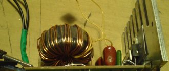
The most universal magnetic cores are W-shaped and cup-shaped armor cores. They can be used in any switching power supply, thanks to the ability to set a gap between the parts of the core. But, we are going to wind a pulse transformer for a push-pull half-bridge converter, the core of which does not need a gap and therefore a ring magnetic circuit is quite suitable. https://oldoctober.com/
For a ring core there is no need to make a frame and make a winding device. The only thing you have to do is make a simple shuttle.
The picture shows a ferrite magnetic core M2000NM.
The standard size of the ring magnetic core can be identified by the following parameters.
D is the outer diameter of the ring.
d – internal diameter of the ring.
H – ring height.
In reference books on ferrite magnetic cores, these dimensions are usually indicated in the following format: K D x d x H.
Obtaining initial data for simple calculation of a pulse transformer.
I remember when our power grids had not yet been privatized by foreigners, I built a switching power supply. The work dragged on until night. During the last tests, it suddenly turned out that the key transistors began to get very hot. It turned out that the network voltage jumped to 256 Volts at night!
Of course, 256 Volts is too much, but you shouldn’t rely on GOST 220 +5% –10% either. If you choose 220 Volts +10% as the maximum network voltage, then:
242 * 1.41 = 341.22V (we count the amplitude value).
341.22 – 0.8 * 2 ≈ 340V (subtract the drop on the rectifier).
We determine the approximate value of induction from the table.
Example: M2000NM – 0.39T.
The generation frequency of a self-excited converter depends on many factors, including the size of the load. If you choose 20-30 kHz, you are unlikely to make a big mistake.
Limit frequencies and induction values of widespread ferrites.
Manganese-zinc ferrites.
| Parameter | Ferrite grade | |||||
| 6000NM | 4000NM | 3000NM | 2000NM | 1500NM | 1000NM | |
| Cutoff frequency at tg δ ≤ 0.1, MHz | 0,005 | 0,1 | 0,2 | 0,45 | 0,6 | 1,0 |
| Magnetic induction B at Hm = 800 A/m, T | 0,35 | 0,36 | 0,38 | 0,39 | 0,35 | 0,35 |
Nickel-zinc ferrites.
| Parameter | Ferrite grade | |||||
| 200NN | 1000NN | 600NN | 400NN | 200NN | 100NN | |
| Cutoff frequency at tg δ ≤ 0.1, MHz | 0,02 | 0,4 | 1,2 | 2,0 | 3,0 | 30 |
| Magnetic induction B at Hm = 800 A/m, T | 0,25 | 0,32 | 0,31 | 0,23 | 0,17 | 0,44 |
Transformers
TransformersPower transformer circuit
Power transformers are usually designed to operate from electrical networks with two standard rated voltages: 127 and 220V. The network winding is usually called the primary winding, and the supply winding is called the secondary winding.
Shielding winding To reduce interference that can penetrate from the electrical network through the capacitance between the primary and secondary windings of the transformer into the device it powers, a screen (shielding winding) is usually made between these windings in the form of a layer of insulated wire. One of the ends of the shielding winding is connected to the body of the powered device, while the other remains free. The role of the screen can be performed by the incandescent winding of lamps if it is wound directly over the primary winding.
Autotransformers
An autotransformer is a transformer in which one of the windings is part of another winding. In autotransformers powering tube receivers and televisions, the primary winding is part of the winding from which the voltage is supplied to the valves (the case when the voltage must be greater than the mains voltage), or, conversely, it is part of the primary winding (when the voltage supplied to the valves must be less than the mains voltage). In the first case, the autotransformer is called a step-up, and in the second, a step-down. By your email. In the circuit, an autotransformer is similar to a choke with one or more taps.
In a step-up autotransformer, the mains voltage is applied to part of the winding turns and removed to the valves from the end of the winding. In a step-down autotransformer, voltage is applied to the ends of the winding and removed from part of it. The filament windings in an autotransformer are usually made isolated from the winding connected to the electrical network.
Application of autotransformers The rectifier autotransformer must be a step-up one if at the output of the rectifier filter it is necessary to obtain a constant voltage exceeding the mains voltage by 1.1 or a large number of times in the case of using a half-wave or bridge circuit with selenium valves; 1.25 or more times in the case of the same circuit, but with germanium or silicon valves; 2.2 or more times when using a voltage doubling circuit with selenium valves. 2.5 times or more when using a voltage doubling circuit with germanium or silicon valves. *If it is necessary to have lower rectified voltages (when using the same circuits in rectifiers), autotransformers must be step-down.
Advantage of autotransformers The advantage of an autotransformer over a transformer is that the dimensions and weight of the magnetic core of the autotransformer and the total number of turns of its windings are less than that of a transformer, and the efficiency is much higher. If the voltage removed from the common winding of the autotransformer differs from the network voltage by no more than 25%, and the power supplied to the load is more than 50-70 W, then the efficiency is autotransformer can practically be considered close to unity.
The main disadvantage of an autotransformer The main disadvantage of an autotransformer is that the device powered by it is connected to the electrical network. Therefore, none of the points in the device circuit can be grounded! Failure to comply with this condition may result in damage to the powered device by current passing from the electrical network to the ground or in a short circuit in the electrical network.
Magnetic cores
Material for magnetic cores: Magnetic cores (cores) that have transformers, autotransformers and chokes are made of special sheet or strip electrical steel with a thickness of 0.35-0.5 mm. These steels contain several percent silicon and up to 1% carbon. Silicon serves to increase the resistivity of steel, which reduces losses due to eddy currents and hysteresis and thereby increases efficiency. tr-ra. The steel grades used are E31, E32, E41, E42, E310, E320, E330. Where the first number indicates the average percentage of silicon content in it, the second characterizes the electromagnetic properties of steel: 1-steel with relatively large losses at a frequency of 50 Hz 2-steel with reduced losses 3-with very low losses 4-with “normal” losses at increased frequency (400Hz). The third digit of the steel grade "0" indicates the technological feature of its production - cold-rolled (textured) steel.
Types of magnetic cores Armored from W-shaped plates: The designation of an armored magnetic core made from W-shaped plates consists of the designation of the type of these plates, the multiplication sign and a number expressing the thickness of the magnetic core in millimeters. So, for example, a magnetic core made of plates of types Sh-25 and Ya-25, having a thickness of 40 mm, is designated Sh25x40.
Table 1
magnetic type
| density | power | turns | turns | |||||
| wires | current | per volt | per volt | |||||
| (core) | in the winding | |||||||
| a, mm x b, mm | Ah, mm | N, mm | s, mm | h, mm | J, A/mm2 | P, V*A | Nfirst | Nsecond. |
| W 3 x 4 | 12 | 10,5 | 3 | 7,5 | ||||
| W 3 x 6.3 | 12 | 10,5 | 3 | 7,5 | ||||
| W 4 x 5 | 16 | 14 | 4 | 10 | ||||
| W 4 x 8 | 16 | 14 | 4 | 10 | ||||
| W 5 x 6.3 | 20 | 18 | 5 | 12,5 | ||||
| W 5 x 10 | 20 | 18 | 5 | 12,5 | ||||
| W 6 x 8 | 24 | 21 | 6 | 15 | 6 | |||
| W 6 x 12.5 | 24 | 21 | 6 | 15 | 5 | |||
| W 10 x 10 | 40 | 35 | 10 | 25 | 4,8 | |||
| W 10 x 12.5 | 40 | 35 | 10 | 25 | 4,6 | |||
| W 10 x 16 | 40 | 35 | 10 | 25 | 4,4 | |||
| W 10 x 20 | 40 | 35 | 10 | 25 | 4,1 | |||
| USH 10 x 10 | 36 | 31 | 6,5 | 18 | 5 | |||
| USH 10 x15 | 36 | 31 | 6,5 | 18 | 4,5 | |||
| USH 10 x 20 | 36 | 31 | 6,5 | 18 | 4 | |||
| W 12 x 12 | 36 | 31 | 6 | 18 | 5,2 | |||
| W 12 x 12 | 42 | 42 | 9 | 30 | 5,0 | |||
| W 12 x 12 | 48 | 30 | 12 | 18 | 4,5 | |||
| W 12 x 12 | 48 | 42 | 12 | 30 | 4,2 | |||
| W 12 x 16 | 42 | 42 | 9 | 30 | 4,2 | |||
| W 12 x 16 | 48 | 30 | 12 | 18 | 4,3 | |||
| W 12 x 16 | 48 | 42 | 12 | 30 | 4 | |||
| W 12 x 20 | 48 | 30 | 12 | 18 | 4,1 | |||
| W 12 x 20 | 48 | 42 | 12 | 30 | 3,9 | |||
| W 12 x 25 | 48 | 30 | 12 | 18 | 4 | |||
| W 12 x 25 | 48 | 42 | 12 | 30 | 3,7 | |||
| USH 12 x 12 | 44 | 38 | 8 | 22 | 4,3 | |||
| USH 12 x 18 | 44 | 38 | 8 | 22 | 4,1 | |||
| USH 12 x 24 | 44 | 38 | 8 | 22 | 3,8 | |||
| W 16 x 16 | 48 | 40 | 8 | 24 | 4,7 | |||
| W 16 x 16 | 64 | 56 | 16 | 40 | 3,7 | |||
| W 16 x 20 | 64 | 40 | 16 | 24 | 3,8 | 11 | 13,1 | 17 |
| W 16 x 20 | 64 | 56 | 16 | 40 | 3,5 | 18 | 13,2 | 17 |
| W 16 x 24 | 48 | 40 | 8 | 24 | 4,2 | 7 | 11 | 13,5 |
| W 16 x 25 | 64 | 40 | 16 | 24 | 3,6 | 12 | 10,4 | 13 |
| W 16 x 25 | 64 | 56 | 16 | 40 | 3,4 | 22 | 10,5 | 12,7 |
| W 16 x 32 | 48 | 40 | 8 | 24 | 4,1 | 9 | 8,3 | 10 |
| W 16 x 32 | 64 | 40 | 16 | 24 | 3,5 | 15 | 8,3 | 10 |
| W 16 x 32 | 64 | 56 | 16 | 40 | 3,2 | 27 | 8,3 | 9,9 |
| W 16 x 40 | 64 | 40 | 16 | 24 | 3,3 | 18 | 6,7 | 7,8 |
| W 16 x 40 | 64 | 56 | 16 | 40 | 3,0 | 32 | 6,8 | 7,7 |
| USH 16 x 24 | 56 | 48 | 10 | 28 | 4,0 | 8 | 8,0 | 9,0 |
| W 18 x 18 | 54 | 45 | 9 | 27 | 5,2 | 10 | 15 | 20 |
| W 18 x 27 | 54 | 45 | 9 | 27 | 5,0 | 13 | 10,5 | 12 |
| W 18 x 36 | 54 | 45 | 9 | 27 | 4,1 | 17 | 8 | 9 |
| USH 19 x 19 | 67 | 58 | 12 | 33 | 3,7 | 12 | 10,8 | 13 |
| USH 19 x 28 | 67 | 58 | 12 | 33 | 3,5 | 17 | 6,5 | 7,3 |
| USH 19 x 38 | 67 | 58 | 12 | 33 | 3,2 | 22 | 5,0 | 5,6 |
| W 20 x 20 | 60 | 50 | 10 | 30 | 3,5 | 11 | 10 | 12,2 |
| W 20 x 20 | 80 | 50 | 20 | 30 | 3,5 | 18 | 10,6 | 13,2 |
| W 20 x 20 | 80 | 70 | 20 | 50 | 3,2 | 32 | 10,7 | 13,2 |
| W 20 x 25 | 80 | 50 | 20 | 30 | 3,4 | 22 | 8,6 | 10,5 |
| W 20 x 25 | 80 | 70 | 20 | 50 | 3,1 | 40 | 8,7 | 10,4 |
| W 20 x 27 | 65 | 65 | 12,5 | 45 | 4,3 | 25 | 8,2 | 10 |
| W 20 x 30 | 60 | 50 | 10 | 30 | 4,3 | 20 | 7,0 | 8,4 |
| W 20 x 32 | 80 | 50 | 20 | 30 | 3,2 | 27 | 6,8 | 8 |
| W 20 x 32 | 80 | 70 | 20 | 50 | 3,0 | 48 | 6,9 | 8 |
| W 20 x 40 | 60 | 50 | 10 | 30 | 4,0 | 25 | 5,5 | 6,4 |
| W 20 x 40 | 80 | 50 | 20 | 30 | 3,1 | 30 | 5,4 | 6,2 |
| W 20 x 40 | 80 | 70 | 20 | 50 | 2,9 | 55 | 5,5 | 6,2 |
| W 20 x 50 | 80 | 50 | 20 | 30 | 3,0 | 37 | 4,3 | 4,9 |
| W 20 x 50 | 80 | 70 | 20 | 50 | 2,7 | 70 | 4,3 | 4,9 |
| W 22 x 22 | 66 | 55 | 11 | 33 | 4,0 | 18 | 8,5 | 11 |
| W 22 x 33 | 66 | 55 | 11 | 33 | 3,6 | 27 | 6 | 7 |
| USH 22 x 22 | 67 | 78 | 14 | 39 | 3,1 | 20 | 8,0 | 9,3 |
| USH 22 x 33 | 67 | 78 | 14 | 39 | 2,9 | 28 | 5,4 | 6 |
| USH 22 x 44 | 67 | 78 | 14 | 39 | 2,6 | 34 | 4,1 | 4,3 |
| W 25 x 25 | 100 | 63 | 25 | 37,5 | 3,1 | 38 | 6,9 | 8,2 |
| W 25 x 25 | 100 | 88 | 25 | 62,5 | 2,9 | 70 | 6,9 | 8,1 |
| W 25 x 32 | 100 | 63 | 25 | 37,5 | 3,0 | 50 | 5,5 | 6,2 |
| W 25 x 32 | 100 | 88 | 25 | 62,5 | 2,8 | 90 | 5,5 | 6,3 |
| W 25 x 40 | 100 | 63 | 25 | 37,5 | 2,3 | 55 | 4,4 | 4,9 |
| W 25 x 40 | 100 | 88 | 25 | 82,5 | 2,7 | 100 | 4,4 | 4,9 |
| W 25 x 50 | 100 | 62,5 | 25 | 37,5 | 2,8 | 65 | 3,5 | 3,9 |
| W 25 x 50 | 100 | 87,5 | 25 | 62,5 | 2,6 | 130 | 3,5 | 3,8 |
| W 25 x 63 | 100 | 62,5 | 25 | 37,5 | 2,7 | 75 | 2,9 | 3,15 |
| W 25 x 63 | 100 | 87,5 | 25 | 62,5 | 2,5 | 155 | 2,9 | 3,1 |
| USH 26 x 26 | 94 | 81 | 17 | 47 | 3,5 | 70 | 4,9 | 5,5 |
| USH 26 x 39 | 94 | 81 | 17 | 47 | 3,2 | 85 | 3,4 | 3,8 |
| USH 26 x 52 | 94 | 81 | 17 | 47 | 2,7 | 100 | 2,7 | 3,0 |
| W 28 x 28 | 84 | 70 | 14 | 42 | 3,7 | 50 | 6,1 | 7,0 |
| W 28 x 42 | 84 | 70 | 14 | 42 | 3,2 | 70 | 4,05 | 4,5 |
| USH 30 x 30 | 106 | 91 | 19 | 53 | 2,8 | 100 | 4,2 | 4,6 |
| USH 30 x 45 | 106 | 91 | 19 | 53 | 2,6 | 130 | 3,1 | 3,3 |
| USH 30 x 60 | 106 | 91 | 19 | 53 | 2,4 | 170 | 2,4 | 2,5 |
| W 32 x 32 | 128 | 80 | 32 | 48 | 2,8 | 100 | 4,4 | 5,0 |
| W 32 x 32 | 128 | 112 | 32 | 80 | 2,6 | 140 | 4,5 | 5,0 |
| W 32 x 40 | 128 | 80 | 32 | 48 | 2,7 | 120 | 3,5 | 3,8 |
| W 32 x 40 | 128 | 112 | 32 | 80 | 2,5 | 210 | 3,6 | 3,8 |
| W 32 x 50 | 128 | 80 | 32 | 48 | 2,5 | 160 | 3,0 | 3,2 |
| W 32 x 50 | 128 | 112 | 32 | 80 | 2,4 | 250 | 3,0 | 3,2 |
| W 32 x 63 | 128 | 80 | 32 | 40 | 2,4 | 190 | 2,6 | 2,8 |
| W 32 x 63 | 128 | 112 | 32 | 80 | 2,3 | 290 | 2,5 | 2,7 |
| W 32 x 80 | 128 | 80 | 32 | 48 | 2,3 | 220 | 1,9 | 2,0 |
| W 32 x 80 | 128 | 112 | 32 | 80 | 2,2 | 330 | 2,0 | 2,1 |
| W 34 x 35 | 102 | 102 | 17 | 68 | 3,0 | 100 | 4,2 | 4,6 |
| W 34 x 52 | 102 | 102 | 17 | 68 | 2,7 | 160 | 2,5 | 2,7 |
| W 35 x 35 | 130 | 105 | 30 | 70 | 2,3 | 200 | 3,8 | 3,95 |
| W 35 x 45 | 130 | 105 | 30 | 70 | 2,1 | 250 | 2,8 | 3,0 |
| USH 35 x 35 | 123 | 106 | 22 | 61,5 | 2,6 | 160 | 3,3 | 3,5 |
| USH 35 x 52 | 123 | 106 | 22 | 61,5 | 2,4 | 200 | 2,3 | 2,4 |
| USH 35 x 70 | 123 | 106 | 22 | 61,5 | 2,2 | 220 | 1,7 | 1,8 |
| W 40 x 40 | 160 | 100 | 40 | 60 | 2,5 | 220 | 3 | 3,3 |
| W 40 x 40 | 160 | 140 | 40 | 100 | 2,3 | 350 | 3,05 | 3,3 |
| W 40 x 50 | 160 | 100 | 40 | 60 | 2,4 | 270 | 2,4 | 2,6 |
| W 40 x 50 | 160 | 140 | 40 | 100 | 2,2 | 400 | 2,45 | 2,6 |
| W 40 x 63 | 160 | 100 | 40 | 60 | 2,3 | 320 | 2 | 2,2 |
| W 40 x 63 | 160 | 140 | 40 | 100 | 2,1 | 480 | 2,05 | 2,2 |
| W 40 x 80 | 160 | 100 | 40 | 60 | 2,2 | 380 | 1,4 | 1,5 |
| W 40 x 80 | 160 | 140 | 40 | 100 | 2,0 | 600 | 1,46 | 1,5 |
| W 40 x 100 | 160 | 100 | 40 | 60 | 2,1 | 450 | 1,18 | 1,25 |
| W 40 x 100 | 160 | 140 | 40 | 100 | 1,9 | 730 | 1,2 | 1,25 |
| USH 40 x 40 | 144 | 124 | 26 | 72 | 2,3 | 270 | 2,6 | 2,8 |
| USH 40 x 60 | 144 | 124 | 26 | 72 | 2,2 | 400 | 1,8 | 1,9 |
| USH 40 x 80 | 144 | 124 | 26 | 72 | 2,1 | 500 | 1,4 | 1,5 |
Armor twisted from split tape: The designation of a twisted split armor magnetic core consists of the letters ШЛ (Ш-shaped, Tape) and two numbers separated by an x sign, the first of which indicates the width of the middle rod "a", the second the thickness of the magnetic core "b" in millimeters.
table 2
| magnetic type | density | power | turns | turns | ||||
| wires | current | per volt | per volt | |||||
| (core) | in the winding | |||||||
| a, mm x b, mm | Ah, mm | N, mm | s, mm | h, mm | J, A/mm2 | P, V*A | Nfirst | Nsecond. |
| SHL 10 x 10 | 40 | 35 | 10 | 25 | ||||
| WL 10 x 12.5 | 40 | 35 | 10 | 25 | ||||
| ШЛ 10 x 16 | 40 | 35 | 10 | 25 | ||||
| SHL 10 x 20 | 40 | 35 | 10 | 25 | ||||
| WL 12 x 12.5 | 48 | 42 | 12 | 30 | ||||
| WL 12 x 16 | 48 | 42 | 12 | 30 | ||||
| ШЛ 12 x 20 | 48 | 42 | 12 | 30 | ||||
| WL 12 x 25 | 48 | 42 | 12 | 30 | ||||
| WL 16 x 16 | 64 | 56 | 16 | 40 | ||||
| WL 16 x 20 | 64 | 56 | 16 | 40 | 2,8 | 16 | 10 | 12 |
| WL 16 x 25 | 64 | 56 | 16 | 40 | 2,7 | 24 | 8,6 | 10,2 |
| WL 16 x 32 | 64 | 56 | 16 | 40 | 2,5 | 35 | 6,5 | 7,4 |
| ШЛ 20 x 20 | 80 | 70 | 20 | 50 | 2,7 | 45 | 8,2 | 9,7 |
| WL 20 x 25 | 80 | 70 | 20 | 50 | 2,7 | 55 | 6,6 | 7,5 |
| WL 20 x 32 | 80 | 70 | 20 | 50 | 2,7 | 70 | 5,2 | 5,8 |
| WL 20 x 40 | 80 | 70 | 20 | 50 | 2,6 | 85 | 4,5 | 5,0 |
| WL 25 x 25 | 100 | 88 | 25 | 62 | 2,5 | 110 | 5,8 | 6,7 |
| WL 25 x 32 | 100 | 88 | 25 | 62 | 2,4 | 135 | 4,4 | 4,9 |
| WL 25 x 40 | 100 | 88 | 25 | 62 | 2,3 | 140 | 3,6 | 4,0 |
| WL 25 x 50 | 100 | 88 | 25 | 62 | 2,2 | 210 | 3,0 | 3,2 |
| WL 32 x 32 | 128 | 112 | 32 | 80 | 2,3 | 260 | 3,7 | 4,1 |
| WL 32 x 40 | 128 | 112 | 32 | 80 | 2,2 | 310 | 2,8 | 3,0 |
| WL 32 x 50 | 128 | 112 | 32 | 80 | 2,1 | 390 | 2,3 | 2,5 |
| WL 32 x 64 | 128 | 112 | 32 | 80 | 2,0 | 490 | 1,8 | 1,9 |
| WL 40 x 40 | 160 | 140 | 40 | 100 | 1,8 | 600 | 2,3 | 2,5 |
| WL 40 x 50 | 160 | 140 | 40 | 100 | 1,7 | 800 | 1,85 | 2,0 |
| WL 40 x 64 | 160 | 140 | 40 | 100 | 1,6 | 900 | 1,4 | 1,5 |
| WL 40 x 80 | 160 | 140 | 40 | 100 | 1,6 | 1100 | 1,13 | 1,2 |
Rod twisted from split tape: The designation of a twisted rod split magnetic core consists of the letters PL and three numbers, the first of which indicates the width of the rod “a”, the second the thickness of the magnetic core “b” and the third the height of the window “h”. All dimensions are in millimeters.
table 3
| magnetic type | density | power | turns | turns | ||||
| wires | current | per volt | per volt | |||||
| (core) | in the winding | |||||||
| a, mm x b, mm | Ah, mm | N, mm | s, mm | h, mm | J, A/mm2 | P, V*A | Nfirst | Nsecond. |
| PL 12.5 x 16-25 | 41 | 50 | 16 | 25 | 4,5 | 12 | 16 | 21 |
| PL 12.5 x 16-32 | 41 | 55 | 16 | 32 | 4,5 | 15 | 16 | 21 |
| PL 12.5 x 16-40 | 41 | 65 | 16 | 40 | 4,5 | 18 | 16 | 21 |
| PL 12.5 x 16-50 | 41 | 75 | 16 | 50 | 4,5 | 20 | 16 | 21 |
| PL 12.5 x 25-30 | 45 | 55 | 20 | 30 | 4,0 | 25 | 10 | 12,3 |
| PL 12.5 x 25-40 | 45 | 65 | 20 | 40 | 4,0 | 32 | 10 | 12,3 |
| PL 12.5 x 25-50 | 45 | 75 | 20 | 50 | 4,0 | 40 | 10 | 12,3 |
| PL 12.5 x 25-60 | 45 | 85 | 20 | 60 | 4,0 | 50 | 10 | 12,3 |
| PL 16 x 32-40 | 57 | 72 | 25 | 40 | 3,5 | 60 | 6 | 6,7 |
| PL 16 x 32-50 | 57 | 82 | 25 | 50 | 3,5 | 80 | 6 | 6,7 |
| PL 16 x 32-65 | 57 | 97 | 25 | 65 | 3,5 | 100 | 6 | 6,7 |
| PL 16 x 32-80 | 57 | 112 | 25 | 80 | 3,5 | 130 | 6 | 6,7 |
| PL 20 x 40-50 | 72 | 90 | 32 | 50 | 3,4 | 160 | 3,8 | 4,2 |
| PL 20 x 40-60 | 72 | 100 | 32 | 60 | 3,4 | 200 | 3,8 | 4,2 |
| PL 20 x 40-80 | 72 | 120 | 32 | 80 | 3,4 | 250 | 3,8 | 4,2 |
| PL 20 x 40-100 | 72 | 140 | 32 | 100 | 3,4 | 300 | 3,8 | 4,2 |
| PL 25 x 50-65 | 90 | 115 | 40 | 65 | 3,3 | 380 | 2,5 | 3,0 |
| PL 25 x 50-80 | 90 | 130 | 40 | 80 | 3,3 | 450 | 2,5 | 3,0 |
| PL 25 x 50-100 | 90 | 150 | 40 | 100 | 3,3 | 550 | 2,5 | 3,0 |
| PL 25 x 50-120 | 90 | 170 | 40 | 120 | 3,3 | 680 | 2,5 | 3,0 |
| PL 32 x 64-80 | 114 | 144 | 50 | 80 | 2,7 | 800 | 1,5 | 1,6 |
| PL 32 x 64-100 | 114 | 164 | 50 | 100 | 2,7 | 1000 | 1,5 | 1,6 |
| PL 32 x 64-130 | 114 | 194 | 50 | 130 | 2,7 | 1100 | 1,5 | 1,6 |
| PL 32 x 64-160 | 114 | 224 | 50 | 160 | 2,7 | 1500 | 1,5 | 1,6 |
Calculation and production of transformers, autotransformers.
The calculation of power transformers can be carried out in several versions, since it is possible to design transformers with the same parameters, with differing core sizes and winding data. In amateur radio conditions, when calculating a transformer, you often have to proceed from the presence of a magnetic circuit or plates for its assembly of one type or another.
The efficiency of a transformer is defined as the ratio of the sum of the powers removed from all its secondary windings to the power consumed by the primary winding from the electrical network. Fully loaded transformers have approximately the following efficiencies: power removed from the transformer = efficiency 10-20 W = 65-75% (0.65-0.75) 20-50 W = 70-80% (0.70-0.80) 50 -100 W = 75-85% (0.75-0.85) 100-200 W = 82-88% (0.82-0.88) 200-500 W = 85-90% (0.85-0.90) W = 90-95% (0.90- 0.95) The efficiency of underloaded transformers is less.
Typical (overall) power of a transformer (Рtr) Typical power of a transformer Рtr(V*A) is equal to half the sum of the total powers of the primary and all secondary windings of the transformer. The total power of each winding is the product of the effective value of its e. d.s. (V) to the effective value of the current flowing in it (A). The larger the useful cross-section of the core S(cm2) and the dimensions of its window c, h(cm), the greater the typical power of the transformer made on such a core. With a magnetic circuit of a given size, it is directly proportional to the amplitude of the magnetic induction Bm(T), the current density in the windings J(A/mm2) and its frequency Fc(Hz), efficiency. transformer ηtr and the coefficient of filling the core window with copper Bo:
Рtr=0.022×S×c×h×Вm×Fc×J×ηtr×Bo (general formula)
When calculating a transformer with an armored magnetic core made of plates of type Ш at Fc=50Hz and Рtr<1kW, the magnetic induction amplitude Bm=1.2T is usually taken. For a transformer made of USH type plates, Vm = 1.35T is allowed. For a tape twisted magnetic circuit Bm=1.6T. As a result of recalculation, the formula takes the following form:
Rtr=1.3×S×c×h×J×ηtr×Bo (armor magnet. Sh-plates)
Rtr=1.5×S×c×h×J×ηtr×Bo (armor magnet. USH plates)
Rtr=1.8×S×c×h×J×ηtr×Bo (twisted tape magnetic circuit)
If the transformer operates on a rectifier assembled using a bridge circuit or a voltage doubling circuit (as well as in the case of a filament transformer), then when the secondary windings are fully loaded, the power supplied to the primary winding is approximately equal to the overall (typical) power. In the case of a transformer operating on a rectifier assembled using a full-wave circuit or a single-half-wave circuit, the overall power of the transformer is greater than the power supplied from the network to its primary winding. The overall power of an autotransformer is, as a rule, less than the power it consumes from the mains. The smaller the ratio of the mains voltage to the removed voltage, the smaller it is. The use of an autotransformer is especially beneficial when it is necessary to obtain a voltage from it that is close in value to the supply voltage. In this case, the overall power of the autotransformer is significantly less than the overall power of a transformer for the same purpose. The required power of transformers and autotransformers for rectifiers can be calculated using the formulas given in table 4. Formulas for calculating the parameters of transformers and autotransformers. table 4
For the case of a semiconductor rectifier using selenium valves, if they are fully used in terms of current, larger numerical coefficients should be used in the calculations in the formulas, and for the case of a rectifier using germanium or silicon valves (and for selenium valves when they are underloaded in current), smaller numerical coefficients should be used. When calculating the overall power of an autotransformer intended to operate from electrical networks with different voltages, the lowest network voltage in the case of a step-up autotransformer and the highest in the case of a step-down one must be substituted into the formula. If the autotransformer operates as a step-down at a network voltage of 220V, and as a step-up at lower network voltages, then you need to calculate the overall power for both the highest and the lowest rated network voltage, and select the largest from the two values obtained. The larger the useful cross-sectional area of the magnetic core Sst and the area of its window So, the greater the overall power of the transformer (autotransformer) that can be manufactured on this magnetic core. The overall power of a transformer (autotransformer) also depends on the temperature to which it can be heated, and the higher the current density J in the windings, the stronger the latter. For transformers or autotransformers with windings made of wires of the PEL, PBO, PBD, PShD, PELSHO and PELSHD brands, the heating temperature should not exceed 100*C, and with windings made of wires with heat-resistant insulation of the PEV and PET brands = 125*C. The temperature to which a transformer or autotransformer is heated is equal to the sum of the ambient air temperatures and overheating, i.e., the overheating temperature characterizes the excess of the transformer temperature above the ambient air temperature during prolonged operation of the load. Selecting a magnetic core. The magnetic core must be selected so that its overall power, calculated using the appropriate formula given in Table 4, does not exceed the maximum overall power (taking into account permissible overheating). It is recommended to choose a magnetic core of such a size that the required overall power is 10-20% less than the maximum permissible. It is most advisable to use magnetic cores with a ratio of thickness “b” to rod width “a” in the range of 1.5-2.0 (for example: Ш20х30, УШ30х60). With large b/a ratios, tight winding of the windings becomes difficult, since the turns on the sides (larger sides) do not lie tightly enough (bulge). Magnetic cores with a b/a ratio = 1 (for example: W20x20) and less should be used only in cases where when the dimensions of the transformer are significant. Winding a transformer or autotransformer with a magnetic core made of USh-type plates consumes approximately 10% less wire than a transformer with the same overall power, but with a magnetic core made of Sh-type plates. Winding a transformer with a twisted magnetic core requires 15-20% less wire. than a transformer of the same overall power, but with a magnetic core assembled from stamped plates. At the same time, the weight of the twisted magnetic circuit is approximately two times less.
Calculation of power transformer, method No. 1. (simpler and less accurate)
1. Knowing the dimensions of the magnetic circuit, using the above tables we determine its approximate overall power (data); if we need to know its exact power, we use it to calculate the formula. 2. We wind the primary (network ~210, ~220, ~230) winding. We look at the graph to see what maximum current can flow through it.
According to the nomogram indicated below, the choice of dia. wires” we determine what diameter wire we need. If a wire with the calculated diameter is not available, use a wire with the nearest larger standard diameter. You can also use other methods to determine the required wire diameter: *The cross-sectional area of the wire is calculated using the formula: S=Irev/J (S-cross-sectional area of the wire, Irev-current of the primary winding, J-current density). After this, using the wire tables, find the wire diameters corresponding to the calculated cross-sectional areas S. *The wire diameter can also be calculated using the formula: d=1.13Ö Irev/J
3. How many turns we need to wind, we determine from the above tables Nfirst. multiply by the required mains voltage (~220V). 4. When winding the winding between the rows, insulating pads made of impregnated paper are used, but it is better to use a pad that is used in high-voltage non-electrolytic capacitors! Depending on the diameter of the wire (mm), choose the thickness of the gasket (mm): <0.2=0.03-0.05 0.21-1.0=0.06-0.08 1.04-1.74=0.1-0.2 1.81-2.2=0.2-0.3 >2.2=>0.3 At voltage windings up to 20V, it is recommended to make gaskets every three rows, and for high voltages - through each row of wire. If the voltage exceeds 50V, the gaskets must be double-layered. 5. If necessary, make a shielding winding. 6. Based on the voltage we need, the load current and the power of the selected magnetic circuit, we wind the secondary winding. We determine the number of turns by multiplying the voltage (V) we need by Nsecond (number of turns per volt) indicated in tables 1,2,3. To find out what diameter of wire we need for winding at the maximum load current we have chosen, we need to use the nomogram for “selecting the diameter of the winding wire”:
Using tables 1,2,3, we look at the current density in the magnetic circuit used. We substitute it into the nomogram and get the diameter of the winding wire.
Calculation of power transformer, method No. 2.
It is required to design a transformer for a semiconductor rectifier using germanium or silicon valves (diodes) using a full-wave bridge circuit with the following data: Up=1000V, Ip=0.46A (2 pcs GU50, with Ia. max.=0.23a for one GU50) Un= 12.6V, In=1.52A (2 pieces GU50). 1. According to the formula in Table 4, we determine the overall power of the transformer: Рт = 1.6 UpIп + 1.2 UnIn, where 1.6 is a numerical coefficient (for circuits with silicon or german diodes). We get: Рт=1.6х1000х0.46+1.2х12.6х1.52=759W 2. According to Table 2, select the magnetic circuit ШЛ 40х50 (Рт=800W). 3. According to the same table, the network winding should have ~220V x 1.85 (turns per 1 volt) = 407 turns, the current that will flow in it will be determined from the graph and it will be equal to about 3.5A. According to Table 2, the current density is 1.7 A/mm2, therefore, this winding requires a wire with a cross-section of at least S=Irev/J=3.5/1.7=2.05 mm2. The diameter of the wire can also be calculated using the formula: d=1.13Ö Irev/J=1.6mm. 4. We determine the number of turns of the filament winding according to Table 2, it is equal to 12.6V x 2 turns per 1 volt = 25 turns. Since In=1.52A and J=1.7A/mm2, it requires a wire with a cross-section of at least S=Irev/J=1.52/1.7=0.9 mm2. The wire diameter can also be calculated using the formula: d=1.13Ö Irev/J=1.07mm. 5. According to the formula in Table 4 for the bridge circuit Ud=0.8Up=0.8x1000=800V and Id=1.8Ip=1.8x0.46=0.87A. We determine the number of turns of the secondary winding according to Table 2, it is equal to 800V x 2 turns per 1 volt = 1600 turns. Wire cross-section not less than S=Irev/J=0.87/1.7=0.5 mm2. The diameter of the wire can also be calculated using the formula: d=1.13Ö Irev/J=0.8mm.
Calculation of power autotransformer.
It is required to design an autotransformer for a rectifier with the following data: Up=220V, Iп=0.07A, Un=6.3V, In=3A, Uс=127 and 220V. The rectifier is supposed to be made according to a circuit with doubling the voltage on diodes of type D7. 1. According to the formula in Table 4 for such a circuit Ud=0.4Up=0.4x270=110v. Consequently, the autotransformer will work as a step-down transformer in all cases. 2. According to the formula in Table 4, we determine the overall power for the voltage doubling circuit: Pat=1.6(1-0.4Up/Uc)UpIp+1.2UnIn=1.6(1-110/220)270x0.07 +1.2x6.3x3=39VA 3. According to Table 1, select a magnetic core Ш25х40 with dimensions 100х62.5 mm. According to the same table, the total number of winding turns for Uс=220V should be 970, and the tap for Uс=127V should be made from the 560th turn. 4. The number of turns of section Ia is determined from the column “turns per volt, Nprimary.” according to the required voltage 110V we get 485 turns 5. From the graph we determine I127=0.46a and I220=0.26a. According to the formulas Ib = I127 and Ic = I220, the currents of sections Ib and Ic are equal: Ib = I127 = 0.46a and Ic = I220 = 0.26a. According to the formula in Table 4: Id=3.6Ip=3.6x0.07=0.25a and according to the formula Ia=I127-Id, the current of section Ia is equal to: Ia=I127-Id=0.46-0.25=0 ,21a. 6. According to Table 1 J=2.3a/mm2. Therefore, for section Ia a wire with a cross-section of at least 0.2/2.3=0.087mm2 is required, for section Ib with a cross-section of 0.46/2.3=0.2mm2 and for section Ib with a cross-section of 0.26/2.3=0.113 mm2. We select wires with the closest standard diameters: for section Ia with a diameter of 0.35 mm (S = 0.087 mm2); for section Ib with a diameter of 0.51 mm (S = 0.204 mm2); for section Ib with a diameter of 0.38 mm (S = 0.113 mm2). In order to reduce the range of wires, sections Ia and Ib can be wound with wire with a diameter of 0.38 mm. 7. The 6.3V filament winding according to Table 1 should have 31 turns. Since In=3a, with J=2.3mm2 its wire should have S=3/2.3=1.3mm2. We select a wire with a diameter of 1.3 mm (S = 1.33 mm2).
Where did the information come from: IAG3 Radio Amateur Designer's Handbook, 1973. Calculation and production of transformers and autotransformers. Date of publication of the article: 12/19/05.
How to calculate the number of turns of the primary winding?
We enter the initial data obtained in the previous paragraphs into the calculator form and obtain the number of turns of the primary winding. By changing the size of the ring, the grade of ferrite and the generation frequency of the converter, you can change the number of turns of the primary winding.
It should be noted that this is a very, very simplified calculation of a pulse transformer.
But, the properties of our wonderful self-excited power supply are such that the converter itself adapts to the parameters of the transformer and the load size by changing the generation frequency. So, as the load increases and the transformer tries to enter saturation, the generation frequency increases and the operation returns to normal. Minor errors in our calculations are compensated in the same way. I tried to change the number of turns of the same transformer by more than one and a half times, which is reflected in the examples below, but I could not detect any significant changes in the operation of the power supply, except for a change in the generation frequency.
Features of winding pulse transformers.
Winding pulse transformers, and especially transformers on ring and toroidal magnetic cores, has some features.
The fact is that if any winding of the transformer is not distributed evenly enough around the perimeter of the magnetic circuit, then individual sections of the magnetic circuit may become saturated, which can lead to a significant reduction in the power of the power supply and even lead to its failure.
It would seem that you can simply calculate the distance between the individual turns of the coil so that the turns of the winding fit exactly into one or several layers. But, in practice, winding such a winding is difficult and tedious.
We are trying to wind a “lazy winding”. And in this case, the easiest way is to wind a single-layer winding “turn to turn”.
What is needed for this?
It is necessary to select a wire of such a diameter that it fits “turn to turn”, in one layer, into the window of the existing ring core, and even so that the number of turns of the primary winding does not differ much from the calculated one.
If the number of turns obtained in the calculator does not differ by more than 10-20% from the number obtained in the formula for calculating the laying, then you can safely wind the winding without counting the turns.
True, for such winding, most likely, you will need to choose a magnetic circuit with a slightly higher overall power, which I already advised above.
1 – ring core.
3 – winding turns.
D is the diameter by which you can calculate the perimeter occupied by the turns of the winding.
The picture shows that when winding “turn to turn”, the calculated perimeter will be much smaller than the internal diameter of the ferrite ring. This is due to both the diameter of the wire itself and the thickness of the gasket.
In fact, the actual perimeter that will be filled with wire will be even smaller. This is due to the fact that the winding wire does not adhere to the inner surface of the ring, forming some gap. Moreover, there is a direct relationship between the diameter of the wire and the size of this gap.
You should not increase the tension of the wire when winding in order to reduce this gap, since this can damage the insulation and the wire itself.
Using the empirical formula below, you can calculate the number of turns based on the diameter of the existing wire and the diameter of the core window.
The maximum calculation error is approximately –5% + 10% and depends on the density of the wire.
w = π(D – 10S – 4d) / d , where:
w – number of turns of the primary winding,
π – 3,1416,
D – internal diameter of the ring magnetic core,
S – thickness of the insulating gasket,
d – diameter of wire with insulation,
/ - fractional line.
How to measure the diameter of a wire and determine the thickness of the insulation is described here.
Several examples of calculations of real transformers.
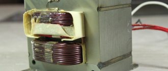
Design features of the W-shaped transformer plate
Any transformer contains two main parts: a closed core and copper windings. The core, in turn, consists of plates, which are created using special electrical steel. The thickness of the core plates directly affects the operating frequency of the transformer: the thinner the part, the greater the parameter.
A transformer with an W-shaped core is also called an armored one. The main conditions under which such plates are used:
- frequency no more than 8 kHz;
- maximum power 150V*A.
The W-shaped plate increases the leakage flux due to bifurcation of the magnetic flux. The position of the windings on the middle rod of the core protects them from interference and mechanical stress.
Parts for high-frequency transformers are preferably made from three main materials: permalloy, alsifer and ferrite. The latter has a wide range of working particles, which explains the use of ferrite to create pulse transformers.
The description of the transformer magnetic circuit gives the parameters of the set of plates. For example, if it is indicated that it is necessary to take iron Ш15Х10, this means that:
- The width of the middle part of the plate should be 15 mm.
- The thickness of the resulting stack of W-shaped plates is 10 mm.
The main advantage of a core assembled from plates is its resistance to mechanical stress. This allows you to assemble a magnetic circuit even from fragile materials. The disadvantage of the design is increased sensitivity to low-frequency magnetic fields.
When assembling the core, jumpers are added to the W-shaped plate.
To minimize the gap formed between the jumper and the plate, the magnetic circuit is assembled “over the roof”.