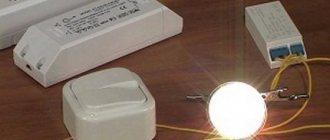
Due to the significant advantages of halogen light bulbs over incandescent lamps in terms of service life and efficiency, they are increasingly replacing outdated models of lighting equipment. However, most ordinary people are faced with the problem of electrical installation work associated with halogen lamps due to the peculiarities of their operation. Since the connection of halogen devices must be done through a special converter. This type of device is a transformer for halogen lamps, which has a special purpose in the power supply circuit.
Why does a halogen transformer need a transformer?
In an effort to improve the performance characteristics of certain electrical devices, there is a constant improvement of both production processes and operating principles. Empirically, it was determined that halogen lamps will last much longer if they are powered from a reduced voltage. The optimal rating is considered to be 6 V, 12 V and 24 V, which cannot be directly obtained from a household network.
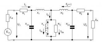
Of all the methods for converting alternating voltage, it is the step-down transformer that has taken root in practice. It implements the principle of interaction of the electromagnetic field of the high voltage winding with the turns on the low side. As a result, a voltage of one magnitude is converted into a reduced voltage on the output winding. The advantage of this method is galvanic isolation, which ensures safety when operating halogen lighting devices.
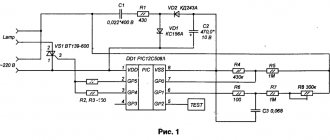
↑ Improvement of Tasсhibra - a capacitor in the PIC instead of a resistor!
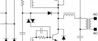
You can avoid heating resistor R5 by replacing it with... a capacitor.
In this case, the PIC circuit certainly acquires some resonant properties, but no deterioration in the operation of the power supply is manifested. Moreover, a capacitor installed instead of a resistor heats up significantly less than the replaced resistor. Thus, the frequency with a 220nF capacitor installed increased to 86.5 kHz (without load) and amounted to 88.1 kHz when operating with a load.
The startup and operation of the converter remained as stable as in the case of using a resistor in the PIC circuit. Note that the potential power of the power supply at such a frequency increases to 220 W (minimum). Transformer power: values are approximate, with certain assumptions, but not exaggerated.
Unfortunately, I did not have the opportunity to test a power supply with a large load current, but I believe that the description of the experiments performed is enough to draw the attention of many to such simple power converter circuits, worthy of use in a wide variety of designs .
I apologize in advance for possible inaccuracies, omissions and errors. I'll correct myself in answering your questions.
Calculation and selection
To select a specific model of step-down transformer for halogen lamps, you need to take into account two main parameters: power and output voltage, the input voltage is taken as a constant. They can be checked in the passport or on the case, as shown in the figure:
Rice. 1. Determination of transformer parameters
In addition, it is necessary to take into account the features of two fundamentally different types of devices - electromagnetic and electronic converters. To determine the prospects for using each of them in your case, first, let’s look at the advantages of both.
Electromagnetic
The advantages of electromagnetic electrical machines include:
- Relatively lower cost;
- Simple design;
- A high degree of reliability of such a device.
But along with these advantages, they also have disadvantages in comparison with electronic reduction devices - the presence of noise during operation and rather large dimensions, which limits the scope of application. Sensitivity to surges and transient processes in the network has also been noted.
Electronic
Electronic transformers differ in their operating principle, since they involve semiconductor conversion of electrical energy. In addition, they are equipped with a soft start device, control of operating temperatures, overload and other protections.
Their advantages also include:
- Relatively low noise load produced during operation;
- Compactness – the size of this transformer for halogen lamps is much smaller;
- Adaptation to idle operation.
By introducing a variety of technologies, pulse converters provide longer service life for halogen light bulbs than winding transformers. However, they also have some disadvantages: relatively high cost, lower reliability and minimum power restrictions.
Selecting the physical parameters of the transformer
Having decided on the type of transformer for halogen lamps, you need to select the desired potential difference and rating. The input voltage of each of them is 220V, however, for connecting halogen lighting devices, the rating can vary by 6, 12 or 24 Volts. Therefore, the voltage must be selected based on the characteristics of the lamps that you will use.
The amount of power is selected on the principle that it is no less than that required to power electric lamps. When choosing a transformer rating, the output power is deliberately increased to provide an electrical safety margin. Otherwise, overheating, complete shutdown, or even failure may occur.
To calculate, you need to take into account the following parameters:
- Power of one lamp;
- Number of lamps connected to the transformer;
- Connection diagram.
For example, consider the option of connecting nine electric lamps with a power of 10 W. Based on this, you will need 9 × 10 = 90 W, and taking into account the safety margin of 90 + 9 = 99 W, accordingly, you need to choose electromagnetic or electronic devices of at least 100 W. After this, a lighting scheme using halogen lamps is drawn up.
Disadvantages of ET models offered on the market
Despite the economical and well-developed design, electric power supplies have a number of disadvantages, which are usually classified as:
- lack of special overload protection in the simplest Chinese models;
- the resulting need for mandatory modification of the scheme;
- Many market samples do not have an input filter device, which forces them to add a smoothing electrolytic capacitor (it is placed after the “powerful” choke).
The listed disadvantages usually include the “hard” operating mode of high-voltage transistors connected according to a key circuit.
In the event of an accidental output short circuit (SC), these elements simply “burn out,” which leads to the need for an urgent update of the entire electronic module. Often, the rectifier based on semiconductor diodes also breaks down and also needs to be replaced.
It is not advisable to repair ET, since it costs almost a penny. It is much easier and cheaper to purchase a new module and modify it to suit your needs.
Connection options and diagrams
It should be noted right away that it will be more practical if in the connection diagrams you use a parallel connection of lamps, so that voltage is supplied to each lighting device from a low-voltage pulsed source. The first option for powering halogen lamps will involve equally parallel connection of all lighting devices to one transformer.
Rice. 2. Parallel circuit
As you can see in the diagram, power from the external network is supplied to the input of the transformer, which is designated as Input, and a reduced voltage of 12V is removed from the output terminals (Output). Next, the output of each of the terminals is connected to points A and B in the diagram, from which they are connected to the contacts of the lamps, as shown in the figure. In this case, each lamp has independent power supply and if any of them burns out, the others will continue to light, but they will all depend on the serviceability of the source.
There is also a scheme for connecting several groups from different pulse blocks. As an example, we will consider a circuit of two devices and four low-voltage halogen lamps for each of them.
Rice. 3. Connection scheme for several groups
As you can see in the figure, two transformers are used here, between which the power consumption from the lamps is divided. The advantage of this scheme is the ability to independently turn on each group of lighting fixtures. The switch is designed for two keys, separately for each converter, but you can use one for both groups at once. This method allows you to take a transformer for halogen lamps with half the power for each group, but it also requires high costs for the implementation of the circuit.
Bonding versus clamping
The choice between bonding and clamping depends largely on the manufacturer's capabilities and preferences, but there are also application-specific requirements that may determine one or the other as more desirable.
- Advantages of gluing Easy to automate production.
- Homogeneity of the core cross-section (saturation).
- Low assembly height (clamping arc does not protrude).
- Smaller PCB cutout dimensions (integrated version).
- Fixation of the core on the printed circuit board (no rattling or noise).
- Cleanliness of the assembly process.
Recommendations and tips
When installing a transformer for halogen lamps, you need to take into account a number of nuances that will help you avoid unpleasant mistakes and their consequences:
- when connecting the high and low sides, do not confuse the pins, otherwise the unit will have to be thrown away - Input input for the high side is 220V, Output is the output for the low side, may be abbreviated In and Out or PRI and SEC, respectively;
Rice. 4. Example of input and output designation on a transformer
- transformers become very hot during operation, so halogen lamps should be located at least 200 mm from them;
- if the transformer is located in a niche, then the volume of space for one device must be at least 12 liters, otherwise it will overheat at rated loads;
- to avoid fire, the transformer must be installed on a plate made of non-flammable material;
- The dimmer does not combine well with pulsed current, so to adjust the brightness of the light flux, choose special transformer models that indicate the possibility of dimming, an example of such a designation is shown in the figure:
Rice. 5. Dimmable transformer
Application
The first application of planar transformers was power conversion. Accordingly, mid- and high-frequency powerful ferrites were used. The inductance of the line filter choke can be increased by replacing the powerful ferrite with a material with high magnetic permeability. In pulsed signal transmission, a wideband transformer located between the pulsed generator IC and the cable provides decoupling and impedance matching. In the case of an S- or T-interface, it must also be ferrite with high magnetic permeability. 3E6 high permeability ferrite cores have been added to the FERROXCUBE product range. A list of applications where the use of planar technology can provide benefits is given below.
