TL431 is an adjustable parallel voltage regulator. Otherwise, it can be called a “controlled programmable zener diode”. It is intended for use as a reference voltage block in various variations of power supply circuits, and can also serve as a substitute for Zener diodes in various circuits. Despite the considerable age of the microcircuit - almost 50 years - it remains popular today. All thanks to its size, stability and ease of connection. It has good characteristics that allow it to be used on both a hobby and industrial scale. Among other things, another advantage of this chip is the low noise level at its output.
The TL431 was first introduced to the world by Texas Instruments back in 1977. Over all this time, the technical production process has been significantly improved, and therefore the accuracy of the characteristics in comparison with those indicated in the datasheet. Since then, this chip has become an integral part of a large variety of manufactured switching power supplies.
TL431 circuit
Let's consider the circuit, which is in the official datasheet of the manufacturer Texas Instruments.
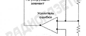
The scheme is quite simple. It shows a very ordinary operational amplifier (looks like a triangle in the picture), which is connected to a transistor at the output.
How does TL431 work?
Everything here is elementary. The input to the operational amplifier is a 2.5V reference voltage source, which is connected to the input. The pin, code-named REF, and the collector and emitter of the transistor are connected to the power supply pins of the amplifier. And safety is ensured by a protective diode, which will preserve and protect the microcircuit from polarity reversal.
In order for the output transistor to open, you need to apply a signal to the REF input, the voltage of which will be slightly greater than the reference one. Since an excess of a couple of millivolts is enough, we can safely assume that we are supplying a voltage that is equal to the reference one. In this case, the output from the op-amp sends voltage to the base of the transistor, and it opens.
It turns out that this microcircuit is like a field-effect transistor. It continuously compares the input voltage with the reference voltage, and when the voltage at the input is higher, it opens.
Especially for those who are especially curious, the TL431 datasheet also contains an image of a detailed diagram:
As you can see, even in the expanded diagram shown, the TL431 device does not evoke a feeling of fear.
Device and principle of operation
In appearance, the device resembles an ordinary transistor. However, despite the three pins, the tl431a integrated circuit (IC) includes:
- operational amplifier (op-amp);
- reference (reference) voltage source UREF;
- transistor switched on at the output.
The tl431 IC monitors such a parameter as voltage and is called a controlled zener diode.
Attention! The reference (reference) voltage (UREF) is necessary not to power the circuits of the microcircuit, but in order to, based on the value of this voltage, stabilize the output of the IC.
Controlled zener diode device
If we draw an analogy with a transistor, then a parallel voltage stabilizer (SV) made using bipolar triodes also has three terminals:
- “base” – control input (R0);
- “collector” – cathode (C);
- “emitter” – anode (A).
When the CH operates, a positive potential is applied to the control input (R0) and the anode (A). The current IKA flowing through the cathode-anode circuit is represented by a stabilized output signal.
Important! The op-amp within the IC compares the UREF value with the incoming U and, based on this, performs stabilization. In this IC, UREF is 2.5 V and is generated by the built-in source.
In other words, the transistor installed at the output of the op-amp will open when the voltage supplied to the input is equal to or slightly exceeds UREF.
Schematic diagram
As follows from the diagram, a voltage divider made of resistive elements is located on electrode R. Using external dividers, it is actually possible to organize stabilization in the range Uin = 2…36 V. In this case, the maximum current can reach 100 mA.
Interesting. If you short-circuit the first and third pins and do not use a divider, then the stabilization voltage of such a controlled stabilizer will be equal to 2.5 V.
Types of TL431
The TL431 is produced in various housing variations. Depending on the type of installation, you can choose the one that suits your project. For through-hole and surface mounting: TO-92, and for surface mounting: SOT-23, SOT-25, SOT-89 and SOP-8.
For prototyping and simple homemade projects without using printed circuit boards, the TO92 is the most convenient option, since it can be used both in conjunction with a breadboard and with surface mounting.
TL431 connection
Regardless of the type of case, the microcircuit has 3 contacts. And in cases with a large number of legs, the remainder is not used or duplicates the main 3. Here you can see the pinout of all TL431 variants.
The minimum connection diagram consists of only one resistor. At the output of this circuit, the voltage will be equal to the reference - 2.5V.
What is the TL431 chip?
This microcircuit, developed in the 70s of the twentieth century, is often called a “regulated zener diode”, and in the diagram it is designated as a zener diode with two classical terminals - anode and cathode. There is also a third conclusion, the purpose of which will be discussed later. In appearance, the microassembly does not resemble a zener diode at all. It is produced like a regular microcircuit, in several housing options. Initially, variants were manufactured only for boards with holes (true hole), but with the development of SMD technologies, TL431 began to be “packaged” in surface-mount packages, including popular SOTs with different numbers of pins. The minimum number of legs required for operation is 3. Some cases contain a larger number of leads. The extra legs are either not connected anywhere or are duplicated.
Circuits using TL431
The chip can be used in many different power supply designs. These can be either regulated power supplies or battery chargers. Let's look at a few basic, typical schemes that can be modernized, and on the basis of which you can create your own ideas and creations.
Voltage stabilizer on TL431 (2.5-36V, 100mA)
This circuit allows you to replace an ordinary zener diode. You can change the output voltage by changing the resistance of resistors R1 and R2. To calculate the resistance, we recommend using the formula below:
Voltage stabilizer with increased maximum current (2.5-36V)
The maximum output current of the TL431 is 100mA. However, if your project requires a higher output current, then we advise you to use a transistor: then the maximum current will depend on its characteristics. The formula for calculating resistor resistance remains the same.
Similar circuits are often used with other ICs. Unfortunately, most of them simply cannot pass high current, so to solve this problem, a control transistor comes into play. In this case, the maximum current is limited by its properties. The main task here is the correct selection of the transistor for the control voltage at its base.
Laboratory power supply on TL431 with protection
This circuit is an adjustable power supply that is capable of delivering up to 30W. And besides this, it has built-in overload protection. If the current begins to exceed the permissible value on transistor T2, then the voltage supply to the LBP will stop, which will be signaled by a lit LED.
Do not forget to use cooling in the form of a radiator, because components will quickly heat up during peak loads, and over time, with frequent overheating, they will fail.
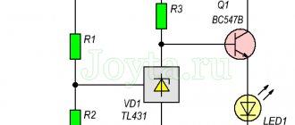
Current stabilizer on TL431 (LED driver)
Most often, current stabilizers are used to power LEDs and LED strips. The circuit here is elementary - you only need a couple of resistors and one transistor.
Voltage indicator
The circuit may be needed when you need to ensure that the voltage does not go beyond the upper and lower limits. These limits are set by the resistance of the resistors, according to the formula given below.
This circuit can be upgraded by adding tweeters or other sound devices. This way you will definitely not be able to miss a signal about an incorrect voltage.
Delay timer on TL431
A universal microcircuit on which it is possible to implement even a delay timer circuit. All you need is a couple of resistors and a capacitor. Their values must be calculated using the formula to obtain the required delay time (the formula is given below).
This circuit is possible due to the very low input current (4 μA). When the main contact closes, the transistor begins to charge. After reaching 2.5V, it opens, and current, assisted by an optocoupler LED (optocoupler), begins to flow, causing a short circuit in the external circuit.
Charger for lithium batteries on TL431 and LM317
This simplest circuit allows you to properly charge lithium batteries. This charging uses TL431 as the voltage reference and LM317 as the current source. The device charges batteries using the CC CV method, which means, as everyone knows, Constant Current, Constant Voltage.
The input voltage for this circuit is 9-20V. First, the battery is charged with a constant current, which can be changed by changing the resistance of resistor R5. After the battery reaches a voltage of about 4.2V, it begins to charge with constant voltage.
Please note that it is very important to configure the device before use: without load, you need to adjust the variable resistor RV1 so that the output voltage is 4.2 Volts.
Diagram for 15 V blocks
The zener diode TL431 switching circuit through a 15 V block is carried out using a single-stage converter. In turn, the modulator is suitable with a capacitance of 5 pF. Resistors are used exclusively of the selective type. If we consider modifications with triggers, then the threshold voltage parameter does not exceed 3 W. The stabilization accuracy is around 3%. Filters for the system are suitable for both open and closed types.
It is also important to note that an expander may be installed in the circuit. Today, models are produced mainly of the switched type
For modifications with transceivers, the current conductivity does not exceed 4 microns. In this case, the sensitivity of the zener diode fluctuates around 30 mV. The output impedance reaches approximately 80 Ohms.
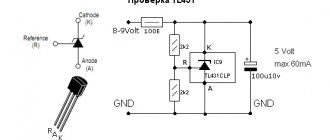
How to check TL431
Since this is not a single radio component, but a whole circuit enclosed in a small package, we cannot test it with just a multimeter, because it only contains 10 transistors, not to mention the other components. Checking the resistance between the pins will not provide any useful information, since reference values vary from batch to batch and from manufacturer to manufacturer.
Therefore, as with testing most microcircuits, it is necessary to assemble a simple circuit using it. The following diagram could serve as such:
When 12V is supplied to the input, the output should be 5V, and when S1 is closed, the reference voltage of the TL431 microcircuit should go to the output - 2.5V. You can choose your own values. It is important that they comply with the formula:
If all the values are correct, then the chip is working and can be used in the project. If you assemble a small stand with such a circuit on a breadboard, you will be able to test a large number of TL431 and similar microcircuits in a pipeline.
Specifications
Let's consider the maximum permissible characteristics of the TL431 chip. If they are exceeded during operation, the device will fail. Long-term operation of the device with parameters close to the maximum is also dangerous for it. The meanings of these parameters are presented below:
- the highest possible voltage between the anode and cathode is 37 V;
- range of currents flowing through the cathode for a long time – from -100 to +150 mA;
- current range at the input (control electrode) of the device – from -0.05 to +10 mA;
- The maximum power dissipation depends on the housing type:
- SOT-89 – 0.8 W;
- TO-92 – 0.78 W;
- SO-8 – 0.75 W;
- SOT-23 – 0.33 W;
- SOT-25 – 0.5 W.
- operating temperature range – from -25 to +85С;
- maximum permissible crystal temperature – +150 °C;
- The temperature range at which the product can be stored is -65 to +150 °C.
In the technical documentation, manufacturers provide a range of recommended performance characteristics. The voltage at the cathode VKA can vary from a minimum equal to the control VREF to a maximum of 36 V. The cathode current must be in the range from 1 to 100 mA.
When designing a new device, you should also pay attention to the electrical characteristics. The measurement was carried out at a temperature TC= 25°C. Other testing parameters are given in the “Measurement modes” column.
| Options | Measurement Modes | Designation | min | typ | max | Unit change |
| Control voltage | VKA=VREF,IKA=10 mA | VREF | 2,455 | 2,495 | 2,535 | IN |
| The amount of control voltage deviation with temperature change | VKA=VREF,IKA=10 mA, Ta = 0°C to +85°C | VDEV | 9,0 | 20 | mV | |
| Change in voltage at the control electrode depending on the change in voltage at the cathode | IKA=10 mA ΔVKA=10V~VREF ΔVKA=36V~10V | ΔVREF ΔVKA | -1,0 -0,5 | -2,7 -2,0 | mV/V mV/V | |
| Current through the control electrode | IKA=10 mA | IREF | 1,5 | 4 | µA | |
| Deviation of control (reference) current with temperature change | IKA=10 mA | ΔIREF ΔT | 0,4 | 1,2 | µA | |
| Minimum control current through the cathode, | VKA=VREF | IKA(MIN) | 0,3 | 0,5 | mA | |
| Current through the cathode with a closed junction | VKA=36V, VREF=0 | IKA(OFF) | 0,05 | 1,0 | µA | |
| Dynamic resistance | VKA=VREF, f≤1.0 kHz IKA=1 to 100 mA | ZKA | 0,15 | 0,5 | Ohm |
Application of TL431
This chip can be used in various power devices of varying power. TL431 is used in the production of power supplies, LBPs, voltage and current stabilizers, and other things.
This chip can serve as a conventional comparator, but thanks to the internal reference power supply, circuits using the TL431 in this way are greatly simplified. In this case, you can use it to create a circuit for a thermostat and other devices for reading signals from analog sensors. It can also serve as a voltage indicator. Including sound.
But most often it is used as a reference power source in conjunction with other microcircuits, since it produces it very stably. There are many circuits where the TL431 is used in conjunction with the LM317, another popular adjustable stabilizer.
Independent chip-based devices
This chip is used in power supplies for televisions and computers. However, on its basis it is possible to create independent electrical circuits, some of which are:
- current stabilizer;
- sound indicator.
Current stabilizer
The current stabilizer is one of the simplest circuits that can be implemented on the tl 341 microcircuit. It consists of the following elements:
- power supply;
- resistance R 1, connected via a common point to the + power line;
- shunt resistance R 2 k - power line;
- a transistor whose emitter is connected to the - line through resistor R2, the collector to the output - line, and the base through a common point to the cathode of the microcircuit;
- tl 341 microcircuit, whose anode is connected to the - line using a common current, and the ref pin is connected to the emitter circuit of the transistor also using a common point.
Sound indicator
The sound indicator based on tl 341 is a simple circuit shown in Figure 5.
Such a sound indicator can be used to monitor the water level in a container. The sensor is an electronic circuit in a housing with two output electrodes made of stainless steel, one of which is located 20 mm higher than the other.
At the moment the sensor leads come into contact with water, the resistance decreases and tl 341 transitions to linear mode through resistors R 1 and R 2. This contributes to the appearance of auto-generation at the resonant frequency and the formation of an audio signal.
Analogs TL431
Since the microcircuit has gained great popularity, it is now not difficult to find its analogues. If you are looking for analogues from domestic manufacturers, then here is a list for you:
- KR142EN19
- KR142EN19A
- K1156ER5T
The most complete analogues are:
- IR943N
- TL432
- LM431
You can also use the following to replace Tl431:
- KA431AZ
- KIA431
- HA17431VP
- IR9431N
- AME431BxxxxBZ
- AS431A1D
- LM431BCM
- HA17431A, KIA431
- APL1431
For most of these options, the scheme will not need to be changed. But it’s worth checking the datasheet of each of them to be sure that the pinout is the same as the TL431.
Safe Operation of the TL431
During operation, it is necessary to comply with the environmental parameters described by the manufacturer. This is necessary not only for longer component life, but also for predictable behavior. The table below shows the performance of the TL431 at 25°C.
The element must not be overloaded; its maximum input voltage is 36V.
It is best that the load current is at least 5mA, otherwise the microcircuit may operate unstable and unpredictably.
Manufacturers TL431
Due to its incredible popularity, the TL431 is produced by almost all of the largest enterprises that specialize in the production of microcircuits. However, not all of them are sold in the CIS; many are sold only abroad. Among those companies whose products come to us:
- Texas Instruments
- ONS
- STM
- Nexperia
- HTC
- NXP Semiconductors
Other manufacturers of these products whose products are not available from us: Hotchip Technology, Calogic, Motorola, HIKE Electronics, Fairchild Semiconductor.