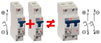
A differential automatic power supply switch is a modular device that combines two electrical devices in its design: an on/off automatic switch and an RCD (residual current device). The device is capable of protecting electrical wiring from overloads and short circuits (short circuits), as well as disconnecting the network when current leaks through damaged insulation or when a person touches live parts of electrical appliances. Consequently, a difavtomat performs two functions: it protects wiring and electrical appliances from overloads, and a person from electric shock.
The versatility of the device gives it certain advantages over separately installed automatic circuit breakers and RCDs. Physically, a differential circuit breaker takes up less space and costs less than two protective modules, a circuit breaker + RCD. But this electrical product also has disadvantages: if one of the component parts of the device fails, the entire automatic device will have to be completely replaced, and this is somewhat more expensive. But the advantages of a differential machine, of course, offset this insignificant drawback!
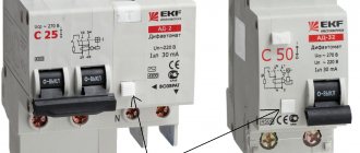
All models of difavtomats, three-phase and single-phase, have special flags in their design that indicate the reason for the device’s operation - power overload or leakage current. This is very important when determining the circumstances of an emergency shutdown. Differential circuit breakers are installed in electrical distribution panels, most often on special DIN rails. In this article, we will sequentially consider the following issues: the operating principle and connection diagrams of the differential machine, as well as how to properly connect the differential machine to the network.
Design and operating principle of differential switch
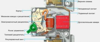
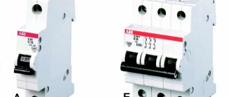
All cases of difavtomats are made using non-electrically conductive materials. A latch is installed on the rear wall of the module for fastening to a DIN rail. Installation of the device is carried out in the same way as a simple circuit breaker or RCD. In single-phase networks with a voltage of 220 V, two-pole modules with four contacts are installed for input and output of phase and neutral conductors. In three-phase networks with a voltage of 380 V, four-pole automatic circuit breakers with eight contacts are used to connect the input and output conductors of three phases and the neutral.
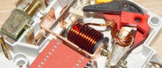
Protection of the power supply circuits in the differential circuit breaker from short circuits and power overloads is performed by a built-in automatic shutdown unit, consisting of a release mechanism for electrical contact pads, which is triggered to turn off the power supply when the rated load current is exceeded. In addition, the difavtomat module is equipped with a special rail for manual on/off. To protect people and animals from electric shock, the second block of the difavtomat is designed, which includes a control differential transformer with an electromagnetic device shutdown coil, which instantly de-energizes the network in the event of a dangerous difference in values between the input and output current values.
Differential circuit breakers are successfully used in both three-phase and single-phase AC transmission lines. These electrical products significantly increase the operating safety of various household appliances and electrical appliances. But in order for the difavtomat to perform its protective functions, it must be correctly connected to the network, observing the norms of the PUE (electrical installation rules). Below we will look at connection diagrams for differential circuit breakers.
Options
When installing a difavtomat, three main parameters should be taken into account:
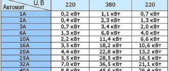
- Supply voltage and number of phases – 220V or 380V, 1 phase or 3.
- Operation current. This parameter is similar to that of the circuit breaker.
- Leakage current. Everything here is similar to an RCD.
There are a few more parameters that not everyone is familiar with:
- Rated breaking capacity. Short circuit current that the device can withstand without malfunctioning.
- Response time of differential protection.
- Current limiting class. Shows the time it takes to extinguish the electric arc during a short circuit.
- The type of electromagnetic release on which the excess of the operating current compared to the rated one depends.
Type of electromagnetic release
The electromagnetic release in the automatic circuit breaker is designed to instantly open the circuit when the rated current is exceeded by a specified number of times. The following types are common:
- B – the operating current exceeds the rated current by 3-5 times.
- C – operation current exceeds the rated current by 5-10 times.
- D – operation current exceeds the rated current by 10-20 times.
Leakage current (disconnecting differential current) and its class
The sensitivity threshold of the differential transformer determines the leakage current, which triggers the protection. The most widespread are differential transformers with a sensitivity of 10 and 30 mA.
In addition to the numerical value of the leakage current, the shape is important. In accordance with this, the following classes of protection devices are distinguished:
- AC – sinusoidal leakage current is controlled.
- A - in addition to sinusoidal, a pulsating constant is taken into account, which is important when protecting digital electronic equipment.
- B – a smoothed constant is added to the listed currents.
- S – shutdown time delay – 200-300 ms.
- G – time delay – 60-80 ms.
Rated breaking capacity and current limiting class
This parameter characterizes the short circuit current that the contact group of the circuit breaker is able to withstand without damage during the shutdown time. The higher the value of the parameter, the greater the likelihood that after eliminating the damage in the network, the difavtomat will remain operational. A typical range of values is:
- 3000 A;
- 4500 A - together with the first value, is practically not used today;
- 6000 A is a frequently used value;
- 10000 A - suitable for places close to the power substation, but has a high cost.
The current limiting class characterizes the shutdown speed when a critical current flows. The switch-off time (speed) includes the arc extinguishing time between the breaking contacts. Less time, i.e. higher shutdown speed, guarantees greater safety. There are three classes: from first to third.
Electronic or electromechanical
Based on internal equipment, electromechanical and electronic devices are distinguished. Electromechanical automatic machines are considered more reliable and do not require external power to operate.
Electronic devices have more stable parameters, but for normal operation they require stable power at the input.
Selective type operating principle
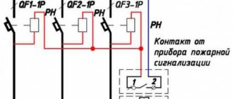
In branched electrical networks, a two-level protection system is used.
At the first level, a differential automatic machine is installed that controls the load line completely. On the second, difavtomats control each selected circuit separately.
To prevent the simultaneous operation of protection devices of both levels, the first differential circuit breaker must have selectivity, which is determined by the shutdown delay time. For these purposes, machines of classes S or G are used.
Connection diagrams for difavtomats
The connection diagram of a differential circuit breaker depends on many conditions: the number of phases in the network, the presence or absence of grounding, the installation location of the differential circuit breaker and the characteristics of the room it is intended to protect. All these factors influence the choice of device connection diagram, and besides, the device itself can have a different design - two-pole or four-pole, as well as different technical characteristics. Below we will look at the most common diagrams for connecting a difavtomat to electrical networks.
- A simple connection diagram to a single-phase line with grounding. This option provides for the protection of the entire internal electrical wiring of the room with one input difautomatic device installed in the distribution board after the electricity meter. This scheme is easy to implement, but has a rather serious drawback. In the event of an emergency, the differential circuit breaker de-energizes all wiring completely. In this case, it is much more difficult to find the reason for the protection to operate than with other circuits for connecting difavtomats.
- Reliable connection diagram to a single-phase line with grounding. This difavtomat connection diagram is an improved version. It implements the principle of dividing electricity consumers into groups, where a separate differential switch is installed for each of them. The reliability of such a connection is certainly higher, and it is much easier to determine where a current leak or overload in the network has occurred than with the first option. The disadvantage of this connection of the difavtomat is the increase in material costs for purchasing additional devices.
- Connection diagram for a differential circuit breaker without grounding. This difavtomat connection diagram is used in old multi-storey buildings, private households and dachas, where a two-wire network without a grounding conductor is used. Such a connection can protect electrical appliances from overloads and short circuits. The lack of grounding increases the risk of electric shock to people, but in this case the differential circuit breaker is able to provide safety to a person by instantly de-energizing the network when a leakage current occurs through his body. Still, you should replace the electrical wiring with a new one, with a full grounding contact.
- Selective circuit diagram for connecting a difavtomat for a single-phase network. Reliable protection of household appliances and people in a single-phase network can be ensured using a selective automatic circuit breaker (marked S) in combination with conventional devices. The selective circuit is designed to connect several consumers. In the event of an emergency, a bunch of difavtomats will disconnect from the network only the room where the overload or current leakage occurred. There will be no disconnection from the network for other electricity consumers.
- Connection diagram for a three-phase network with a neutral conductor. To implement this circuit, a three-phase differential circuit breaker should be used. The connection diagram itself is not much different from the previous ones, if you do not take into account the fact that four current-carrying wires will be used at the input and output of the device. This option for connecting a difavtomat is most often used in cottages, garages and workshops where powerful machinery and equipment are used.
Any circuit with a differential circuit breaker is excellent protection against short circuits and overloads for household electrical appliances and the power supply line itself, as well as for humans from electric shock. An optimally selected connection diagram is capable of performing all its functions, of course, if the installation of the difavtomat is carried out correctly.
Conclusions and useful video on the topic
You will learn from the following videos what difficulties you may encounter when connecting protective devices.
Testing a two-level selective and non-selective scheme:
Internal structure of the difavtomat:
Analysis of various circuit diagrams for connecting difavtomats (3 parts):
Connecting a protective differential circuit breaker is a simple process. The main condition for quick installation is strict adherence to the recommended electrical diagrams. In this case, self-installation of protective devices will be possible the first time, and the RCBOs themselves will reliably serve for many years.
Would you like to share your own experience in connecting a differential machine? Do you know the subtleties of installing the device that are not given in the article? Please write comments, ask questions, post photos in the block below.
Installation of a differential circuit breaker in a distribution board
After selecting the connection diagram for the difavtomat, it is necessary to install it correctly and integrate it into the electrical network. Most often, the differential switch is mounted in the distribution panel where the electricity meter is installed, but sometimes a set of modular devices is installed in an additional distribution box, which is located indoors. In both cases, the rules and steps for connecting the device are the same. Let's consider this process using the example of installing a difavtomat in an additional electrical panel:
- The installation of a differential circuit breaker should begin by checking the integrity of its housing, since any damage will lead to unstable operation of this device;
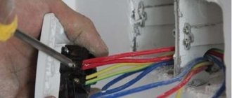
- after that, we turn off the electricity at the site and check the absence of voltage in the network using an indicator screwdriver or a multimeter, and if everything is in order, we proceed directly to the installation of the automatic machine;
- we install the differential circuit breaker on a special DIN rail and secure it with a latch located on the back side of the differential circuit breaker;
- we remove the insulation from all connected wires, using a special tool during this operation that is not capable of damaging the metal conductors of the wires;
- We connect all current-carrying conductors in accordance with the previously selected connection diagram for the difavtomat, with the incoming wires being inserted from the top and the outgoing wires from the bottom;
- at the last stage, we turn on the power supply and check the functionality of the differential circuit breaker using available methods.
The technology for installing a difavtomat, at first glance, is very simple! But even such work can be completed with errors, which we will discuss below.
Traditional mistakes when installing a difavtomat
If the installation of a differential circuit breaker is carried out in violation of the rules and regulations, then problems will inevitably arise, such as false triggering of the differential circuit breaker or even complete failure of the entire device or its individual parts. The culprits of such negative events may be the following main errors that occur when connecting the difavtomat to the network.
- The neutral conductor at the output of the difavtomat is connected directly to the neutral contacts of other modular devices located in the electrical distribution panel. Such connection is strictly prohibited! With such incorrect installation, false alarms of the device will certainly occur, which arise due to different values of electric current in the neutral conductors of each module.
- The phase (L) and neutral conductors (N) included in the difavtomat are mistakenly inserted from the bottom of the device body. Such installation can completely disable the module. This mistake is often made by inattentive people. The circuit diagram drawn on the front panel of the differential switch itself clearly states that the incoming wires should be connected to the top contacts and nothing else.
- The zero of the difavtomat is connected to ground, which is typical for old houses where a single-phase two-wire power supply line is used. Such a connection of a differential circuit breaker is also unacceptable, since this installation option will cause constant false alarms of the protection.
- The neutral conductor (N) is brought into an apartment, house or other building directly, bypassing the automatic circuit breaker. When connecting the device, the phases are mixed up with zero. These two errors will lead to false operation of the device or its failure, with the need for subsequent replacement.
Above, we examined the main mistakes when installing difavtomats, which a person can make as a result of inattention or poor professional training. Any of them is unacceptable, as it leads to the fact that the device is not able to perform its main function - protecting people from electric shock, and protecting electrical wiring and household appliances from overloads and short circuits!
Popular RCBO connection errors
After installation, the difavtomat may not turn on or immediately knock out. Mistakes by novice masters lead to similar phenomena:
- Combining the protective zero (ground) and the working zero (neutral) in a separate area. The device does not turn on, the handle at the top does not lock.
- Using load zero for low-level machines not from the output, but from the zero bus. The switches are brought into the operating position, but are turned off when the load is applied.
- The zero at the output is not output to the load, but returns to the bus. The load zero is taken from the bus. The switches are in the working position; after pressing the test key, the difavtomat turns off.
- The cable from the zero bus goes to the lower terminal with the letter N, the wire does not go to the load. When the switches are active, the “Test” button does not work; operation is possible when voltage is applied.
- The neutrals of two devices are mixed up. Both are activated, the test button works. When the load is applied, both automatic switches are switched off.
- Connection of zeros from two machines on any site. The switches are raised, but when you press the test key for one device or apply a load, both are turned off.
To resolve any problems, you will need to reconnect.
Independently connecting a protective differential circuit breaker will not be difficult for a person with skills who follows the diagram. A reminder and a list of basic connection errors will help you avoid device malfunctions.