Hello dear readers of the site. We continue to get acquainted with semiconductor diodes. In the previous part of the article, we figured out the operating principle of the diode, examined its current-voltage characteristic and found out what pn
transition.
In this part we will look at the design
and
operation of rectifier diodes
.
A rectifier diode is a semiconductor diode designed to convert
AC to DC. However, this is far from a complete area of application of rectifier diodes: they are widely used in control and switching circuits, in voltage multiplication circuits, in all high-current circuits where there are no strict requirements for the time and frequency parameters of the electrical signal.
General characteristics of rectifier diodes.
Depending on the value of the maximum permissible forward current, rectifier diodes are divided into small
,
medium
and
high
power:
low power
designed for direct current rectification up to 300mA;
average power
– from 300mA to 10A;
high power
- more than 10A.
According to the type of material used, they are divided into germanium
and
silicon
, but today
silicon
rectifier diodes are most widely used due to their physical properties.
Silicon diodes, compared to germanium diodes, have many times lower reverse currents at the same voltage, which makes it possible to obtain diodes with a very high permissible reverse voltage, which can reach 1000 - 1500V, whereas for germanium diodes it is in the range of 100 - 400V .
The performance of silicon diodes remains at temperatures from -60 to +(125 - 150)º C, and germanium diodes - only from -60 to +(70 - 85)º C. This is due to the fact that at temperatures above 85º C the formation of electronic hole pairs becomes so significant that there is a sharp increase in the reverse current and the efficiency of the rectifier decreases.
DIODE MARKING
A diode usually refers to vacuum or semiconductor devices that pass alternating electric current in only one direction and have two contacts for inclusion in an electrical circuit. One-way conductivity of a diode is its main property. Diodes come in low, medium, high and ultra-high frequencies. In addition, they have different power dissipation: low, medium and high.
DIODE DESIGNATION (NEW SYSTEM)
The FIRST element (number or letter) indicates the source semiconductor material:
- G or 1 - germanium or its compounds;
- K or 2 - silicon or its compounds;
- A or 3 - gallium arsenide;
- And or 4 - indium compounds.
The SECOND element (letter) denotes a subclass of diodes:
- D - rectifier and pulse diodes;
- C - rectifying posts and blocks;
- B - varicaps;
- B - Gunn diodes;
- I - tunnel diodes;
- A - ultra-high-frequency diodes;
- C - zener diodes;
- G - noise generators;
- L - emitting optoelectronic devices;
- O - optocouplers.
The THIRD element (number) indicates the main functionality of the device. For subclass D (diodes):
- 1 - rectifier diodes with a constant or average forward current value of no more than 0.3 A;
- 2 - rectifier diodes with a constant or average forward current value of more than 0.3 A, but not more than 10 A;
- 4 - pulse diodes with a reverse resistance recovery time of more than 500 ns;
- 5 - pulse diodes with a recovery time of more than 150 ns, but not more than 500 ns;
- 6 - pulse diodes with recovery time 30...150 ns;
- 7 - pulse diodes with recovery time 5...30 ns;
- 8 - pulse diodes with recovery time 1...5 ns;
- 9 - pulsed diodes with an effective lifetime of minority charge carriers of less than 1 ns.
The FOURTH element (number) indicates the serial number of the development. The FIFTH element (letter) conditionally determines the classification of devices.
DIODE DESIGNATION (OLD SYSTEM)
The FIRST element (letter) is the name, D is the diode. The SECOND element (number) indicates the type of diode:
- 1…100 – point germanium;
- 101...200 - dot silicon;
- 201...300 - planar silicon;
- 801...900 - zener diodes;
- 901…950 - varicaps;
- 1001…1100 - rectifying columns.
The THIRD element (letter) indicates the type of device. This element may be missing if there are no diode varieties.
For example, the KD202A diode is deciphered as follows: K - silicon diode, D - rectifier diode, 202 - purpose and development number, A - variety.
COLOR MARKING OF DIODES
For some types of diodes, color markings in the form of dots and stripes are used. Marking strips (rings, marks) can be located both on the anode side and on the cathode side. If there are several marking strips, then you should pay attention to their thickness and to the marks that determine the polarity of the terminals. If the color and type of markings match for different standard ratings, you should pay attention to the color of the case.
The following types of diodes are distinguished:
- The D9 family is marked with one or two colored rings in the anode area.
- KD102 diodes in the anode area are indicated by a colored dot. The case is transparent.
- KD103 have a color body that complements the dot, with the exception of 2D103A, which is indicated by a white dot in the anode area.
- The KD226, 243 families are marked with a cathode region ring. No other marks are provided.
- KD247 family - two colored rings in the cathode area.
- KD410 diodes are indicated by a dot in the anode area.
Table for determining the standard rating of domestic diodes by color marking:
Imported diodes have a different designation system; when choosing an analogue, use special correspondence tables. Marking is carried out in accordance with JEDEC (USA) and PRO ELECTRON (Europe) standards.
DESIGNATION OF DIODES IN THE DIAGRAM
The symbol for a diode is a triangle (symbol of the anode), together with the electrical connection line crossing it, forming something like an arrow indicating the direction of conduction. The line perpendicular to this arrow symbolizes the cathode.
The letter code of the diodes is VD. This code designates not only individual diodes, but also entire groups, for example, rectifier columns. On the basis of the basic symbol, graphic symbols for semiconductor diodes with special properties are also constructed.
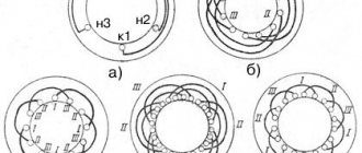
Manufacturing technology and design of rectifier diodes.
The design of rectifier diodes consists of one plate of a semiconductor crystal, in the volume of which two regions of different conductivity are created, therefore such diodes are called planar
.
The technology for manufacturing such diodes is as follows: onto the surface of a semiconductor crystal with electrical conductivity n
-type
aluminum
,
indium
or
boron
, and
phosphorus
is melted p .
Under the influence of high temperature, these substances are firmly fused with the semiconductor crystal. In this case, the atoms of these substances penetrate (diffuse) into the thickness of the crystal, forming in it a region with a predominance of electronic
or
hole
electrical conductivity.
In this way, a semiconductor device is obtained with two regions of different types of electrical conductivity - and a p-n
junction between them. Most common planar silicon and germanium diodes are made in this way.
To protect against external influences and ensure reliable heat dissipation, a crystal with pn
the transition is mounted in the housing.
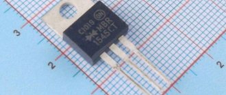
Low-power
diodes are manufactured in a plastic case with flexible external leads,
medium-power
are made in a metal-glass case with rigid external leads, and
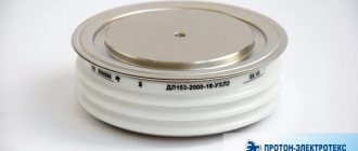
high-power
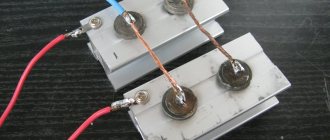
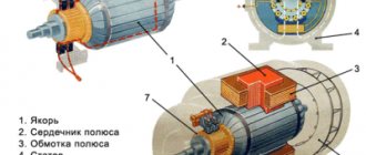
are made in a metal-glass or metal-ceramic case, i.e. with glass or ceramic insulator. An example of germanium (low power) and silicon (medium power) rectifier diodes is shown in the figure below.
Silicon or germanium crystals (3
) with
p-n
junction (
4
) are soldered to the crystal holder (
2
), which is also the base of the housing.
A housing ( 7
) with a glass insulator (
6
) is welded to the crystal holder, through which the lead of one of the electrodes (
5
) passes.
Low-power diodes, which have relatively small dimensions and weight, have flexible leads (1
) with the help of which they are mounted in circuits.
For medium-power and high-power diodes designed for significant currents, the terminals ( 1
) are much more powerful. The lower part of such diodes is a massive heat sink base with a screw and a flat outer surface, designed to provide reliable thermal contact with an external heat sink (radiator).
Electrical parameters of rectifier diodes.
Each type of diode has its own working
and
maximum permissible
parameters according to which they are selected for operation in a particular scheme:
Iobr
– constant reverse current, µA;
Upr
– constant forward voltage, V;
Ipr max
– maximum permissible forward current, A;
Urev max
– maximum permissible reverse voltage, V;
Р max
– maximum permissible power dissipated by the diode;
Operating frequency
, kHz;
Operating temperature
, C.
Not all diode parameters are given here, but, as a rule, if you need to find a replacement, then these parameters are sufficient.
Circuit of a simple AC rectifier using one diode.
Let us analyze the operation diagram of the simplest rectifier, which is shown in the figure:
variable to the input of the rectifier
voltage, in which
positive
half-cycles are highlighted in red and
negative
are highlighted in blue.
Rн
to the output of the rectifier
VD
will perform the function of the rectifying element .
With positive
half cycles of voltage supplied to the anode of the diode, the diode
opens
.
current
Ipr
through the diode, and therefore through the load ( Rн
), powered by the rectifier
wave is shown in red in the right graph).
For negative
Half cycles of voltage supplied to the anode of the diode, the diode
closes
diode
current Irev
will flow throughout the entire circuit .
Here, the diode seems to cut off the negative
half-wave of the alternating current (in the right graph, such a half-wave is shown by a blue dotted line).
As a result, it turns out that through the load ( Rн
), connected to the network through a diode (
VD
), the flow is no longer alternating, since this current flows only in positive half-cycles, and
the pulsating
current is a current of one direction. This is AC rectification.
But this voltage can only power a low-power load that is powered by an AC mains and does not have any special power requirements, for example, an incandescent lamp. Voltage will only pass through the lamp during positive half-waves (pulses), so the lamp will flicker faintly at a frequency of 50 Hz. However, due to thermal inertia, the filament will not have time to cool down in the intervals between pulses, and therefore the flickering will be faintly noticeable.
If we power a receiver or power amplifier with this voltage, then in the loudspeaker or speakers we will hear a low-pitched hum with a frequency of 50 Hz, called AC hum
. This will happen because the pulsating current, passing through the load, creates a pulsating voltage in it, which is the source of the background.
This drawback can be partially eliminated if in parallel
connect a high-capacity filtering
electrolytic capacitor
(Cf) to the load.
Charging by current pulses during positive half-cycles, the capacitor ( Cph
) during negative half-cycles
it is discharged
through the load (
Rн
).
If the capacitor is of sufficiently large capacity, then during the time between current pulses it will not have time to be completely discharged, which means that the current will be continuously maintained at the load ( Rн
) both during positive and negative half-cycles. The current maintained by charging the capacitor is shown in the right graph as a solid wavy red line.
But even with such a somewhat smoothed current, it is also impossible to power a receiver or amplifier because they will “phon”, since the ripple level ( Upulse
) is still very noticeable.
half
of the alternating current waves
is usefully used the input
voltage is lost on it and therefore such rectification of alternating current is called
half-wave
, and rectifiers are
half-wave rectifiers
.
These shortcomings are eliminated in rectifiers using a diode bridge
.
Basic selection options
Rated current . The first and one of the most important characteristics that should be chosen based on the expected load on the network. The higher the rated current of the device, the higher its shutdown threshold will be. But you should not choose a machine with a “reserve” for this characteristic, otherwise it may not cope with its main task - protecting the network from overloads. In addition, the higher the value of this parameter for a device, the higher its price. The appropriate rated current can be calculated using the following formula I= P/U , where:
I (A) – the desired value;
P (Watt) – total power consumption. To calculate it, you need to add up the power of all electrical appliances in the house and multiply the resulting number by a factor of 0.7. Power consumption is always indicated in the electrical equipment data sheet, as well as on its body, usually on the back on a special sticker.
U (V) – network voltage.
The resulting value must be rounded to the nearest standard series. The main ones are circuit breakers with a rated current of 6A, 10A, 16A, 25A, 32A, 40A, 50A, 63A.
Class (type of trip) - this parameter is indicated by a Latin letter and shows the number of times the rated current is exceeded at which the circuit breaker trips.
- A – 2-3 is designed for long-distance wiring in any buildings.
- B – 3-5 suitable for residential buildings;
- C – 5-10 for places where a lot of equipment is connected to the network, for example, for an industrial enterprise or a private workshop.
- D – 10-20 is similar to C.
Number of poles - this characteristic is related to the phases of the network. For single-phase, single-pole (in TN-C, TT power networks) and two-pole (in IT power networks) switches are used, and for three-phase – three-pole (in TN-C, TT, IT power networks) and four-pole (in TN-S power networks).
We hope that this article will help you in choosing a suitable machine. But to install this equipment, we advise you to contact a qualified specialist so that the installation is carried out correctly and problems do not arise later.
Below you will find the correct answer to Aircraft brand 2 letters Crossword Clue, if you need more help finishing your crossword continue your navigation and try our search function.