Help Me Understand the Scheme (Nc Designation)
Translation from light-faced into Russian. ====================================== Address of the Congress of Intelligentsia to the citizens of Russia. We, Russian(?) citizens, express solidarity with the open letter of more than 200 independent regional deputies directed against the adoption of amendments to the Constitution initiated by President V.V. Putin. -We are against the Russian Federation ensuring the protection of its sovereignty and territorial integrity. -We are against the Russian Federation, united by a thousand-year history, preserving the memory of its ancestors who passed on to us the ideals and faith in God, as well as continuity in the development of the Russian state, recognizing the historically established state unity. -We are against the Russian Federation honoring the memory of the defenders of the Fatherland and ensuring the protection of historical truth. -We, the undersigned, oppose children being the most important priority of Russian state policy. We do not want the State to create conditions conducive to the comprehensive spiritual, moral, intellectual and physical development of children, instilling in them patriotism, citizenship and respect for elders. -We oppose the idea that the state language of the Russian Federation throughout its entire territory should be Russian as the language of the state-forming people included in the multinational union of equal peoples of the Russian Federation. -We do not want republics to have the right to establish their own official languages. -We do not believe that the Russian Federation should guarantee the rights of indigenous peoples in accordance with generally accepted principles and norms of international law and international treaties of the Russian Federation. -Moreover, we oppose the protection of the cultural identity of all peoples and ethnic communities of the Russian Federation, and especially any guarantees for the preservation of ethnocultural and linguistic diversity. -In our deep and handshake conviction, the Russian Federation should not provide support to compatriots living abroad in the exercise of their rights, ensuring the protection of their interests and preserving the all-Russian cultural identity. -The capital of the Russian Federation should under no circumstances be the city of Moscow! -The Russian Federation should under no circumstances respect the work of citizens and ensure the protection of their rights. It is completely unacceptable for the state to guarantee a minimum wage of no less than the subsistence level of the working population as a whole in the Russian Federation! -No social insurance, especially targeted social support for citizens and indexation of social benefits and other social payments! I\We will fight with all our might to prevent such a mockery of democratic values under any circumstances! -We call on the leaders of democratic political and public organizations to unite with the goal of peacefully forcing the authorities to hold parliamentary elections in 2021 on the terms of political pluralism and democracy. We invite everyone who shares this position to choose one of two solutions: vote against the amendments to the Constitution or ignore the voting procedure itself. “Firing list” Lev Ponomarev, human rights activist Valery Borshchev, human rights activist Lyudmila Ulitskaya, writer Svetlana Gannushkina, human rights activist Andrei Smirnov, film director Oleg Basilashvili, People's Artist of the USSR Liya Akhedzhakova, People's Artist of the Russian Federation Andrei Makarevich, musician, poet Vladimir Mirzoev, director Natalya Fateeva, people's RSFSR artist Leonid Gozman, psychologist, publicist Dmitry Bykov, writer Viktor Shenderovich, writer Harry Bardin, animator director Lev Timofeev, writer Zoya Svetova, journalist Alexey Malobrodsky, theater producer Joseph Raikhelgauz, director, People's Artist of Russia Grigory Mikhnov-Vaitenko, sacred minister Yuri Bogomolov, film critic and television critic.. And other persons under the spoiler. Original letter in the original language: https://echo.msk.ru/blog/echomsk/2657940-echo/
What does normally closed NC and normally open contact NO mean?
/ 13 Details Details Category: Electrical Created 23.11.2016 23:12 Published 23.11.2016 23:47 Silin Stanislav Olegovich
Have a good day, dear and much-respected readers of my site. In this article I want to tell you what NO and NC are. And in simple terms, normally closed and normally open contacts.
1. What are NO and NC needed for? 2. Explanation on the fingers. 3. Examples of using NO, NC. 4. Schemes of use. 5. Video review.
1. What are NO and NC needed for?
If we decipher the abbreviation, we get NO - Normal Open, NC - Normal Closed. In fact, if you see such inscriptions NO and NC on equipment, then you should immediately be overcome with joy. Because with the help of these contacts you can easily carry out various types of control depending on the conditions.
2. Explanation on the fingers.
In fact, everything is very simple if you see something like this: If you measure their state, whether the circuit is closed or open, with the network turned off, you will get: In fact, this is the meaning of NO and NC, this is the state of the indicated contacts without power supply . Then you can change their state programmatically (Program task: “transfer NO to NC at 18.00 and return it to its previous state at 18.07”, and on this NC - you have the supply phase for irrigation “hanging”, for example), or it will change itself during a certain event (the sensor “sensed” a gas leak and switched contact from NO to NC, which triggered the alarm.
3. Examples of using NO, NC.
Examples of using these contacts are simply limitless, for example
* In a wide variety of sensors (water leaks, gas leaks, smoke sensor, etc.) * Smart home relay modules. * Control panels for alarm systems. * DVRs. * Starters (when it is necessary to increase the controlled power). * In water valves (indicates the status of the valve without electricity supply).
4. Schemes of use.
In a smart home, these contacts are used constantly; in fact, the entire smart home is built on them; the relay outputs are controlled by software:
If the contact does not have enough power, for example, your contacts are designed for a load of 1 kW, otherwise they will burn out or stick (weld), and you need to turn on a load of 1.5 kW, then the circuit can be assembled using a starter:
5. Video review:
Normally open (no) contact
Each logical operation queries the state of the electrical contact signal to 0 (not activated,
off) or to 1 (activated, on) and then produces the result. Then the operation or saves
is the result, or uses it to perform a Boolean logical operation. Principles of Boolean Logic
are demonstrated here using normally open and closed contacts.
The figure shows a relay contact diagram with one relay contact between the supply bus and the coil. IN
Normally this contact is open. If the contact is not activated, it remains open. Signal
the state of the open contact is 0 (not activated). If the contact remains open, the energy from
the supply bus cannot excite the coil at the end of the circuit. If the contact is activated (signal state
contact is 1), then current will flow through the coil. Figure 1 shows the relay contacts as they are sometimes called
represented on relay diagrams.__
Practical part
1. Launch the STEP7 program
2. In this practical work we will use the following notation:
Coil – designation of one of the movements of the robot’s kinematic chain, in this case Q0.0 – means the M3 motor and is accordingly responsible for the upward movement of the manipulator
Normally open contact - this means that when a certain sensor is triggered, the contact turns on and sends a signal further; if the sensor does not trigger, no signal will be sent
In this case, I0.0 is sensor E, which, based on previous laboratory work, is the extreme position sensor of the turntable
A normally closed contact is the inversion of a normally open contact, i.e. the signal is transmitted through the circuit until the I0.0 sensor is triggered.
The coil marked R allows you to turn off the motor, in this case Q0.0
Task No. 1
It is necessary to rotate the manipulator to the extreme position of the turntable, and when the extreme position sensor is triggered, turn off the corresponding engine.
Solution
Let's write a program based on the knowledge acquired above (see Fig.)
Rice. 7. Program fragment
SM0.0 is an imaginary normally open contact, which is necessary to start the program, this contact always works, there is no connection with the manipulator sensors.
In this program, when starting, the Q0.3 engine will turn on - rotate the platform clockwise, the engine will run until the platform reaches its extreme position, then the I0.0 sensor will operate and transmit a signal to turn off the engine. Mission accomplished.
The completed program in the STEP7 environment must be loaded into the controller; for this it must be compiled
Compilation will check the program for logical errors, in simple words - whether the controller can execute the commands you wrote
Fig.8. Compiling a program
Fig.9. Successful completion of compilation
When compilation is completed without errors, the program should be loaded into the controller; for this it must be connected to the computer, see Fig.
Fig. 10. Loading the program into the controller
After loading is complete, press the start button (see fig.) and the manipulator executes the specified program
Fig. 11. Launching the manipulator
After completing the program, press the stop button (located next to the “start” icon) and, if necessary, change the program and repeat the above steps again.
Task No. 2. It is necessary to start two motors simultaneously: the movement of the manipulator arm up to the top position sensor and the rotation of the platform to the top position sensor of the turntable. When the extreme position sensors are triggered, all kinematic movements of the robot must be stopped.
Solution
Rice. 12. Fragment of the control program
Two motors Q0.0 and Q0.3 are started simultaneously, when the extreme positions are reached, sensors I0.1 and I0.7 are triggered and the motors are turned off
Normally open and closed contacts
Normally open contact (no contact, NO) is a term describing the state of the main or additional contacts of a starter, button, relay, contactor that have two opposite states. In operating condition, the normally open contact is closed, and in non-operating condition, it is open.
Normally closed contact (NC contact) – similar to normally open contact, but symmetrically opposite. In the working state, the contacts are open, and in the non-working state, on the contrary, they are closed.
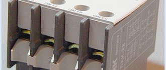
Block contacts
Block contacts are electromechanical devices used to switch control and signaling circuits.
Typically, such devices have from 1 to 4 normally open or closed contacts. They are installed on the side or front of the starter (contactor).
NC – contacts are used mainly in blocking circuits (see example below). But in addition to blocking circuits, they can also be used to connect an autonomous power supply or alarm system.
NO – contacts are used for signaling, for example, when the contactor is turned on, it is triggered and supplies voltage to the signal lamp, or a control signal to the controller/control station.
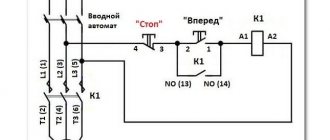
Electrical contactor interlock
Let's look at an example of how a contactor is electrically blocked using additional contacts.
When voltage is applied to the coil terminals of the contactor K 1, it operates together with its block contact K 1.1. The normally closed contact K 1.1 opens, interrupting the power supply to the coil of contactor K 2. A similar process occurs when contactor K 2 is turned on.
This electrical contact interlocking circuit prevents the simultaneous activation of two contactors at the same time. This connection of contactors is often used when connecting an asynchronous motor. Normally open contacts are not used in this circuit, but can be used in control and signaling circuits.
Normally closed or normally open valve for underfloor heating
The servo drive is commutator.
Selection and connection rules. This servo drive is sometimes called: Electric drive, servo motor, thermal drive, etc.
Its official name is electrothermal servo drive
(Simpler:
Thermal drive
). Servomotors are drives with an electromagnetic motor.
There are servos for three-way valves, information about this is here:
Such a servo drive ( thermal drive
) can be used for both underfloor heating and radiator heating. For both manifold and thermostatic valve (valve). In this case, we will look at the connection for underfloor heating and the connection for radiator control.
Normally open
— Open valve by default. That is, when there is no signal (voltage) to the servo drive, it is in the “Open valve” position. In this case, in the absence of voltage, the coolant passes through the open valve.
Normally closed
— Valve closed by default. That is, when there is no signal (voltage) to the servomotor, it is in the “Closed valve” position. In this case, in the absence of voltage, the coolant does not pass through the closed valve.
Universal, switchable thermal actuators
— such thermal actuators can be switched to one of two positions: Normally open and normally closed.
The type of servos can take different forms:
When the question arises about choosing an option
- open or closed type, then you need to understand the following:
If the valve remains in the open position for a longer period of time, the normally open mode is selected.
If the valve remains in the closed position for a longer period of time, the normally closed mode is selected.
In severe winter conditions, the normally open option is selected. In particular in Russia. In warm regions, you can choose a normally closed one. However, it all depends on many factors. The most common type of servos is normally open. In addition, when the servo drive fails, there is no risk of freezing the room from the cold.
Voltage servos are 220 volts, but there are also other voltages, for example, 24 volts. It is also possible that servos can accept direct current or alternating current. In most cases this is 50 Hz alternating current.
In order for the servo to start closing or opening the valve, it needs a signal in the form of voltage. The usual signal to the servo drive is the usual power supply, which is indicated in the servo drive data sheet. (220v/24v).
Let's consider such a thermal drive. Manufacturer: Oventrop.
There is such a mechanism inside:
Operating principle of servo drive
The operating principle of the drive is based on the expansion of liquid (toluene) in a bellows due to the passage of electric current through a nichrome heating element.
The servo drive mechanism has a spring mechanism and a container that contains a special liquid, which expands under the influence of temperature and puts pressure on the rod. The rod, extending, presses on the thermovalve rod and the valve closes. Under the influence of voltage, the liquid heats up and the liquid expands. That is, this servo drive does not have an electromagnetic motor. The use of force is taken from the expanding fluid under the influence of temperature, so this servo drive is called a thermal drive. Since the force of movement comes from the expansion of the liquid when it is heated.
Therefore, when voltage is applied to the servo drive, the drive does not close the valve instantly, but after some time has passed, which takes the liquid to warm up. This is about 1-3 minutes depending on the manufacturer.
When there is no voltage in the thermal drive, the valve returns to its original position when it has cooled down sufficiently. The servo takes much longer to cool down than it does to heat up. Therefore, the opening time of the thermal drive is from 5 to 15 minutes.
On the left is a heated servo drive, on the right is a cooled one.
The servo drive has a retractable mechanism on top; it is needed in order to:
Firstly
, determine the fit of the servo drive in the thermal valve.
Secondly
, notifies the valve mode: On/Off.
That is, if it is raised up, this indicates that the valve is closed. If it is down, the valve is open.
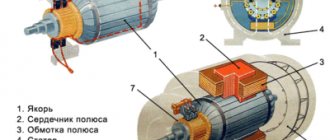
Relay design, designation and parameters
An electromagnetic relay is actively used to control various actuators, switch circuits, and control devices in electronics.
The relay design is quite simple. Its basis is a coil consisting of a large number of turns of insulated wire.
A soft iron rod is installed inside the coil. The result is an electromagnet. There is also an anchor in the relay design. It is attached to a spring contact. The spring contact itself is fixed to the yoke. Together with the rod and the armature, the yoke forms a magnetic circuit.
If the coil is connected to a current source, the resulting magnetic field magnetizes the core. He, in turn, attracts the anchor. The anchor is mounted on a spring contact. Next, the spring contact closes with another fixed contact. Depending on the relay design, the armature may mechanically control the contacts differently.
Relay device.
In most cases, the relay is mounted in a protective housing. It can be either metal or plastic. Let's look at the relay device more clearly, using the example of an imported Bestar electromagnetic relay. Let's take a look at what's inside this relay.
Here is the relay without the protective housing. As you can see, the relay has a coil, a rod, a spring contact on which the armature is attached, as well as actuating contacts.
On circuit diagrams, an electromagnetic relay is designated as follows.
The relay symbol in the diagram consists of two parts. One part (K1) is the symbol of the electromagnetic coil. It is designated as a rectangle with two terminals. The second part (K1.1; K1.2) are groups of contacts controlled by the relay. Depending on its complexity, a relay can have a fairly large number of switched contacts. They are divided into groups. As you can see, the designation shows two groups of contacts (K1.1 and K1.2).
How does a relay work?
The principle of operation of the relay is clearly illustrated by the following diagram. There is a control circuit. This is the electromagnetic relay K1 itself, the switch SA1 and the power battery G1. There is also an actuator circuit that is controlled by a relay. The executive circuit consists of load HL1 (signal lamp), relay contacts K1.1 and battery G2. The load can be, for example, an electric lamp or an electric motor. In this case, the HL1 signal lamp is used as a load.
As soon as we close the control circuit with switch SA1, current from power battery G1 will flow to relay K1. The relay will operate and its contacts K1.1 will close the actuator circuit. The load will receive power from battery G2 and lamp HL1 will light up. If you open the circuit with switch SA1, then the supply voltage will be removed from relay K1 and the contacts of relay K1.1 will open again and the lamp HL1 will turn off.
Switched relay contacts can have their own design. For example, a distinction is made between normally open contacts, normally closed contacts and switching contacts. Let's look at this in more detail.
Normally open contacts
Normally open contacts are relay contacts that remain open until current flows through the relay coil. To put it simply, when the relay is turned off, the contacts are also open. In diagrams, relays with normally open contacts are designated like this.
Normally closed contacts
Normally closed contacts are relay contacts that remain closed until current flows through the relay coil. Thus, it turns out that when the relay is turned off, the contacts are closed. Such contacts are shown in the diagrams as follows.
Switching contacts
Switching contacts are a combination of normally closed and normally open contacts. Switching contacts have a common wire that switches from one contact to another.
Modern widespread relays, as a rule, have switching contacts, but there may also be relays that have only normally open contacts.
For imported relays, normally open relay contacts are abbreviated NO. And normally closed contacts are NC. The common relay contact is abbreviated COM. (from the word common - “general”).
Now let's turn to the parameters of electromagnetic relays.
Parameters of electromagnetic relays.
As a rule, the dimensions of the relays themselves allow their main parameters to be printed on the housing. As an example, consider the imported Bestar BS-115C relay. The following inscriptions are written on its body.
COIL 12VDC is the rated operating voltage of the relay (12V). Since this is a direct current relay, the abbreviation for constant voltage is indicated (the abbreviation DC stands for direct current/voltage). The English word COIL is translated as “coil”, “solenoid”. It indicates that the abbreviation 12VDC refers to the relay coil.
Further on the relay the electrical parameters of its contacts are indicated. It is clear that the power of the relay contacts may be different. This depends both on the overall dimensions of the contacts and on the materials used. When connecting a load to the relay contacts, you need to know the power for which they are designed. If the load consumes more power than the relay contacts are designed for, then they will heat up, spark, and “stick.” Naturally, this will lead to rapid failure of the relay contacts.
For relays, as a rule, the parameters of alternating and direct current that the contacts can withstand are indicated.
For example, the contacts of the Bestar BS-115C relay are capable of switching an alternating current of 12A and a voltage of 120V. These parameters are encrypted in the inscription 12A 120VAC (the abbreviation AC stands for alternating current).
The relay is also capable of switching direct current with a power of 10A and a voltage of 28V. This is evidenced by the inscription 10A 28VDC. These were the power characteristics of the relay, or rather its contacts.
Relay power consumption.
Now let's turn to the power that the relay consumes. As you know, direct current power is equal to the product of voltage (U) and current (I): P=U*I. Let's take the values of the rated operating voltage (12V) and current consumption (30 mA) of the Bestar BS-115C relay and get its power consumption.
Thus, the power of the Bestar BS-115C relay is 360 milliwatts (mW).
There is another parameter - the sensitivity of the relay. At its core, this is the power consumption of the relay in the on state. It is clear that a relay that requires less power to operate is more sensitive compared to those that consume more power. A parameter such as relay sensitivity is especially important for self-powered devices, since the switched on relay consumes battery power. For example, there are two relays with power consumption of 200 mW and 360 mW. Thus, a 200 mW relay is more sensitive than a 360 mW relay.
How to check the relay?
The electromagnetic relay can be checked with a conventional multimeter in ohmmeter mode. Since the relay coil winding has active resistance, it can be easily measured. The resistance of the relay winding can vary from several tens of ohms (Ω) to several kilo-ohms (kΩ). Typically, the lowest winding resistance is found in miniature relays that are rated at 3 volts. Relays rated at 48 volts have much higher winding resistance. This can be clearly seen from the table, which shows the parameters of the Bestar BS-115C series relay.
| Rated voltage (V, constant) | Winding resistance (Ω ±10%) | Rated current (mA) | Power consumption (mW) |
| 3 | 25 | 120 | 360 |
| 5 | 70 | 72 | |
| 6 | 100 | 60 | |
| 9 | 225 | 40 | |
| 12 | 400 | 30 | |
| 24 | 1600 | 15 | |
| 48 | 6400 | 7,5 |
Note that the power consumption of all types of relays in this series is the same and amounts to 360 mW.
An electromagnetic relay is an electromechanical device. This is probably the biggest plus and at the same time a significant minus.
With intensive use, any mechanical parts wear out and become unusable. In addition, the contacts of powerful relays must withstand enormous currents. Therefore, they are coated with precious metal alloys such as platinum (Pt), silver (Ag) and gold (Au). Because of this, high-quality relays are quite expensive. If your relay still fails, then you can replace it.
The positive qualities of electromagnetic relays include resistance to false alarms and electrostatic discharges.
Home » Radio electronics for beginners » Current page
You might also be interested to know:
- Triac.
- Parameters of MOS transistors.
Examples
Example 1. Let’s draw a diagram that implements the following algorithm: if the pump is on, the green light is on, and if it’s off, the red light is on.
At the moment when the pump turns on, the limit switch (normally open contact), which we introduced into our circuit, closes inside it. At the same time, voltage “comes” to the coil of relay K1 - the relay is activated, opening the NC contact K1.1, and the red light goes out. At the same time, when the contact inside the pump closes, the green light comes on.
Example 2. Let's implement example 1 using a relay changeover contact.
In this circuit, relay contact K1.1 is a changeover contact. When the relay is in the “normal” state, the red lamp is on. When triggered, relay K1.1 changes its state and the green lamp lights up.
- Price: $1.66
- Go to the store
In today's review, I will share with you my impressions of a 5-pin automotive relay purchased on eBay, and also show one of the possible options for its use.
The relay was ordered almost simultaneously with the DRL kit that I talked about a few days ago. For what? Because when using a standard connection, when turning on the side lights or low/high beams, the DRLs still continued to light up. I didn’t find anything good in this, and therefore I began to think about automating their shutdown when turning on the headlights or low beam. The simplest and most logical option seemed to me to be using a relay.
By the way, this is one of the few purchases that I went to the local auto parts store before making. Imagine my surprise when I saw the price in the VAZ store: relay - 5 rubles (about $2.5), a block for it - 2.5 rubles ($1). Total, $3.5 per set offline with us without waiting, versus $1.66 with them. The choice is obvious