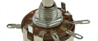
Potentiometer is a manually adjustable variable resistor with 3 terminals. Its two terminals are connected to both ends of the resistive element, and the third terminal (slider) is connected to a sliding contact that moves along the resistive element. The position of the slider determines the output voltage of the potentiometer.
Transistor tester / ESR meter / generator
Multifunctional device for testing transistors, diodes, thyristors...
More details
A potentiometer essentially functions as a variable voltage divider. A resistive element can be thought of as two resistors connected in series, where the position of the slider determines the ratio of the resistance of the first resistor to the second resistor.
A potentiometer is also commonly known as a variable resistor. The most common form is the single-turn variable resistor.
This type of variable resistor is often used in audio systems for volume control (logarithmic type), as well as in many other devices.
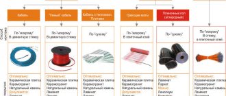
In the production of a potentiometer, various resistive materials are used: carbon, metal ceramics, wire, electrically conductive plastic, metal film.
In circuit diagrams, the potentiometer is designated as follows:
Potentiometer and rheostat: what is the difference
Let's consider RT in detail, since the properties of potentiometers will also be revealed in the process. So, the same variable resistor can be mounted on the circuit in two ways, creating two modes:
- parallel connection - PT. The potentiometer connection usually uses all 3 pins.
- sequential - rheostat. Only 2 contacts are used.
“Potentiometer” and “rheostat” are simply different options for including the same variable resistor in a circuit, respectively, in series or parallel. Both parts work specifically with R, U, I. But the proportionality of the changes is different, in the first case the voltage is regulated to a greater extent, in the second - the current.
Read also: Sin of sin, or Tantra in Russian
The rheostat has two outputs, the potentiometer has three (if used as the first, then only two contacts are connected). That is, the PC is included in the circuit like an ordinary resistor. Both are non-polarized and can work in reverse.
PT and PC are connected differently. The second, unlike the first, is usually an industrial device or on powerful equipment. Some schools taught lessons with a rheostat, so some may remember its shape: a large ceramic tube with a nichrome winding and a slider on the middle terminal that is not connected anywhere. RS has high power (passes powerful current) and low resistance (up to tens of ohms). It has significant inductance, which is taken into account in HF devices.
Voltage dividers are usually low-power, so they are rarely suitable for the role of PCs; in production, variables up to 10 W are positioned as the first, and from 10 W - as the second.
Variable as a rheostat
RS changes the overall resistance. circuits - it is this property that is important here; it is used in its full, most effective form to control (limit) the current.
It is connected to the circuit only in series: the switched-on variable is called a rheostat (this is the operating mode).
You can imagine the circuit as such, consisting of two ordinary resistors connected in series, that is, the slider divides the PC coil into the indicated elements. By adjusting R, the parameters of these resistors and, accordingly, the current in the circuit are reduced/increased.
How to connect the device correctly
Required tools and materials
To properly connect the device with your own hands, you need the following tools and materials:
- working potentiometer;
- set of wires;
- regular scissors;
- powerful soldering iron;
- special solder;
- measuring voltmeter;
- ball pen.
Potentiometer connection
You must connect the product yourself in the following sequence:
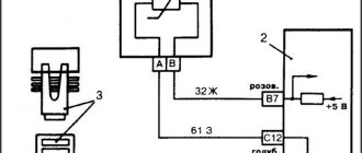
- The working sensor should be positioned in such a way that the special lever for regulating the electrical voltage is directed straight up, and the terminals for securing the wires are located near the person. The pins must be numbered from left to right using a ballpoint pen.
- The first pin must be connected to ground. To do this, you should cut a wire of a certain length and solder it well.
- The second terminal is necessary to secure the wire that sends electrical voltage to the sensor output.
- The third pin must be soldered to the input of the circuit.
- Next, after completing the previous steps, it is worth testing the correct operation of the sensor. To do this, you should use a measuring device. When performing this work, it is necessary to rotate the sensor slider from the lowest to the highest electrical voltage value. You can learn more about how to check the potentiometer from numerous photos on the Internet.
- After checking the quality of the sensor, you need to place it in the electrical circuit, and after that you need to cover the product with a protective casing.
Marking of variable resistors
Russian marking of variable resistances before 1980 - for example, SP4-18:
- The product type is designated SP.
- The first number is the type of material and manufacturing technology - 4.
- The second is the registration number of the resistor type -18.
Group marking by manufacturing technology and material:
- 1 – non-wire thin-layer carbon and boron carbon;
- 2 – non-wire thin-layer metal film and metal oxide;
- 3 – non-wire composite films;
- 4 – non-wire composite volumetric;
- 5 – wire;
- 6 – non-wire thin-layer metallized.
Now there is a new system for marking variables and trimming resistors - for example, RP1-46:
- The product type is designated RP.
- The first digit determines the group according to the material of the resistive element (1 – non-wire, 2 – wire and metal foil).
- The second digit is the registration number of the development of a specific type of resistance.
Attention! There is no single standard for marking regulating resistors - the marking of imported ones differs from Russian ones.
Rheostat
See also: Liquid rheostat
The most common way to change the resistance in a circuit is to use a rheostat
.
The word rheostat
was coined around 1845 by Sir Charles Wheatstone, from the Greek ος
rheos
meaning "flow", and -στάτης -
states
(from ἱστάναι
gistanai
, "to set, make to stand") meaning "setter, regulating device",[6] [7][8] which is a two-terminal variable resistor. The term "rheostat" is becoming obsolete,[9] being replaced by the general term "potentiometer". For low power applications (less than 1 W), a three-terminal potentiometer is often used, with one terminal unconnected or connected to the wiper.
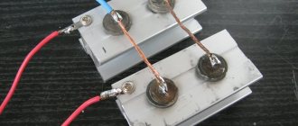
If the rheostat is to be rated for higher power (more than about 1 W), it can be constructed with a resistance wire wound around a semicircular insulator, with the wiper sliding from one turn of wire to the next. Sometimes the rheostat is made from resistance wire wound around a heat-resistant cylinder, and the slider consists of several metal fingers that easily grip a small portion of the resistance wire turns. The "fingers" can be moved along the coil of resistance wire using a sliding handle, thus changing the point of "touch". Wire wound rheostats, rated up to several thousand watts, are used in applications such as DC motor drives, electric welding controls, or generator controls. Rheostat ratings are given at full resistance value, and the permissible power dissipation is proportional to the proportion of the total resistance of the device in the circuit. Carbon rheostats are used as load banks for testing car batteries and power supplies.
- Charles Wheatstone 1843 rheostat with metal and wood cylinder
- Charles Wheatstone's 1843 rheostat with moving whisker
- Rheostat electronic symbol
- Electronic symbol for preset rheostat
- Powerful wire wound potentiometer
Types and features
By the nature of the change in resistance:
- Linear . Marked with the letter "A". The resistance varies directly depending on the angle of rotation of the movable contact.
- Logarithmic . Marked with the letter "B". When the slider starts moving, the resistance changes quickly and then slows down.
- Exponential . Marked with the letter "C". When you turn the knob, the resistance changes exponentially, that is, at first slowly, then faster. Letter designations may not always correspond to reality, as this depends on the manufacturer of the device. Therefore, to determine the type of potentiometer, it is necessary to study the technical description of this instance.
By type of potentiometer housing:
- Assembly . Installed by soldering to the circuit board.
- Stationary negotiable . They are located on the body of various devices. In turn, revolving potentiometers are divided into several types: - Single-turn.
The sliding element can rotate one revolution, or more precisely, about 270 degrees. A full rotation is not possible, since the rest of the rotation sector contains contact terminals. Single-turn variable resistors have become the most popular in devices that do not require more than one turn for adjustment. - Multi-turn.
The moving contact has the ability to perform several revolutions to increase the accuracy of parameter control. Such variable resistors are usually equipped with a helical or spiral resistive element and are used in devices that require increased resolution and adjustment accuracy. Multi-turn models are most often used in the form of trimmers on the circuit board. - Double.
They include two variable resistors located on the same axis. This makes it possible to adjust two resistances in parallel. In such models, the most popular is the use of resistances with logarithmic and linear dependence. They are used in stereo controls for sound amplifiers, radios and other devices that require simultaneous adjustment of two separate channels.
- Linear (slider) . Such models of potentiometers are divided into types: - Sliding potentiometer.
A single linear potentiometer is used for audio equipment devices. Such models are made of conductive plastic to improve the quality of the product and are used to adjust one channel. — Linear double.
This model is capable of regulating two separate channels at once. Often used to configure stereo equipment in professional audio devices that require control of two channels. — Slider multi-turn.
Its design includes a spindle that converts rotational motion into linear translational movement of the slider against resistance. It is used in places where increased resolution and accuracy are required. This model is installed to adjust parameters on the circuit board.
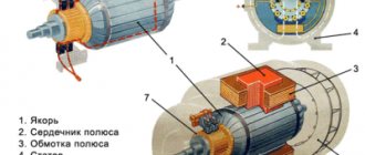
Design and operation
The voltage that is supposed to be regulated is applied to the terminals of the resistive element. The moving contact is a control element that is activated by rotating the handle. A voltage is removed from the moving contact, which can range from zero to a maximum value equal to the input voltage to the potentiometer, and depends on the current position of the moving contact.
The potentiometer acts like a variable resistor, but functions as a voltage divider. Its resistive component consists of two resistors that are connected in series. The position of the sliding contact is decisive in determining the ratio of the resistance value of the 1st resistor to the 2nd.
The most popular has become the variable single-turn resistor. It is widely used in radio engineering as a volume control and in other devices. In the manufacture of potentiometers, different materials are used to make the resistor: metal film, conductive plastic, wire, cermet, carbon.
Modifications
To find out more precisely what a potentiometer is, a review of some device models will help. First, let's look at the Skal modification. In this series, models under the index 103, 105, 107 are especially popular.
Brief description of devices:
- Skal 103 is a device designed to adjust resistance in an alternating current circuit. This device features exclusively movable contacts. There is one key, a passive resistor, placed near the terminals. A software sampling function is provided; there is no rheostatic mode. The housing marking is P20, the potentiometer is adjusted by levels.
- Model 105 is an automatic device used in AC systems. A passive type resistor is installed, the key is located near the terminals. The modification is optimally suited for computers because it has a high cutoff frequency and a linear distortion parameter of 56 dB.
- Option 107. This device has a level frequency of 2400 kHz, a resistive switch, and passive resistors located in the lower compartment of the case. Its marking is PP21, the maximum lowering band is 2.3 microns, there is a rheostat mode.
Integrate Potentiometer with Arduino
There's a lot you can do with an Arduino board and a potentiometer But before that you should know that to make a simple example where you will start to see how the potentiometer works, you can use any of the analog pins on your board. For example, in Arduino UNO you can use A0 to A5.
Since they have 10-bit resolution, this means you have 1024 possible values (0000000000-1111111111), and since the available voltage range is 0V to 5V, it can be calibrated so that 0000000000 (or 0) is 0 V, and 1111111111 (or 1023) was 5 V so it could detect voltage spikes of 0.004 V (5/1024).
to link , you can simply do the following:
- Connect the potentiometer input to the 5V board.
- The output of the potentiometer will be connected to one of the analog inputs. For example, A1.
- As for the other remaining potentiometer pin, you should connect it to GND.
Once this is done, you can create a small sketch in the Arduino IDE to be able to test how the potentiometer works. With this code you will be able to read the voltage values obtained from the output when you turn the potentiometer cursor.
//Ejemplo de prueba de potenciómetro long valor; void setup() { //Inicialisamos la comunicación serial Serial.begin(9600); //Escribir el valor leído por el monitor serie Serial.println("Inicio de sketch - Valores del potenciómetro"); } void loop() { // Leer los valores del A1 valor = analogRead(A1); //Imprimir en el monitor serie Serial.print("Valor leído = "); Serial.println(valor); delay(1000); }
For more information you can...
Basic division of potentiometers:
a) the nature of the change in resistance:
- linear (indicated by the letter A) – the change in resistance is directly proportional to the angle of rotation of the sliding contact;
- logarithmic (denoted by the letter B) - the change in resistance occurs quickly from the beginning, then slows down;
- exponential (denoted by the letter C) - the change in resistance occurs slowly at the beginning, then accelerates. Please note that sometimes the potentiometer type designation (letters A, B, C) may be different depending on the manufacturer of the potentiometer, so you should check this with the technical description of the specific unit.
b) body type:
— mounting (for soldering to the board);
— reversible stationary (placed on the body);
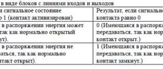
| Type | Description | Application |
| Single-turn | The engine rotates one revolution (approximately 270 degrees or 3/4 of a full revolution) | Most often, such potentiometers are used in devices where one revolution is enough to make adjustments. |
| Multi-turn | The resistor motor can be rotated multiple times (mostly 5, 10 or 20) to improve accuracy. In them, as a rule, the resistive element has a spiral or screw shape. | They are used where high accuracy and resolution are required. Multi-turn potentiometers are often used as trimmers on a printed circuit board. |
| Twin | Combines two separate resistors on one shaft, allowing parallel adjustment of two channels. The most common potentiometers are linear and logarithmic resistance. | It is used, for example, in stereo audio volume controls or other devices where it is necessary to simultaneously adjust two independent channels. |
— slider (linear);
| Type | Description | Application |
| Slider potentiometer | Single slide linear potentiometer is mainly designed for audio devices. High quality resistors are often made from conductive plastic. | For one channel |
| Dual slide potentiometer | The double potentiometer, as well as the double reversible potentiometer, allows you to adjust two independent channels. | Often used to control stereo in professional audio systems and other devices where it is necessary to control two channels simultaneously. |
| Multi-turn slide potentiometer | It has a spindle that converts rotational motion into translational linear movement of the potentiometer slide along the resistive element. | Used where high accuracy and resolution are required. A multi-turn slide potentiometer is used as a trimmer on a printed circuit board, but not as often as a rotary multi-turn potentiometer. |
Potentiometer design
A potentiometer most often has 3 terminals: two terminals are connected to each other by a constant resistance, the third terminal has a movable contact that moves along a surface of constant resistance.
Operating principle [edit | edit code ]
A potentiometer is a voltage divider made of resistors (resistive divider) with variable resistance (variable resistors).
A source whose voltage is known ( U 0 <0>>) and a source whose voltage needs to be determined ( U x > ) are connected to the voltage divider.
One of the voltages being compared, known with sufficient accuracy, is usually called the “reference voltage” or “reference EMF”. In foreign literature, the reference voltage is called “reference voltage” and is usually denoted U ref >.
By manually or automatically adjusting the resistance of the voltage divider, we ensure that the voltage UK > removed from the divider becomes equal to the voltage (or emf) U x > . Voltage equality (U x = UK =U_>) is usually called “stress balance”. The “balance” indicator is a sensitive low current (or voltage) meter, often called a “null indicator” and indicated in the figure by the letter “O”. When U x = UK, =U_,> the current I x > flowing through the zero indicator “O” will be equal to 0.
Historically, sensitive galvanometers were the first to be used as null indicators. In modern electronics, high-gain differential amplifiers are used as a null indicator.
For the diagram shown at the top of the figure, according to Kirchhoff’s rules
I x + IK = I 0 ; +I_=I_<0>;> U x = UK = IK ⋅ R 1 ; =U_=I_cdot R_<1>;> U 0 + I 0 ⋅ ( R 0 − R 1 ) + IK ⋅ R 1 = 0 , <0>+I_<0>cdot (R_<0>-R_<1> )+I_cdot R_<1>=0,>
and taking into account I x = 0 =0>:
IK = I 0 ; =I_<0>;> U x = I 0 ⋅ R 1 ; =I_<0>cdot R_<1>;> I 0 = U x R 1 ; <0>=>>>;> U 0 + I 0 ⋅ ( R 0 − R 1 ) + I 0 ⋅ R 1 = U 0 + I 0 ⋅ R 0 = 0 ; <0>+I_<0>cdot (R_<0>-R_<1>)+I_<0>cdot R_<1>=U_<0>+I_<0>cdot R_<0>=0;> U 0 = − I 0 ⋅ R 0 = − U x R 1 ⋅ R 0 ; <0>=-I_<0>cdot R_<0>=->>>cdot R_<0>;> U x = UK = − U 0 R 1 R 0 , =U_=-U_<0>>>, > 0>1>
For the diagram shown below the figure
U x = UK = − U 0 R 1 R 1 + R 2 . =U_=-U_<0>1>+R_<2>>>.> 1>
That is, knowing the ratio of the resistances of the voltage divider resistors when the voltages are equal (“balance”), one can numerically express one voltage ( U 0 <0>> or U x >) through another voltage ( U x > or U 0 <0>>, respectively ).
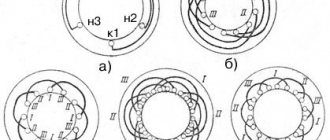
The flux chord was historically used as a variable resistance. The reochord was a piece of tensioned wire of a constant cross-section with three electrical leads. The first two leads were attached to the ends of the wire, and the third (slider) could be moved along the wire. The electrical resistance R of a homogeneous piece of wire of length l and constant cross-section S is expressed by the formula R = ρ l S, ho >,> where ρ ho > is the specific electrical resistance of the wire material. Knowing the length of the wire L, the distance l from the edge of the wire to the slider and the voltage U 0 <0>> between the ends of the wire, we can determine the voltage UK > (equal to U x > ) between the slider and the end of the wire:
U x = UK = − U 0 R 1 R 0 = − U 0 ρ l S ρ LS = − U 0 l L . =U_=-U_<0>>>=-U_<0>< ho >>< ho >>>=-U_<0>>.> 0>1>
Reochords, which are a piece of wire, are practically not used in modern potentiometers; they are only sometimes used for demonstration purposes. A modern rheochord is a variable resistor, usually made in the form of a single-layer spiral winding of high-resistance wire on a straight or toroidal base (frame). The name "reochord" in potentiometers is firmly attached to these variable resistors.
Historically, electrochemical sources of time-stable and reproducible voltage—normal electrochemical cells—have been used as a reference voltage source (RV). In modern potentiometers, semiconductor precision IONs are usually used as reference voltage sources - temperature-compensated zener diodes and bandgap IONs.
If loading a source of known voltage onto a resistive voltage divider is unacceptable, for example, in the case of using sources with high internal resistance, then another source with a sufficiently low internal resistance is preliminarily calibrated against this source.
When the voltages of the resistive divider and the reference voltage are balanced, the current through the null indicator (galvanometer) is zero. Thus, the reference voltage source operates at idle balance, which allows precision sources with high internal resistance, such as normal electrochemical cells, to be used as reference voltage sources. Similarly, for the same reason, it is possible to measure the EMF of unknown voltage sources with high internal resistance without distorting the measurement result, for example, the EMF of electrochemical potentiometric sensors.
How to choose a potentiometer
The main role when choosing a potentiometer is played by its impedance rating - this is the level of resistance between the fixed contacts. The potentiometer should be selected based on the value of the external variable resistor specified in the operating manual for a particular device. For example, for frequency converters OWEN PCHV1, PCHV2, PCHV3, potentiometers with ratings of 1 kOhm, 5 kOhm, 10 kOhm are used, for power regulators Meyertec DRU3-125/150/200 - 10 kOhm.
In some cases, it is necessary to take into account other parameters, namely:
- angle of rotation of the adjusting unit;
- error;
- wear resistance;
- thermal resistance when heating;
- working temperature.
Why is it important? When operating equipment in a closed space, the potentiometer must not overheat.
When working with frequency converters and power regulators, the current in Meyertec potentiometers is small, heat losses are negligible, so there is no need to remove heat.
Important! Before putting the circuit into operation, it is necessary to check all soldering and insulation points, and also follow safety regulations.
Features of potentiometers for measuring ultra-low voltages [edit | edit code ]
When measuring ultra-low voltages (at the level of microvolts - fractions of a millivolt), the distortion of the measurement result from the thermo-EMF of “parasitic” thermocouples formed at the points of electrical connection of dissimilar conductor materials (for example, copper conductors and high-resistance conductors of variable resistors) becomes significant if the temperature of these connections (joints) is not equal. Without the use of special measures, the values of parasitic thermo-EMF can reach tens of microvolts. For example, the thermo-EMF of a copper-tin-lead solder pair is about 3-7 µV/K, which, when the measured voltage is in the range of a few to tens of microvolts, can give a relative measurement error of several tens of percent, which is usually unacceptable. Therefore, when designing such potentiometers, special measures are used to reduce parasitic thermo-EMF. A radical measure is careful thermal insulation of the device from the external environment, sometimes thermostatting. For soldering electrical connections, solders are used that produce low thermal EMF when paired with copper, for example, tin-cadmium solders, whose thermal EMF when paired with copper is less than 0.3 μV/K.