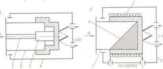
Design and principle of operation
Modular contactors are abbreviated as KM and MK, the devices consist of 2 systems: contact and arc extinguishing, the control element is an electromagnet, and there is also an additional set of contacts.
The operating principle of modular contactors is as follows:
The magnetic field of the network affects the contacts, and they close. When the device is turned on, its coil is saturated with voltage, a magnetic metal armature engages with the core, and then the contacts open or close, it all depends on the initial position of the equipment.
The contact spring ensures fixation of the tension of the contacts, during the joining of which the movable one rolls onto the stationary one. The starter is equipped with additional contacts, with their help the coil is controlled and the reverse motion is activated.
The arc extinguishing system is a limiter that is triggered when the electric arc is abruptly interrupted or voltage surges are observed.
The instructions on how to connect a modular contactor contain extremely useful recommendations that are important to read in advance.
What is a contactor
This is what the currently valid GOST 17703-72 “Electrical switching devices” says about this. Basic concepts.”
Here a spring is used as self-return. The possibility of frequent current switching is provided by the design itself.
Some questions arise regarding the last wording - “powered by a motor drive”. Which element is considered a motor drive?
To figure it out, let’s turn again to GOST and find the appropriate definition.
Can we assume that the contactor has an electric magnetic drive? What does another GOST 24856-2014 “Pipeline fittings” say about this? Terms and Definitions."
As you can see, this is exactly what you need. In our case, the moving contacts are precisely driven by the electric magnetic field of the coil.
The principle of operation in contactors is pulling - when voltage is applied, part of the core is retracted and the fixed contacts are closed with the moving ones.
However, in addition to the above definitions of contactor, there are several more. For example, in STO 173330282.27.010.001-2008 “Electric power industry. Terms and Definitions." Here is a more simplified formulation:
And here’s what GOST 60309-4-2013 “Plugs, sockets and connectors for industrial use” says.
The meaning in all these decodings of names is the same, and there are no global discrepancies.
How to connect a contactor
When connecting a contactor, you immediately need to decide on the mechanism that it will turn on. This could be a motor, pump, fan, heating elements, compressors, etc. The main feature of a contactor that distinguishes it from a machine is the absence of any protection. Therefore, when thinking through the circuits for switching on electrical equipment through a contactor, it is necessary to take into account the current-limiting and heating elements. To limit and shut down equipment in case of short circuits and loads many times higher than the rated load, fuses and circuit breakers are used. Thermal relays are used to prevent long-term slightly exceeding the rated currents of operating equipment.
In order to correctly connect a contactor to a circuit, you need to clearly understand which of the contacts are power and which of them are auxiliary, that is, block contacts. You also need to look at the ratings of the switching coil. The voltage, its type and magnitude, as well as the currents that flow through it for normal operation must be indicated there. During operation, power contacts may burn, so they must be inspected and cleaned regularly.
How to connect a modular contactor
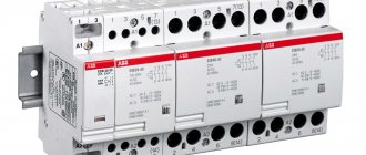
A modular contactor is a type of conventional switching devices of the same type, only they are mainly used for switching switchboards on and off remotely. That is, turning it on, power is supplied to a group of machines, each of which is responsible for its own specific circuit. It is installed on a DIN rail. Can switch both direct and alternating current circuits.
Connecting a contactor via a button
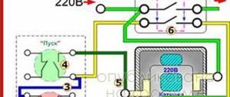
To connect the contactor via a button, you need to study the attached diagram below. It is designed to start a load, in this case a motor, from a contactor whose coil is designed for 220 Volts alternating voltage. Depending on the voltage, it is worth considering its power supply. Therefore, when purchasing and selecting a contactor, it is worth taking this nuance into account. Since if the electromagnet is designed for constant voltage, then such a source will be needed.
When you press the start button, the contactor electromagnet coil will receive power and it will turn on. The power contacts will close, thereby supplying voltage to the asynchronous motor. The block contact of contactor K1, which is connected in parallel to the stop button, will also close. It is called by electricians a self-retaining contact, since it is this that supplies power to the switching coil after the start button is released. When you press the stop button, the power from the electromagnet is turned off, the power elements of the contactor break the circuit and the engine turns off.
Connecting a contactor with a thermal relay
The thermal relay is designed to prevent prolonged minor current overloads during operation of electrical equipment, because overheating negatively affects the condition of the insulation. Frequent excesses of temperature and current will lead to its destruction, and therefore to a short circuit and failure of an expensive actuator.
When the current in the stator circuit of the electric motor increases, the elements of the thermal relay KK will heat up. When the set temperature, which can be adjusted, is reached, the thermal relay will operate and its contacts will break the circuit of the electromagnet coil of the KM contactor.
For safety reasons, you must remember that work in the contactor circuit must be carried out when it is completely de-energized. In this case, the power supply must be locked with a key or prohibiting sign from unauthorized or erroneous activation. And also you cannot turn on this device with the arc chutes removed, this will lead to a short circuit.
What are contactors used for?
Electricity has become a part of our lives. We can no longer imagine how we can do without it. Every day we use electrical appliances, turn them on and off and don’t think about what happens inside the devices.
We all know that you need to use a switch to turn on the light. What if the device operates in automatic mode and must turn on and off independently, such as a refrigerator or air conditioner? For remote switching, or in simple terms, turning on and off electricity consumers, there are contactors .
We don’t see contactors in everyday life, since contactors are components of various devices and only people who are professional electrical engineers can get to them. Contactors are mainly used in the professional field - from heavy engineering to housing and communal services.
All contactors are structurally similar. They consist of movable and fixed contacts (the movable contacts are connected to the movable traverse of the magnetic system). The contactor is controlled by an electromagnetic coil. Voltage is applied to the coil, an electromagnetic field arises, which, overcoming the resistance of the spring, attracts the moving part of the magnetic system along with the moving contacts attached to it. The contacts close and the consumer is connected to the electrical circuit.
There are many series (names) of contactors. Each series has its own specialization. Among them there are more universal series, and highly specialized ones, used only in special cases.
The main sequence of rated currents of EKF contactors consists of two series of KME PROxima and KTE PROxima and includes a sequence of rated currents from 9 to 630A.
KME PROxima contactors have a range of currents from 9 to 95A, controlled by an alternating current coil, voltage 230 or 400A - these coils are included. You can change the coils and get a contactor with 24, 36, 110V AC coils. These are quite universal contactors - their range of applications is quite large. They can be used to control three-phase asynchronous motors, lighting, heating units and many other equipment powered by three-phase current.
If we consider the widespread use, we can say that up to 90% of all generated electrical energy is spent in electric motors and 60% of this amount in electric motors with a power of up to 45 kW, which are controlled by PROxima KME contactors. KME PROxima is the most popular contactor. The technical characteristics of PROxima KME make it possible to use them for lighting, where it is necessary to pass current through a contactor for a long time and use them to operate a discrete supply line in various technological processes, where on-off cycles can reach 2400 per hour. Very often there is a need to control a single electric drive. These are installations such as local ventilation, various types of gates, and simple pumps. In such cases, in addition to the start and stop function, it is necessary to protect the motor. A starter is used for this. The starter is a contactor with a thermal relay. The contactor switches the electrical circuit, and the thermal relay protects the electric motor from overload, phase loss, and ultimately from motor failure. The operating principle of a thermal relay is based on the different coefficient of expansion of metals when heated. Two such metals are combined into one plate. When heated, such a plate bends in a strictly defined direction and its bending depends on the amount of heating. In a thermal relay, current passes through such a plate, and if the current is higher than permissible, then the bimetallic plate bends and, by pressing the lever, turns off the contact through which the contactor’s power passes and the contactor turns off.
The EKF range includes starters in a KME housing with an IP65 EKF PROxima electrical element with or without operation indication. These starters have “start” and “stop” buttons. Indication is necessary when the controlled equipment is located far away and it is visually impossible to determine whether it is working.
The second most popular contactor is the KHPP PROxima contactor . It is designed to work with currents from 115 to 630A and a control coil of 230, 400V. Since the switched currents are significantly different from the currents of the PROxima CHP, the PROxima CHP is more massive and larger in appearance than its “younger brother”. The difference in appearance is due to the need to use larger cross-sections of current-carrying parts and a larger contact area of the main contacts.
The use of KHP PROxima contactors is similar to the use of KME contactors, only the switched currents are much higher, but there is also a difference. KHP PROxima is used in various types of lifting mechanisms - electric cranes, beam cranes, hoist lifts. In these mechanisms, contactors operate under particularly difficult conditions. Starting is difficult due to the presence of a load on the lifting mechanism, and the crane is often stopped by connecting a counterflow, when the engine runs against the movement of the load, thereby slowing it down. At such moments, a special load falls on the contactor - overload currents reach 10 - 12 rated currents of the contactor, but the PROxima KHP is designed to work in such conditions, therefore it is the second most popular type of contactor, due to the prevalence of electric motors with a power of over 45 kW.
The EKF product range includes the PROxima FEA mini-contactor . They are designed for currents of 6-16A, with a control coil of 24, 230, 400V and complement PROxima KME contactors. Where there is a limitation in volume, PROxima FMC mini-contactors are used - these are devices such as air conditioners, refrigerators, and other devices with a minimized working space. Mini contactors can be installed in plastic boxes together with modular equipment and therefore can be used to control heated floors, ventilation units and many other three-phase loads.
Especially for use in conjunction with modular equipment, the EKF range includes a modular contactor KM PROxima . KM PROxima is designed to operate with currents of 16-63A and a 230V AC coil. This contactor differs from others not only in the modular design of the housing, but also in the variety of switching programs. It has two, three and four main contacts, which can be either normally open or normally closed and various mixed options.
Such a variety of switching programs has led to wide application possibilities for KM PROxima contactors. This includes the control of low-power engines, lighting control, and the inclusion of various utility equipment - from electric boilers to ventilation. That is, they are used both in industry and in households.
KMEp PROxima contactors are a highly specialized contactor with rated currents of 9-95A. The contactor coil is designed to operate with direct current voltages of 24, 110,220V. Its use is due to the presence of separate control systems for critical production processes that use direct current and can be protected from voltage failure. For example, in the Moscow metro the control system is built on a direct current voltage of 110V. Thus, in the Moscow metro all contactors operate on direct current.
Connection diagrams for a magnetic starter with a 220 V coil
Before we move on to the diagrams, let’s figure out what and how these devices can be connected. Most often, two buttons are required - “start” and “stop”. They can be made in separate housings, or they can be a single housing. This is the so-called push-button post.
Buttons can be in the same housing or in different ones
Everything is clear with individual buttons - they have two contacts. One receives power, the other leaves it. There are two groups of contacts in the post - two for each button: two for start, two for stop, each group on its own side. There is also usually a ground terminal. Nothing complicated either.
Connecting a starter with a 220 V coil to the network
Actually, there are many options for connecting contactors; we will describe a few. The diagram for connecting a magnetic starter to a single-phase network is simpler, so let's start with it - it will be easier to understand further.
Power, in this case 220 V, is supplied to the coil terminals, which are designated A1 and A2. Both of these contacts are located at the top of the case (see photo).
This is where you can supply power to the coil.
If you connect a cord with a plug to these contacts (as in the photo), the device will be in operation after the plug is inserted into the socket. In this case, any voltage can be applied to the power contacts L1, L2, L3, and it can be removed when the starter is triggered from contacts T1, T2 and T3, respectively. For example, a constant voltage from a battery can be supplied to the inputs L1 and L2, which will power some device that will need to be connected to the outputs T1 and T2.
Connecting a contactor with a 220 V coil
When connecting single-phase power to the coil, it does not matter which output is supplied with zero and which with phase. You can switch the wires
Even most often, the phase is supplied to A2, since for convenience this contact is located on the bottom side of the housing. And in some cases it is more convenient to use it and connect the “zero” to A1.
But, as you understand, this scheme for connecting a magnetic starter is not particularly convenient - you can also supply conductors directly from the power source by building in a regular switch. But there are much more interesting options. For example, you can supply power to the coil through a time relay or a light sensor, and connect the street lighting power line to the contacts. In this case, the phase is connected to contact L1, and zero can be taken by connecting to the corresponding coil output connector (in the photo above it is A2).
Diagram with start and stop buttons
Magnetic starters are most often installed to turn on an electric motor. It is more convenient to work in this mode if there are “start” and “stop” buttons. They are connected in series to the phase supply circuit to the output of the magnetic coil. In this case, the diagram looks like the figure below
note that
Switching diagram of a magnetic starter with buttons
But with this method of switching on, the starter will operate only as long as the “start” button is held down, and this is not what is required for long-term operation of the engine. Therefore, a so-called self-catching circuit is added to the circuit. It is implemented using auxiliary contacts on the starter NO 13 and NO 14, which are connected in parallel with the start button.
Connection diagram for a magnetic starter with a 220 V coil and a self-retaining circuit
In this case, after the START button returns to its original state, power continues to flow through these closed contacts, since the magnet has already been attracted. And power is supplied until the circuit is broken by pressing the “stop” key or by triggering a thermal relay, if there is one in the circuit.
Power for the motor or any other load (phase from 220 V) is supplied to any of the contacts marked with the letter L, and is removed from the contact marked T located underneath it.
It is shown in detail in what order it is better to connect the wires in the following video. The whole difference is that not two separate buttons are used, but a push-button post or push-button station. Instead of a voltmeter, you can connect a motor, pump, lighting, or any device that operates on a 220 V network.
What is a contactor and why is it needed?
In electrical networks, you constantly have to turn on or off various loads or control their operation. As we know, in everyday life there are mechanical switches and switches for these purposes. But such devices have a very limited durability, and for large electrical systems, control using mechanical switches is an inconvenient and ineffective way. That is why a device was created that has a huge service life, allows you to perform on and off cycles up to several thousand times per hour, and most importantly, makes it possible to control the load remotely. In simple words, this is a switch.
A contactor is an electromagnetic device designed for frequent switching on and off of electrical circuits remotely.
Electromagnetic contactors are used in all areas of our lives. They turn on street lighting, control the shutdown of high-voltage power lines, lines of transport systems (tram, trolleybus, railway), and are widely used in construction and industry to start powerful power plants, engines, machines and other equipment.
Moreover, such switching devices are also used in residential buildings for various purposes, such as, for example, turning on electric heating devices or water heaters, to control ventilation units, water supply or sewage pumps. Progress does not stand still, and at the moment, smart home systems controlled by contactors or groups of such devices are gradually entering the lives of ordinary people.
These devices play a huge role in electrical safety and, as a result, preventing fires from ignition of electrical equipment or power lines.
These devices have a number of advantages over various modular devices:
- Can connect to any network;
- They have compact dimensions;
- Absolutely silent in operation;
- Can be used at high powers and high currents;
- Easy to operate and easy to install;
- Can work in any conditions.
Types of contactors by purpose
- Remote switching devices (switching off, switching). When operating a complex of electrical installations, it becomes necessary to implement a certain power supply algorithm. Manual control: button, switch. The operator gives a signal at the right moment, the AC contactors are activated, switching the power according to a given operating pattern. For example, by pressing one button you can start an entire plant: conveyor, machines, lighting, ventilation system. By connecting many contactors in a certain way, it is possible to automate the power system on the control circuit (in this case, starting commands are given manually). In automatic mode, the command is given using an electronic circuit. The program controls production cycles at the right time, starting and stopping electrical installations. At the same time, any linear contactor can be equipped with a protection function: for example, a limit switch or thermal relay. When certain emergency conditions are created, the power to the coil is cut off and the operating contacts are opened.
- Switching on a powerful electrical installation using a low-current line, or again with a button (switch). A typical example is an electric motor starter.
It would seem, what does a modular contactor have to do with it: what is it for if you can use a button or a switch? Indeed, power can be supplied to the electrical installation directly using the contacts of the button. However, for a reliable connection of a powerful consumer, the contact group and the closing mechanism must be massive, and great force must be applied when turning on. The same force must be used to de-energize. This is not always convenient, especially in an emergency. Therefore, the device with which the operator directly works is compact, it is designed for low current (the consumption of the contactor coil is small), and a small force is required to activate it, especially on the off button. And the linear contactor itself can be quite large, and it operates instantly. Another reason why power separation of control and power lines is used is the high frequency of on and off cycles. For example, electric vehicles. The driver presses the accelerator pedal up to a thousand times per shift. If you equip the lever itself with power contacts, it will be inconvenient to use. Therefore, the pedal only supplies a weak current to the coil, and the line contactor starts the powerful electric motor.
Many of you, being near the driver's cabin, have heard regular loud clicks when pressing the pedal. This is exactly how a line contactor works.
Various drive types
- Electromagnetic is the main type and the most common. We discussed the principle of its operation in detail at the beginning of the article. Unless you can focus on the holding mechanism of the working coil. Most push-button (magnetic) starters do not have a locking button. That is, after the operator removes his finger, the power to the electromagnet should disappear. The design of most starters takes this point into account. There is a contact group on the end plate pusher that closes the solenoid circuit. While the entire electrical installation is working, there is power on the coil. If the voltage drops for a short time (emergency situation, or the disconnect button is pressed), all circuits are broken and the switch is turned on again. This adds safety during operation of the mechanism. After an uncontrolled power restoration, the electrical installation will not start until the operator decides to turn it on.
Information:
- When applying direct voltage (ordinary switch), dangerous situations sometimes arose:
the power is lost (line failure), the electrical installation is de-energized;
- the working day is over, the switch remains closed (the machine is not working, everyone has forgotten about the accident);
- power on the line is restored, machines, heating elements, etc. begin to work in the deserted workshop.
The use of contactors eliminates such situations.
Contactor design
To understand the principle of operation of a contactor, it is necessary to study its structure. After all, the device itself consists of several parts. Let's start with the coil. It is needed to create a magnetic current. If the coil is also a choke, then it provides the driving forces for the operation of the devices. To avoid problems, it is worth checking the voltage of the new coil.
When replacing, there are several important points to check. Such as no contact between moving parts and no air gap when the armature and core come into contact. The next part is the contact spring. Maintains fixed contact tension. After the contacts are joined, the moving one rolls over to the stationary one. In this case, destruction of oxide films and various chemical compounds that appear on the surface of the contacts occurs. If, when moving the contacts, the movable one ends up on the stationary one, then this is called pre-tensioning of the contact spring. This helps reduce vibration from one contact to another.
The next part of the modular contactor is the moving part. It consists of contacts that move and create work. And one more part of the device is the closing contacts. It is on them that the moving contacts move in order to create work. The last two parts can be combined into one phrase - contact system. After all, in essence, the parts differ only slightly, but together they create a certain force. It should be taken into account that they are attached to the anchor, but are located in different places, because the movable ones will be on the traverse, and the stationary ones will be on the hull.
When the contacts are not touching and there is no current flowing through them, this is called a “resting state.” When voltage is applied to the coil, an electromagnetic field is created, which creates EMF, electromotive force. Power contacts on the EMF attract the core. If the voltage supply is stopped, the electromagnetic field will disappear and the armatures (cores) will not be held. In this case, with the help of a spring, all contacts will return to their original position, opening the circuit. This is the basic principle of operation of the contactor. You can take a closer look at how the device works and what it consists of in the video below:
Design and operation scheme
Now we can say that modular contacts (like other contactors or starters) work by applying or disconnecting voltage to an electromagnetic coil. The instructions for connection and operation are quite simple and will not force you to tinker with them for a long time, because with use you will easily master the principle of operation of the device.
Operating principle of contactor
Externally, the contactor is a coil of wires, inside of which there is a core, or cylinder, mechanically connected to the electrical closing and opening contacts. Closing contacts close the circuit through which current flows, and opening contacts, on the contrary, open it, stopping the current. A thin-walled frame made of copper or steel provides mechanical strength to the coil and optimal conditions for cooling the device elements.
The operation of a contactor is based on two opposing actions. Voltage is applied to the electromagnetic coil, after which the core, under the influence of the magnetic field, begins to move upward, and the circuit is closed, which leads to the appearance of current in the circuit and the inclusion of an electric motor or other connected equipment. After turning off the power supply, thanks to the spring system, the core returns to its original position, the main circuit opens, and the electrical equipment is turned off.
The contactor is turned on and off using a push-button device with two buttons - “Start” in black and “Stop” in red. When you press the “Start” button, the contacts connected to the button close, and when you press the “Stop” button, they open. Closing the contacts leads to the supply of voltage to the contactor coil and the closure of power contacts in it, which remain in the on state, even after the button returns to its original position - thanks to the auxiliary block contacts.
There is a fundamental difference in the names of the circuits involved in the operation of the system. The coil receives power from the control circuit, the voltage in which can be very different - most often 230 V. In turn, the circuit in which the contact is closed is called the power circuit, since it passes a current of greater strength than the current in the control circuit.
Source: www.magazinkim.ru
Mistakes made when installing MK
The most common mistakes made when connecting electrical equipment through modular contactors are the result of inattention or ignorance of operating rules.
Error 1. Refusal to install automatic protective equipment in the power circuit.
This is fraught with disruptions to the operation of equipment, which is unprotected from emergency modes and network changes. The result may be its failure or electric shock to operating personnel (in the event of a current leakage to the housing).
Error 2. The absence of “foolproof protection” on the reversing circuit, that is, additional contacts that prevent the simultaneous activation of two launch modes.
Such a defect can cause a short circuit and serious damage.
In conclusion, it should be noted that the modular contactor is a universal switching device, perfect for use in production and at home. The main condition is compliance with operating procedures and safety rules.
Features of the circuits
From the illustrations showing how the contactor is constructed, it is obvious that it does not have any protection. But it is unacceptable to operate circuits that do not have at least fuses. Especially in the presence of unwelded and unsoldered connections of wires and cables. In connections made using hardware, when the contacts are loosened, the contact resistance increases like an avalanche. And, as a consequence of this, heating of the current-carrying conductor, melting of the insulation, short circuit and, possibly, ignition of something.
Technical characteristics of GE CL contactors:
- Control circuit: alternating current up to 690 V; DC up to 440 V.
- Terminal numbering in accordance with EN 50005 and EN 50012.
- Fixation with clamps on 35 mm DIN rail EN 50022-35 or with screws.
- The screws are protected against accidental contact in accordance with VDE 0106 T.100, VBG4.
- Three coil terminals.
Among the accessories intended for use with CL contactors, we note:
Coils for different voltages. The presence of a wide range of coils for General Electric CL contactors allows distributors and switchboard manufacturers to keep in stock contactors assembled with coils for the most popular voltages, as well as coils for all other voltages. The coils are easy to install and dismantle if necessary.
Auxiliary contacts for front and side installation. Allow contactors to be used in complex circuits where standard contacts are not enough.
Pneumatic relays. Designed to turn on control circuits with a delay relative to the contactor response time. They are a mechanical device and do not consume electricity. Allows you to accurately set the delay time: there are relays for the range of 0.1–30 seconds and from 1 to 60 seconds. Relays for switching on and switching off are supplied. In addition, the range includes pneumatic relays for contactors with screw mounting and ring terminals.
Electronic timer module. Designed to turn on control circuits with a delay relative to the contactor response time. It is installed on the coil contacts, which allows it to be used in conjunction with auxiliary contact blocks. Both modules that operate on and off are supplied. There are timers in the ranges of 0.1–2 seconds and 1.5–45 seconds.
Transient Voltage Suppressor - is installed on the coil contacts and protects it from the effects of overvoltage. Can be used simultaneously with auxiliary contact blocks.
Interface module - installed on the coil contacts, which allows it to be used in conjunction with additional contact blocks. Designed to expand the functions of the contactor.
Contact sets - designed to replace broken or burnt contacts.
Labels and sets of plates with labels - designed for marking contacts.
Purpose and device
Magnetic starters are built into electrical circuits for remote starting, stopping and providing protection for electrical equipment and electric motors. The operation is based on the use of the principle of electromagnetic induction.
The basis of the design is a thermal relay and a contactor combined into one device. Such a device can also operate in a three-phase network.
Such devices are gradually being replaced from the market by contactors. In terms of their design and technical characteristics, they are no different from starters, and they can only be distinguished by their name.
They differ from each other in the supply voltage of the magnetic coil. It comes in 24, 36, 42, 110, 220, 380 W AC. The devices are produced with a coil for direct current. Their use in an alternating current network is also possible, for which a rectifier is needed.
The starter design is usually divided into upper and lower parts. In the upper part there is a movable contact system combined with an arc extinguishing chamber. Also located here is the moving part of the electromagnet, mechanically connected to the power contacts. All this makes up a moving contact circuit.
At the bottom there is a coil, the second half of the electromagnet and a return spring. The return spring returns the upper half to its original state after de-energizing the coil. This is how the starter contacts break.
Contactors are:
- Normally closed. The contacts are closed and power is supplied constantly; shutdown occurs only after the starter is triggered.
- Normally open. The contacts are closed and power is supplied while the starter is running.
The second option is the most common.
Watch this video on YouTube
Review of modular contactor manufacturers
The modern market is replete with many different switching devices, including electromagnetic ones. Modular contactors are especially popular, and therefore are represented by a variety of models from both domestic and foreign manufacturers. All of them are of high quality and reliability. However, prices for products vary markedly.
For comparison, the table summarizes some products from different companies:
| Brand name | A country | product name | Number of poles | U nom., Volt | price, rub. |
| Schneider Electric | France | Acti 9 ICT 63A 4NO | 4 | 400 | 10780 |
| IEK | China | KM63-40 4R 63A | // | // | 2000 |
| ABB | Switzerland | ESB-63-40 (63A) | // | // | 5600 |
| TDM | Russia | KM63/4 4AR 63A | // | // | 1600 |
| EKF | Russia | KM 3R 63A | 3 | // | 2500 |
The technical parameters of the products indicated in the table are similar, however, the prices for each are different. The brand name has a lot to do with it, but the choice is always up to the user. Many believe that famous manufacturers monitor product quality better and, accordingly, deserve more trust. The main thing is not to purchase goods of dubious origin.
Main types and types of contactors
To fulfill various operating conditions, tasks and control different types of electrical systems and equipment, there are contactors with a variety of functionality.
Depending on the type of electric current, switching devices are:
- DC – intended for switching DC networks;
- alternating current – working and performing their task in alternating current networks.
Depending on the type of construction, these mechanisms differ in the number of poles. The most widely used are single-pole and double-pole devices, less often - three-pole ones.
Three-pole devices are used in three-phase AC electrical networks to control powerful electric motors and other devices. Multi-pole contactors are produced and used in industry, but such mechanisms are used extremely rarely and perform specific tasks.
According to the availability of additional systems:
- without arc extinguishing system;
- having an arc extinguishing system.
The presence of an arc extinguishing system, which was mentioned above, is not a mandatory design for 220 V networks, but is necessarily used in devices and networks with high voltage (380 V, 600 V). Such a system extinguishes the electric arc, which invariably occurs at high voltage, using a transverse electromagnetic field in special chambers.
By type of contactor control:
- manual (mechanical) – the operator himself turns the device on or off;
- using a low-current line - switching occurs remotely;
By type of drive, switching devices are electromagnetic and pneumatic. The most common and effective are mechanisms that operate using electromagnetic induction. Pneumatic ones are mainly used in railway vehicles (for example, in train locomotives), where there are compressed air systems.
Based on the type of installation, frameless and frame contactors are used. The first ones are mounted in electrical panels or inside electrical installations and are not protected from moisture and dust, while the second ones can be mounted anywhere and very often have good moisture and dust protection.
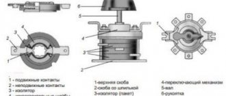
Design and principle of operation
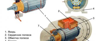
A standard contactor design includes several basic parts. The device consists of a housing (1), a control coil output terminal (2), a power contact terminal (3), a fixed magnetic core (4), a moving part - a core (5), a control coil (6), a short-circuited magnetic circuit ring (7), fixed and moving contacts (8 and 9), on-off indicator lever (10).
The coil is the main element that creates the magnetic current. If it is also used as a throttle, then with its help a driving force is generated that ensures the operation of the devices. The tension of the contacts is fixed using a contact spring. During docking, the moving and fixed contacts are connected to each other. They are constantly in motion and perform certain actions. Fixed contacts are fixed to the body, and movable contacts are connected to the core.
The contactor works as follows:
- After applying voltage to the control coil, the armature is attracted to the core. As a result, the contact group closes or opens, in accordance with the initial position of a particular contact.
- After turning off the power, all actions occur in the reverse order. The electric arc that occurs at the moment of opening is extinguished using an arc extinguishing system.
- After the voltage supply is stopped, the electromagnetic field disappears and ceases to hold the armature or core.
- The return spring moves the contacts to their original position, completely opening the circuit. Thus, the modular contactor performs its main work during periods of supply and shutdown of voltage.
What is the difference between a contactor and a magnetic starter
Very often contactors are confused with magnetic starters and this is justified, since in essence they are the same thing. These types of devices are structurally almost identical. The difference between these devices is in their purpose: if the contactor is a monoblock device, is a switch and mainly serves for switching circuits, then the electromagnetic relay (starter) also performs a protective function, for example, by emergency opening the circuit in case of overheating, and has several contactors, protective devices and control elements.
We recommend reading: How to make a tube headphone amplifier with your own hands
There is such a type of switching device as an intermediate relay - this is a low-power device that is used for switching in low-current circuits and can withstand many more opening cycles than a contactor.
Features of slot machines of some famous brands
Brands of switchboards for home and business electrical networks produce devices with memorable features. Before purchasing, you should clarify the features of the equipment:
- The Chinese brand "Energy" presents 2 series. 46-73 has no indicators or recesses, suitable for 6 kA current. VA 47-29 – with side recesses, double-sided comb, 6 kA.
- The manufacturer EKF offers devices from the Proxima line with plugs for seals. Budget machines 47-63 come without them.
- The products of the Kursk company KEAZ are easily distinguished by their place of production. Russian VM-63 are suitable for seals, combs, and have contact indication. Chinese VA 47-29 are rated at 4.5 kA, without indicators and holes for the comb.
- Heavy Hungarian GEs are designed for a current of 6 kA and do not have recesses on the sides. Comb area on one side.
- Polish Legrand TX switches for current 6 kA with recesses, but without indicators and combs.
- You can identify the place of production of Shneider Electric by its power. Bulgarian ones are suitable for current from 25 A, everything below is made in China. The Easy 9 series are good inexpensive single-pole models.
- ABB S series products (6 kA) have an indicator, notches, and a one-sided comb. SH switches (4.5 kA) come without combs and indicators, but with recesses.
Schemes for connecting magnetic starters
One of the simplest magnetic starter connection diagrams is shown below:
The principle of operation of this circuit is quite simple: when the QF circuit breaker is closed, the power supply circuit for the magnetic starter coil is assembled. The PU fuse provides short circuit protection for the control circuit. Under normal conditions, the thermal relay contact P is closed. So, to start the asynchronous machine, we press the “Start” button, the circuit closes, current begins to flow through the coil of the magnetic starter KM, the core is retracted, thereby closing the power contacts of the KM, as well as the block contact BC. The block contact BC is needed in order to close the control circuit, since the button, after it is released, will return to its original position. To stop this electric motor, just press the “Stop” button, which will disassemble the control circuit.
In case of prolonged current overload, the thermal sensor P will be triggered, which will open contact P, and this will also lead to the machine stopping.
When using the connection diagram above, you should take into account the nominal voltage of the coil. If the coil voltage is 220 V, and the motor (when connected in a star) is 380 V, then this circuit cannot be used, but can be used with a neutral conductor, and if the motor windings are connected by a delta (220 V), then this system is quite viable.
Circuit with neutral conductor:
The only difference between these connection schemes is that in the first case, the control system power is connected to two phases, and in the second to a phase and a neutral conductor. When automatically controlling the starting system, instead of the “Start” button, a contact from the control system may turn on.
You can see how to connect a non-reversible magnetic starting device here:
The reversible connection circuit is shown below:
This circuit is more complex than when connecting a non-reversible device. Let's look at the principle of its operation. When you press the “Forward” button, all the actions described above occur, but as you can see from the diagram, a normally closed contact KM2 appears in front of the forward button. This is necessary to electrically block the simultaneous activation of two devices (avoiding short circuits). When you press the “Back” button while the electric drive is running, nothing will happen, since the KM1 contact in front of the “Back” button will be open. To reverse the machine, you must press the “Stop” button, and only after turning off one device can you turn on the second.
And a video of connecting the reversible magnetic starting device:
Where and why is it used?
Most often, a modular contactor is used to control and switch a heating pump and other various devices (for example, in ventilation systems). They have become popular and in demand when assembling panels in apartments and various automation systems. For example, control of light, well pump, automatic reserve switching circuit, and so on. Why? Because the contactor fits perfectly with other modular devices, without disturbing the ergonomics of the switchboard. You can verify this by looking at the visual example in the photo:
It is worth remembering that the mains voltage should be no more than 380 Volts at a frequency of 50 Hz. But despite this, the contactor can operate at high powers. There are several other advantages of this device. Such as the almost complete absence of noise and vibration, which has a rather positive effect when used not only in a home panel, but also in public places (hospital, apartment, schools, institutes, etc.), since other switching devices are too susceptible to strong vibration.
By the way, size matters. After all, the small size of the modular contactor allows it to be installed on a DIN rail. The design includes arc-extinguishing chambers to extinguish the arc that occurs when the current load changes. In addition, there are single-phase and two-phase contactors, which allows you to connect to any network.
You can learn more about modular contactors by watching this video:
The contactor is modular. Description, application, parameters.
In this article we will talk about a modular contactor or, as it is often called, a magnetic starter or relay. When used correctly in electrical panel circuits, a modular contactor can be a very useful device, including indispensable when designing automatic transfer switches.
In my electrical panels, as a rule, I use a contactor to remotely (remotely) turn off/on consumers. For example, for controlling non-switchable lines in an apartment or private house, as well as for controlling heating systems in conjunction with the GSM controller “Xital” and other similar relays that can command the contactor to turn on or off remotely using GSM communication.
In production, contactors (magnetic starters) are usually used to control motors, pumps, and also in remote control circuits for many other devices and lighting.
Conventional modular contactor: what is it for?
A modular contactor is an electromagnetic electrical unit that can be controlled at a distance, in remote mode. Such devices are needed for switching or, in other words, connecting and disconnecting current in a circuit.
Such a contactor can use direct or alternating current for its operation, and also have from one to four poles of other contacts. Since this device is an electromagnetic device, the force for the connector and connection of contacts is created directly by the electromagnet.
Most often, a modular contactor is used to control the operation of heating pumps, various ventilation devices, and lighting devices. Helps in automation of building engineering equipment. It is also needed on the electrical panel in the apartment and when creating any automatic circuits.
This device has a number of advantages over other modular devices:
- Absolute noiselessness during operation;
- The presence of a built-in diode bridge capable of rectifying alternating current;
- Simple installation and ease of use;
- Ability to connect to any network;
- Using the device at high power;
- Compact dimensions allow it to be fixed to a DIN rail with a latch;
- It is possible to suppress interference that negatively affects the operation of the device.
Also, depending on the brand and type of device, it can be supplemented with various relays, sensors or other devices used in electrical engineering.
If you need to choose a good contactor or starter, then you should pay attention to companies such as Abb, TDM Electric (KM63 series) and others
Working principle of electromagnetic contactor
A contactor is an electrical device that is used to turn on and off AC and DC power circuits at a distance.
In normal mode, the operation of the contactor allows you to turn on and off power electrical circuits quite often - in some cases up to 1500 times per hour, which allows them to be used in the control of high-power engines, for example in electric locomotives, tram and trolleybus cars, diesel locomotives, elevators, etc. Today it is widely used AC contactors are used, most often three-pole devices, although there are also devices with two, four and five poles. Double-pole and single-pole DC contactors are used much less frequently.
Depending on the type of contact system drive, contactors are electromagnetic, pneumatic and hydraulic. Among all varieties, electromagnetic contactors are used as the main switching devices due to their versatility, wear resistance and efficiency. The operation of this type of contactor is based on the action of electromagnets.
How a modular contactor works (+ control circuit)
The principle of operation of a contactor of any model is that a group of movable contacts constantly converges and diverges from motionless fixed contacts, passing and limiting the flow of electric current. It may seem like a simple switch, but it has a number of features.
Lighting control circuit
First and most importantly, to ensure safety, the normal position of the contact groups (rest mode) is open. Such devices do not have any mechanical functions to influence the contacts so that they are always on. They close only when voltage is applied to them.
Note! Contactors are subject to special requirements for electrical safety, reliability and durability. Unlike simple switches, they have a higher quality of workmanship, which prevents emergency situations of various types.
Types of contactors
In terms of equipment with protective equipment: almost all models include a thermal relay unit, which opens the circuit of additional contacts in the event of current overload. In this sense, the operating principle of a magnetic starter is no different from a circuit breaker. After an emergency shutdown and cooling of the protective group (the power circuit of the electromagnet winding is restored), the power contacts do not close. It is assumed that the operator will eliminate the cause of the emergency and restart the electrical installation.
According to the method of closing contacts, there are the following types of magnetic starters:
- Direct connection, that is, with one group of power contacts. It works according to the principle: “on” or “off”, plus protection against overload or short circuit.
- Reversible connection. An electromagnetic starter of this type is equipped with two groups of contacts, with which you can combine power lines. For example, phase rotation for an asynchronous electric motor. When different groups of contacts are closed, the electric motor shaft rotates in different directions, that is, reverse occurs.
- Working only to close power contacts, or having normally closed and normally open contact groups. Such switches can control (in antiphase) two electrical installations. One device is connected, the second is simultaneously de-energized.
- By the number of power group contacts:
- Two contact (for single-phase consumers).
Three-contact (only phase groups are connected, the neutral is always connected). This is the most common starter model; you can connect both one and three phase electrical installations to it.
- Four or more contacts in power groups. By group we mean either a normally closed or normally open set. They are rarely used, only in special devices that operate according to a special connection scheme.
Most starters look like this:
Power contacts (three phases), additional ones are located in one plane to power the winding.
Or like this:
For ease of installation, additional contacts are placed on a separate platform, below and to the side.