Due to unstable voltage in houses and apartments, people are forced to install voltage stabilizers (hereinafter referred to as SV) to power the entire home or to operate a specific device. As with any other type of electrical appliance, sometimes a situation arises when the voltage stabilizer does not work (broken). Internal faults in most cases are associated with power circuits: relays, triacs, servo drive control unit, etc. Therefore, before you begin to analyze the malfunction and the cause of its occurrence, you need to understand what type of stabilizer you have failed. In this article, we will look at what types of voltage stabilizer malfunctions there are, why they occur, and how to fix them yourself (if possible).
Operating principle of rectifiers
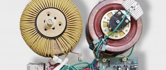
The operating principle of devices differs depending on their type, power and a number of other characteristics. The design of Resanta rectifiers includes the following elements:
- The electronic unit.
- Transformers of automatic type.
- Controls.
- Voltmeter.
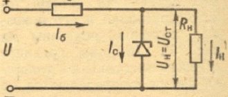
The schematic diagram of the Resanta 5000W stabilizer includes an electronic unit, which is responsible for controlling the operation of the power part of the unit.
The main module receives data on the power of the input voltage from the voltmeter, after which the automation checks the received figures with the established optimal values, making appropriate adjustments. The output is high-quality electric current with equalized amplitude. Voltage surges, which can damage operating equipment and household appliances, are completely eliminated. Depending on the type of transformer, the method of disconnecting and starting them, it is customary to distinguish two types of stabilizers:
- Relay.
- Electromechanical.
The most popular today are electromechanical type stabilizers, the design of which includes a servo drive that is responsible for turning off and starting the winding in the device.
The drive includes a low-power motor on which the contact brush is located. The advantages of electromechanical type stabilizers include their accuracy of operation, as well as a wide range of voltage adjustment. The only drawback is the complexity of the design, which negatively affects the reliability of the equipment. In relay stabilizers, built-in automation disconnects and connects the turns of the work switch until the optimal output voltage is obtained. To speed up the operation of the device, all turns of the transformer are divided into subgroups, which makes it possible to improve the voltage amplitude, while simplifying the operation of the device. Stabilizers of this type are reliable, which is explained by the simplicity of their design. The disadvantages include the low speed of voltage rectification, so it is not recommended to use them with sensitive devices.
Connecting the stabilizer to 380 V
If we consider the design of the unit, the three-phase stabilizer is made in the form of three single-phase devices, where each is responsible for stabilizing the single-phase voltage. Before starting installation work, you must carefully read the attached instructions and strictly follow all of its points.
Based on the connection method, three-phase stabilizers come in two types. The first type of equipment is characterized by three modules with three terminals, to which the wires are connected. The input and output of the “phase” and the neutral cable (input, three modules and the power circuit) are connected to the terminals. Each individual module is connected to a single-phase network.
The second type of unit also has three single-phase stabilizers, each with 4 terminals for connecting wires. In addition to the “phase” input and output, the “zero” input and output are also connected to them. This allows the neutral wire of the power input to operate separately from the neutral wire of the stabilized electrical network.
Three single-phase units or one three-phase unit can be connected to a three-phase network. Each option has its own advantages.
The first one has this:
- For each phase it becomes possible to select equipment of individual capacity;
- Based on operating conditions, a specific type of unit is selected for each phase;
- Three single-phase devices will be slightly cheaper compared to one three-phase one;
- Single-phase models are easier to transport;
- If service is required, only the device of the three that requires intervention is turned off.
The advantage of connecting a three-phase unit to a similar network:
A three-phase consumer is connected without any problems. However, there are certain disadvantages that should be taken into account: Stabilizers of this type are only electromechanical, and this can become a problem with frequent power surges; Difficulties in transportation. This is determined not only by their weight and dimensions, but also by the fact that they can only be transported in an upright position; It is impossible to distribute power across phases depending on the consumer.
There is no 220 Volt output
The malfunction manifests itself in the fact that the stabilizer does not produce a voltage of 220 Volts. This does not necessarily indicate internal problems, the reason may be the mains voltage - it is too low, and the device simply does not pull. If the power is in the operating range of the stabilizer, then we will proceed with the repair.
What to do:
in servo-driven models, failure may be caused by wear of the brush mechanism or the servo drive itself. It may not reach the end of the winding or the brush may not be in contact with its corresponding sector. In the simplest case, it may simply be contaminated with graphite. To repair it, you need to clean the surface of the contacts to a metallic shine. Sometimes you need to replace the brush.
Interesting!
It also happens that due to contamination of the working sector of the brush assembly with graphite, the voltage often does not rise above a certain value.
In relay MVs, this most often indicates that one or more electromagnetic relays or their control cascade is faulty. It is usually built on a transistor. Relays can have different coil voltages, often 12 volts.
What to do:
To check, apply voltage to the coil and ring the power contacts. They should close and open, the relay clicks. If this does not happen, either the contacts have stuck (more often), or the relay coil has burned out (less often). If the relay is working properly, check the transistor; it should not be broken, and the emitter-base and collector-base junctions should ring in one direction, like a diode. Use any low-power transistors of similar conductivity.
In triac and thyristor MVs, the fault diagnosis is similar - you need to test the semiconductor power switch for breakdown and, if it fails, replace it with an analogous or more powerful one.
Poor voltage stabilization
If the voltage stabilizes in too large steps, and before everything was smooth, then the breakdown is close to the previous one - the switching device has failed at one or more adjustment stages. The algorithm for checking voltage stabilizer malfunctions and their elimination are described in the previous paragraph.
Attention! The characteristics of each stabilizer describe either the adjustment step or the boundaries of each stage, as well as the accuracy of maintaining the rated output voltage.
In servo-drive stabilizers, this occurs when there is a breakdown in the engine gear mechanism, as well as when the windings are dirty, as was the case in the cases described above. Gearbox malfunctions may be accompanied by an uneven buzzing or crackling sound - this is the gears slipping.
What to do: you need to disassemble the mechanism and if all parts are normal, replace the lubricant.
It is also worth noting that servo-driven MVs may lack stabilization and may not work correctly due to the failure of the semiconductor motor control switches. Then the slider with the brush moves to one of the extreme positions or does not move at all.
Repair
Repair of the Resanta stabilizer can be divided according to the type of breakdown.
Servo
First, let's look at a situation where the Resant servo motor fails. There are two ways out of this problem:
- Buy a new motor, then install it in the device.
- Try to repair the damaged one.
If everything is clear with the first case, then the second requires detailed consideration.
It is important to understand that if the repair work is successful, the restored engine will not be able to work for a long time, i.e. this is a temporary measure
All our actions will boil down to the following:
- We disconnect the motor with the servo drive from the overall structure. Then we connect it to a power source with sufficient power.
- It is necessary to supply a current of 5 V to the motor outputs. The current must be at least 90 mA.
- Carrying out these manipulations will normalize the operation of the stabilizer. Next you need to connect the motor back to the circuit.
The circuit is quite simple: the input cable is connected to the input terminal, the neutral cable is connected to the neutral terminal. The same manipulations are performed for the output cables. In addition, you need to remember to connect the ground wire.
Relay
Failure of a relay often leads to breakdown of transistors. For example, in the ASN-5000 model, transistors of the D882P type are located. The diagram is shown below:
If these transistors fail, then you need to purchase new ones to replace them. You can purchase them quite freely, because many specialized stores sell Resanta brand equipment and components.
You can also try to repair damaged parts:
- First you need to remove the relay cover. Next, remove the moving contact, freeing it from the spring.
- Using sandpaper, remove all carbon deposits from the contact. We carry out this manipulation for both contacts - upper and lower.
- Then we lubricate the contacts with gasoline, after which we assemble the relay structure.
Other faults
Another possible problem is that the display turns on randomly, as well as the relay itself turns on. The reason for this may be the XTA1 resonator, which may have been soldered incorrectly.
The repair is as follows:
- Solder this resonator using a soldering iron.
- Use sandpaper to clean the leads.
- Solder the resonator back.
A specialist's story about the repair of Resant
The degree of difficulty of repairing various types of stabilizers
All devices are equipped with protection systems that determine the levels of input and output operating parameters to ensure their compliance with the nominal value. To carry out repair work, you must have measuring instruments, including an oscilloscope, and a circuit diagram of the device. It is necessary to measure the input and output voltage, the temperature conditions of the working units, exclude a short circuit, then look at the error code. The most difficult thing to diagnose is a failure in stabilizers equipped with triac switches - they are controlled by complex electronics. Measurements using an oscilloscope make it possible to identify a breakdown of a structural module, after which it is necessary to troubleshoot each radio component.
In relay-type devices, the relay that performs the function of switching the transformer windings most often fails. Due to frequent switching, the coil may jam or burn out, so if it breaks, it is necessary to check the functionality of all relays.
The simplest is to repair the electromechanical stabilizer - to see its reaction to changes in network parameters, just remove the housing. High precision and simplicity of design have made this type one of the most popular.
Stabilizer transformer overheating
If the transformer heats up without visible loads, there is most likely an interturn short circuit. However, the reason may also be due to broken switches.
In relay devices, the cause of overheating may be a jammed relay; in triac devices, one of the switches may break and short-circuit the output windings. In servo-drive stabilizers, there is no winding switching, but the brushes can short-circuit due to contamination - graphite filings or soot getting into the space between them. Servo-driven models require periodic cleaning of contact surfaces.
Repair and modification of servo stabilizers
The wear rate of the servo drive device and its contamination depend on two factors: room humidity and dust in the environment in which it is operated. To protect it from dust getting inside, the technician installs a computer cooler opposite the most used sector of the autotransformer. In addition to cleaning dust, the cooler performs the function of cooling the autotransformer.
Long-term storage of the stabilizer in a humid environment can lead to oxidation of the contact pads, which can interfere with the performance of the contact slider - dust can begin to spark and ignite.
Features of operation of an electromechanical device
First we will look at the electromechanical normalizer. The design of this voltage stabilizer provides for the presence of such an element as a servo drive. Actually, thanks to it, the different windings of the automatic transformer are switched.
Switching of these windings is carried out smoothly and as a result, precise regulation of the output voltage is ensured.
How does this smooth adjustment occur? A servo consists of a motor and a brush (electrical contact) that is attached to the motor's armature. When this anchor rotates, the brush also moves. It is constantly in contact with the copper windings of the transformer.
In fact, she glides along them. It has a width that allows you to connect two windings at the same time. As a result, no phase is lost at the output.
In order for the brush to move in a certain direction and by a certain amount, an error voltage is created in the normalizer. Further, thanks to the operational amplifier and the transistor output stage (it is a power amplifier), this voltage is amplified.
After this, it is supplied to the engine and causes the armature to spin in a certain direction.
The brush, which is in contact with the windings, also moves in this direction. The error voltage is proportional to a value that is the difference between the number of volts at the input and the required number of volts.
The error signal can have one of two polarities and as a result, each polarity causes the motor axis to rotate in a certain direction. These are the features of the operation of the electromechanical normalizer.
Note that many people buy a 10-kilovolt-ampere electromechanical stabilizer. Therefore, possible malfunctions and breakdowns of this type of voltage stabilizer will be considered on this model. Below is its electrical diagram.
Rice. 1. Electrical circuit of the ASN-10000/1-EM stabilizer.
It is worth paying attention to the fact that the general structure of all normalizers of this type is similar. The differences lie in individual elements of the models with different power levels
To increase the life of transistors and servomotor
Here's what Andrey writes:
I thought I could quickly solve the problem by installing a zener diode or a diode at worst, but the voltage levels are too low to make any difference. It is also possible to build something with a dead zone on transistors, but this is all a grandiose stucco on the board. Ideas swarmed in my head to insert a second op-amp and connect it to the break in the control circuit.
And then my father, looking over his shoulder, discovered in the diagram a completely unused (at least in the single-phase version) operational amplifier, already soldered on the board on legs 12, 13, 14 with output to pin 4XT2, which was simply hanging in the air. And then there were estimates of gain factors and feedback. As a result, this scheme was born. (picture based on one taken from the article).
Stabilizer circuit with response threshold
The threshold element is two back-to-back diodes connected in parallel. resistors R101 and R102 regulate the feedback and ultimately give the width of the dead zone. I settled on the 10k and 2.2k ratings which gives about 3V AC insensitivity. As soon as the voltage in the network changes to a larger value, one of the diodes opens and the electric motor is supplied not with a gradually increasing voltage, but immediately with a threshold, allowing the engine to immediately take a step. In addition, correction of the output voltage with a trimmer was required to set the output voltage. Well, with the second file I’m attaching what the printed circuit board looks like after modification.
Stabilizer printed circuit board after modification
Yes, in the original circuit, instead of a motor, I connected a small light bulb and a voltmeter. The tension gradually increases in either direction. In my circuit, the motor turns on when there is already a more serious voltage deviation. Moreover, if the voltage suddenly jumps in either direction, there will be no delays in operation.
Refinement affects accuracy, but in real life it does not matter much. The output voltage in my case has the right to vary +- 3 volts from the set nominal value. This is an inevitable price to pay for less nervousness of the servo. You can increase the gain of the first op-amp (blue text in the diagram) and get +- 1.5 volts.
There is one more moment. All experiments were carried out on a stabilizer in which the motor was replaced with a more expensive version with graphite brushes. It was not possible to check how it will spin with a standard motor.
The machine does not turn on or crashes after the timer report
Most stabilizers do not enter operating mode immediately after switching on, but after a temporary delay. But after the report, the start-up timer does not occur, and the display indicator shows the letter N. An example of repairing a device with such a malfunction is discussed in the following videos:
For your information, the error code “H” indicates that the network voltage is too high and the protection has tripped. This is valid for devices, "Luxeon" and some others.
Interesting:
the letter “H” means “High” or “High”, and L means “low”, “Low”. The resistor, the replacement of which you saw in the video, is responsible for the response thresholds for the upper and lower voltage levels. Due to incorrect resistance, the stabilization board cannot do its job and goes into protection.
Such symptoms or another malfunction code may be accompanied by the breakout of the circuit breaker supplying the stabilizer itself after the turn-on delay timer reports. In this case, the problem is solved by replacing the relays, which, if stuck, may result in increased current consumption.
Components of three-phase Resanta ASN
Before moving on to repairing the voltage stabilizer, let’s first take a brief look at what our box consists of and how it works.
So, as I already said in the previous article about three-phase stabilizers, a three-phase stabilizer is three single-phase ones. The same is the case with Resanta asn-20000/3-em:
Three-phase electromechanical stabilizer - device
It can be seen that this stabilizer consists of three identical parts - three single-phase stabilizers, each of which stabilizes only its own phase. This applies to such common single-phase models as ASN 10000 1 em, etc.
That is, even if there is a significant imbalance in the phase voltages at the input, the output for all phases will be 220 V + -3%. You can read more about the parameters of such stabilizers in the instructions, which can be downloaded at the end of the article.
And if the phase imbalance occurred as a result of a zero break, about the consequences of this. A three-phase stabilizer will correct the situation to a certain extent, and if it fails, it will turn off and save the consumer.
Autotransformer
The heart of an electromechanical transformer is a step-up autotransformer. This “heart” beats in time with the change in voltage at the input of the stabilizer, trying to equalize it to normal.
Step-up autotransformer - the heart of the electromechanical stabilizer
Why is a step-up autotransformer used rather than a step-down autotransformer? Because stabilizers most often have to deal with reduced input voltage. But this does not mean, of course, that it cannot reduce the overestimated input voltage. However, I will not describe the principles of operation of the autotransformer here.
Let's look at the stabilizer device in the following photo:
Stabilizer device with explanations
The first thing you need to understand is that an autotransformer consists of two equal parts connected in parallel to increase power. Accordingly, there are two windings, two brushes ride on them (the brush is not visible in the photo, it is indicated by an arrow).
Since the brush is a contact, and a rather poor one at that, it gets hot. This is normal, but a radiator is provided to cool it. A temperature sensor is installed in the brush radiator, which, when the permissible temperature is exceeded (105°C), opens the control circuit and disconnects the load from the stabilizer output.
The motor moves brushes along the surface of the winding, adjusting the voltage. At the end of the brush stroke, corresponding to the lowest voltage (140 V), limit switches are installed to stop the motor. This is the most difficult operating mode, since the output power of the stabilizer drops. If the voltage drops further, the autotransformer can no longer cope, and the entire stabilizer turns off. This occurs by opening the KL relay contacts (see circuit diagram below).
A temperature sensor is attached (glued) to the transformer body, which, when overheated above 125 °C, opens the control circuit, protecting it from further thermal destruction.
Both types of sensors are self-healing. That is, when it cools down, the control circuit is assembled, and the stabilizer is ready for use again.
Electronic board
What makes the autotransformer motor move? This is an electronic circuit that measures the input phase voltage and outputs voltage to a servo motor, which moves the autotransformer brush, changing the output voltage to the desired level:
The above photo shows the consequences of eliminating a common malfunction - breakdown of bipolar power transistors through which the engine is controlled. Along with them, resistors also burn out, which initially had a power of 2W, but were replaced by 5W. But for malfunctions and repairs - at the end of the article.
This starter is necessary to protect (turn off) the stabilizer and load in case of unavailability, malfunction or overheating.
Maybe this will be interesting too?
Let's take a closer look at its operation when analyzing the electrical circuit diagram.
Electrical diagram of a three-phase voltage stabilizer Resanta
Let's consider the circuit of a single-phase electromechanical stabilizer Resanta ASN - 10000/1-EM. Let's take this circuit, because, as I said, three single-phase ones are one three-phase stabilizer.
The diagram, as usual, can be zoomed in and then enlarged to 100% by clicking on the arrows in the lower right corner of the image. Then right-click, Save Image As... etc.
Be sure to check out how to print such a large diagram.
Electrical diagram of voltage stabilizer Resanta-ASN-10000-1-em
For ease of perception, I have marked the main structural parts on the diagram.
I will not fully consider the operation of electronics; if you are interested, ask questions in the comments.
Now - how does this circuit differ from the circuit of a three-phase stabilizer:
The main difference is in the control circuit. In the single-phase version (in the diagram) it can be seen that the control circuit for powering the KM starter is assembled as follows: Neutral – On-delay relay KL – Thermal relay 1 transformer (125°C) – Thermal relay 2 transformer (125°C) – Thermal relay 1 brush (105 °C) – Brush thermal relay 2 (105°C). Total – 5 contacts. If this circuit is assembled, the KM contactor turns on and voltage is supplied to the output of the stabilizer.
In the three-phase version, in order for the stabilizer to start, 15 (!) conditions must be met - this is exactly how many contacts must be closed in order for the KM contactor to turn on.
During normal operation, when the stabilizer is turned on, you can hear how the CC is assembled - after about 10 seconds there is a click (on one of the electronic boards), then another one, and the third click starts the contactor and the entire stabilizer.
What is a control circuit, its difference from emergency and thermal circuits, and why the repair of any serious automation must begin with checking the control circuit - it is described in detail, I highly recommend it if you have read this far)
The second is the absence of a cooling fan; in this case, the cooling is natural.
Third, there is no bypass; its implementation will require the use of a three-pole contactor with normally closed contacts (or two conventional contactors), this is expensive, so the manufacturer did without it.
I am also writing to the house about this problem via AVR.
Stabilizer testing method
A clear sign of a malfunction of any stabilizing device is the absence of voltage at its output terminals, while it is present at the input terminals. In this case, the device is automatically recognized as broken and in need of repair.
More detailed diagnostics can only be carried out by a qualified specialist in an electrical laboratory. To ensure correct stabilization, it is necessary to simultaneously monitor the voltage at the input and output of the device with measuring instruments. The voltage at the load, regardless of the supply voltage, must lie in a narrow range - 220-230 V. That is, no matter how many volts arrive at the input of the stabilizer, the voltage at the output must remain unchanged. Moreover, this is true both for operation of the device in idle mode and with a consumer connection.
220 V at the output of the stabilizer
Damage diagnostics
Inverter voltage stabilizer
Repair of voltage stabilizers begins with an assessment of its feasibility. If the voltage at the output of the device is zero, this does not mean that the problem lies with it. Perhaps the voltage does not reach the stabilizer itself, so the first thing you need to do is make sure it is present at the input terminals. This can be done using any voltmeter or 220 V light bulb.
If this is not the problem, then you should remove the stabilizer cover. First, it is strictly necessary to turn off the input circuit breakers and make sure that there is no voltage coming to the device. Then you should inspect the stabilizer for burning of the control board tracks, darkening of the wires, relays and their contacts, or destruction of the graphite brushes.
Burnt track
It would be a good idea to take a sniff. If you smell a burning smell, you should, if possible, find out its source. Often this is a direct indication of the cause of the breakdown.
Basic faults
Voltage stabilizers from the Latvian company Resanta have proven themselves to be quite reliable and high-tech.
However, they can also break. Due to the design features of relay and electromechanical devices, there are characteristic breakdowns that require replacing damaged elements and restoring the functionality of the equipment. For electromechanical stabilizers, the drive may break down, which bears an increased load during operation of the device. In electrical networks where there are frequent power surges, the electric motor may break down within a year of using the equipment.
DIY voltage stabilizer
To collect all the necessary elements, you will have to go to the store, but you can try to make some parts yourself.
Manufacturing of transformers
This primarily applies to devices T1 and T2. To produce T1, the power of which should be 3 kW, a magnetic core with a cross-section of 1.87 cm2 is required, as well as three PEV-2 conductors. The diameter of the “first of the last” should be 0.12 mm (section - 0.064 mm2). It is used to create the primary winding, the number of turns is 8669. The rest are used for other windings, the diameter of both wires is 0.185 mm. The number of turns is also the same - 552 each.
An alternative is to use a pair of ready-made transformers - TPK-2-2×12V, they are connected in series:
Transformer T2 must have a power of 6 kW. For its manufacture, a toroidal magnetic circuit is used. For the winding they take the same PEV-2, the number of turns in this case is 455. 7 taps are made here. For the first three you need a wire with a diameter of 3 mm. The remaining 4 require tires with a cross section of 18 mm2. The goal is to prevent the transformer from heating up. Bends are made at 203, 232, 266, 305, 348 and 398, counting from below. The current from the network must pass through the tap at the 266th turn.
What else will you need to buy?
All other items must be purchased in the store. The set includes:
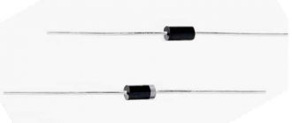
- triac optocouplers MOC3041 - 7 parts;
- triacs BTA41-800B - also seven;
- 2 diodes DF005M (VD1 and VD2) and comparator LM339N (for DA2, DA3);
- stabilizer KR1158EN6A (DA1), fuse switch;
- capacitors: 4 oxide (for C1-3, C-5), the same number of film or ceramic (C4, C6-C8);
- resistors with different tolerance percentages: 7 pieces C2-23 for R16-22 with 1%, 30 any with 5%;
- 3 wirewound resistors for R13-14, R25 - SP5-2 or SP5-3;
- 7 current limiting resistors (16 mA) - for R41-47.
The KR1158EN6A stabilizer is mounted on a heat sink. An aluminum plate is used for this purpose. Its area is more than 15 cm2. Triacs are installed on it. All elements can be mounted on one heat sink, but it must have a fairly large cooling surface. Its area is at least 0.16 m2.
You will also need to purchase a KR1554LP5 microcircuit; it will “perform the duties” of a microcontroller. You need to purchase 9 flashing LEDs, but you can also buy regular ones that produce bright red light: for example, AL307KM or L1543SRC-E. There are usually no difficulties with purchasing parts, and spending on them can be considered a reasonable investment that will soon pay off.
Hum and clicks
If the voltage regulator is humming a lot, you need to check that the supply voltage is not above or below the permissible ranges. The adjustment range in most cases lies within 100-250 Volts.
Attention! Even when in good condition, the autotransformer hums evenly and not too loudly. The servo drive also makes a hum when moving the brush assembly.
Relay voltage stabilizers make clicking noises during operation. This is normal, the relays (black rectangles in the picture below) switch taps from the windings to regulate the output voltage.
If the device makes a loud noise, this may indicate sparking of the brush in servo-driven models, problems with the relay, and poor contact of the internal wiring of the device.
Shuts down under load
The voltage stabilizer does not support the load - this problem happens for a number of reasons. The first among them is increased load (consumer power). If you have not changed the connected devices, then the problem is in the stabilizer. If it does not turn off instantly, but after some time of operation, then this may be due to overheating or interturn short circuits of the autotransformer.
What to do: disassemble the device and carry out an external inspection of the windings of the autotransformer; if it is not too dusty, then check for signs of local overheating. If there is a lot of dust, clean it out
If there are signs of overheating and burning, the insulation of the windings is damaged. This is an interturn short circuit, then how to repair the stabilizer in this case? It is necessary to rewind or replace the autotransformer with one of the same or greater power. But the cost of such repairs can be comparable to purchasing a new voltage stabilizer.
Important! In servo-drive models, a number of malfunctions can be caused by brush wear and contamination of live parts with graphite shavings. During operation, the brush wears off, covering the autotransformer with graphite. Because of this, short circuits between current collectors and sections of turns and overheating can occur. In this case, you need to sweep away the graphite and clean it between turns. Make sure that the windings are laid evenly and there are no breaks. Clean the contact surface with a regular office eraser until it shines, especially the most used sector.
Servo drive of the device
In ultra-sensitive electromechanical stabilizers, the servo drive responsible for moving the contact brush most often fails. There are two types of solutions to this problem:
- Installation of a new electric motor.
- Repair of damaged elements.
The cost of servos for Resanta stabilizers is extremely high, so a complete replacement of the motor is resorted to only in case of serious damage, when it is impossible to repair it.
Do-it-yourself voltage stabilizer repair is carried out according to the following algorithm:
- The stabilizer housing is opened and the motor with the servo drive is turned off.
- The motor is connected to a power source with the required power.
- An electric current (5 W and not less than 90 mA) is supplied to the motor output.
The operation of the servo drive should be restored, after which the motor is installed in place.
https://youtube.com/watch?v=9AKAPf-V95s
If there is mechanical damage, it is necessary to open the failed motor and replace the burnt out drive elements. Such breakdowns are often observed when the servo drive is overvolted, when stabilizers are used in an electrical network with unstable voltage levels.
Problems with the engine may occur due to the failure of the electronic board through which electricity is supplied to the motor from bipolar transistors. Failed transistors should be replaced in pairs, since a bipolar power supply circuit is used. 10-ohm resistors can also burn out in the circuit, which can be replaced with similar ones or those with a power of 3-5 W more. In the latter case, the reliability of the servo drive increases and problems in equipment operation under peak loads are solved.
Relay damage
If at the stage of diagnosing the voltage stabilizer a faulty relay was identified, then the best thing that can be done is to replace it with a new one. This will be much more reliable. However, if a decision is made to repair the relay, then this should be done according to the following algorithm:
- You need to test the relay coil with a multimeter. If it is broken, then it needs to be rewinded (here again you need an electric winder).
- If the coil is working properly, then the relay should be disassembled. This must be done extremely carefully so as not to damage its contents.
- When the device is disassembled, the contacts are inspected for melting, burning or darkening. If there are any, they should be removed with a needle file or a thin nail file. Anything will do, just to remove carbon deposits and unevenness.
- Voltage is then applied to the relay coil to ensure that its normally open contacts move and connect. Reliability of operation must be checked with an ohmmeter. The contact resistance should be close to zero.
- Afterwards the relay is assembled. If possible, it is tested under load for a couple of hours and, if the tests are successfully completed, it is returned.
Basic faults
From the principle of operation of the electromechanical stabilizer described above, it becomes clear that when the current in the electrical network changes, the motor armature rotates simultaneously and the graphite brush moves.
The constant movement of the servo drive is the main weakness of the electromechanical device. Why? Because as a result of friction of the brush against the coil turns, excessive heating occurs both of the brush and the turns under it.
In addition, friction causes wear on the brush and contamination of the copper wires. The last reason causes sparks to appear.
Considering the fact that in our power lines the current changes very often, the servo drive moves with the same frequency. Such frequent rotation causes failure of the engine itself.
A notable feature is that engine failure causes failure of other parts. Thus, there is a possibility of failure of the engine control output stage.
Experts assemble this cascade based on a pair of transistors Q2 TIP41C and Q1 TIP42C. When these transistors burn out, resistors R45 and R46 also burn out.
They are components of the collector circuit of the above transistors. R45 and R46 are characterized by a resistance of 10 ohms and a power of 2 watts.
When there are such malfunctions, it is necessary to check the linear stabilizer. Its Latvian specialists assemble it on the basis of a zener diode DM4 and a transistor Q3 TIP41C.
If all these components of the electrical circuit of an electromechanical type voltage stabilizer, manufactured by, are burned out, then in any case they need to be purchased and replaced.
Repair of electromechanical stabilizer ASN-10000/1-EM
The electrical circuit diagram of the ASN-10000/1 EM stabilizer is shown in Fig. 1, the printed circuit board of the controller of this stabilizer is shown in Photo 1.
The operating principle of electromechanical stabilizers is based on smooth and precise regulation of the output voltage. The voltage change occurs due to the sliding of the electrical contact along the winding of the autotransformer using an electric drive. The stabilizer generates an error voltage, which is amplified by the operational amplifier and transistor output stage (power amplifier), and then it is supplied to the motor. Depending on the polarity of the error signal, the motor axis rotates in one direction or another. A slider is attached to the motor axis, which moves along the winding of the autotransformer, thereby normalizing the output voltage.
Let's consider one typical malfunction that occurs during the operation of electromechanical stabilizers, using the example of ASN-10000/1-EM and methods for eliminating it.
There is no output voltage stabilization.
The output voltage level can be different and remain unchanged. There is a smell of overheated components. The “Achilles heel” of electromechanical stabilizers is the reversible motor. The stabilizer controller constantly monitors the output voltage level. As a result, the engine rotor is in almost constant rotation, which leads to premature engine wear. After stopping the engine, the output stage of the motor control, assembled on the complementary pair of transistors Q1 TIP42C and Q2 TIP41C, may fail. In addition to these transistors, resistors R45 and R46, included in their collector circuit, burn out due to overheating. Their resistance is 10 Ohms and their power is 2 W. It would also be a good idea to check the linear stabilizer assembled on transistor Q3 TIP41C and zener diode DM4.
Of course, a worn-out engine requires replacement, but if replacement is not possible, you can try to restore it.
One of the simple ways to resuscitate a faulty engine is as follows: • disconnect the engine from the circuit; • apply a constant voltage of 5 V to its pins from a powerful power source, for example from an ATX computer power supply.
In this case, small particles of “garbage” are annealed on the motor brushes. Normal motor current consumption should be within 90...160 mA. Since the motor is reversible, voltage must be applied to the motor twice with polarity reversed. After these simple manipulations, engine performance is temporarily restored.
Principle of operation
Like all voltage stabilizers, the Resanta brand normalizers consist of:
- automatic transformer.
- electronic unit.
- voltmeter.
- element that connects/disconnects certain windings.
Considering that the manufacturer produces various types of stabilizers, the elements for connecting the windings are different. We will mention them below, namely when we consider the features of the operation and repair of each type of normalizer from the Latvian manufacturer.
The electronic unit of any stabilizer controls the entire operation of the device. It controls the operation of the voltmeter and receives data on the input voltage level. Then he compares this voltage with the normalized one and determines how many volts need to be added or subtracted.
After this, it is determined which stabilizer windings need to be connected or disconnected. When this information is known, the electronic unit connects/disconnects the necessary windings using a relay or servo drive and our electrical appliances receive a normalized current.
This principle of current stabilization is inherent in every voltage stabilizer from. However, the stabilization process differs in different models of the company. They are due to the fact that the transformer windings are connected/disconnected differently.
The company produces two types of stabilizers:
- Electromechanical.
- Relay.
And, of course, the repair of each of them has its own characteristics.
Series "ASN-N/1-C"
We noted earlier that the company also produces stabilizers that can be mounted on a wall. All of them are united under the category “ASN-N/1-C”. This series is better known under another name, namely “LUX”.
As part of this series, stabilizers are produced, the power of which ranges from 500 watts to 12 kilowatts. Of course, they differ from the representatives of the line described above in a different design of the case.
In other words, the Resanta wall-mounted voltage stabilizer, the technical characteristics of which do not differ from the characteristics of floor-standing models, boasts the presence of:
- Wall-mounted version of the case.
- Special fastening
- Expanded display.
Causes of breakdowns
The main cause of malfunction of the Resanta 10000W voltage stabilizer is improper operation of the equipment.
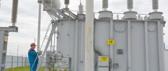
Quite often, overheating of rectifiers is observed when using equipment in a dusty room. Dirt settles inside the case, which impairs the cooling of the device, and problems arise with overvoltage of the power part and execution boards. Also, the cause of breakdown of electrical rectifiers can be operation in conditions of high humidity. The contacts and boards begin to oxidize, the connection deteriorates, which ultimately leads to serious damage to the stabilizers - they can be restored by replacing the servo drive or power elements.
In the stabilizer operating instructions you can find all the recommendations for using the equipment, which will help prevent the occurrence of typical breakdowns and the need for expensive and complex equipment repairs.
In the Resanta line you can find both simple and inexpensive household models that are intended for indoor use, as well as specialized industrial installations that can be used in conditions of high humidity and dusty, contaminated workshops. By choosing the right stabilizer, you can guarantee trouble-free operation and no breakdowns even under increased load.
Shows no signs of life or other damage at all
The most frightening malfunction is when, after applying voltage, neither the indicators light up nor the output voltage appears, i.e. when the voltage stabilizer does not work at all. In this case, the control board may fail. Most often, repairs begin with a visual inspection, paying attention to:
- burnt out paths;
- swollen electrolytic capacitors;
- burnt, cracked or exploded board components;
- microcracks on soldered contacts and cold soldering.
All identified deficiencies are eliminated, and if the external inspection does not produce results, they proceed to checking the board for broken tracks and short circuits with a multimeter in resistance and continuity measurement mode. Such repair of a stabilizer may require deep knowledge of electronics, electrical circuit diagrams, and in the most difficult cases, the use of an oscilloscope to check control signals and the logic of the circuit.
That's all we wanted to tell you about voltage stabilizer malfunctions and how to fix them yourself. We hope that now you know what to do in this or that case and why breakdowns occur!
It will be useful to read:
- How to use a multimeter
- What to do if the network voltage is low
- Dishwasher malfunctions
Resanta voltage stabilizers are used in many homes to ensure stable operation and protect the “health” of electrical appliances. As a result, home appliances work for a long time and undergo almost no repairs.
It must be said that the voltage stabilizer itself also requires compliance with operating conditions and periodic maintenance. Otherwise, the device may fail and require repair. In addition, after serving for a sufficiently long time, the device may break down simply due to wear and tear of parts.
This article is devoted to the delicate points of the Resanta brand stabilizers. Let's look at how failed parts are repaired and the device is restored to full functionality.
Servo motor repair
When the engine itself burns out, there are two options:
- Buying a new one and installing it.
- An attempt to restore an old engine.
The second option makes it possible to revive the engine on your own, however, not for a long time. For resuscitation, you need to disconnect the engine from the general circuit. After this, it must be connected to a powerful power source.
Your task is to supply current to its outputs with a constant voltage of 5 volts. The current should be between 90 and 160 mA. When such a current is supplied, every small particle of “garbage” burns out on the motor brushes.
Helpful advice: since the motor is of a reversible type, the polarity must be changed when applying voltage. This procedure is carried out twice.
After such actions, the engine will be able to work again, and the stabilizer will perform its main function. Next, according to a simple diagram, you can carry out the procedure for connecting the voltage stabilizer released.
This circuit involves connecting the input phase and neutral cables to the input phase and neutral terminals, respectively. The connection of the output wires is similar. A grounding wire must also be connected.
Another connection diagram for a single-phase stabilizer
There is also a connection diagram via a three-position switch.
It is also called reversible or reversible. It is also available in a modular version. The Internet describes a connection diagram using a single-pole three-position switch.
Do you need to remove the stabilizer? We put the reversing switch in the neutral position or turn off the input circuit breaker. Disconnect the stabilizer from the cable. We turn on the input machine, raises the reversing switch flag to the upper position. The consumer circuit (house, apartment) is powered.
But the phase voltage remains on the cable core that goes to the L out terminal of the stabilizer. This is not very convenient. Naturally, it is necessary to insulate the cable cores.
It is necessary to de-energize this cable core. For this we use a reversible double pole switch.
It turns out this is the connection diagram via a two-pole reversing switch.
When the circuit is turned on, both wires of the cable that goes to the stabilizer at terminals L in and L out are directly de-energized. This, you see, is much safer than in a single-pole reversible circuit.
We remove the stabilizer and supply power to the circuit. The house is powered. The cable that goes to the stabilizer is de-energized. We carry out the necessary manipulations with the device. It would still be a good idea to insulate the cable cores; they even need to be insulated.
What is good about this circuit is that anyone who can hold a screwdriver in their hands can disconnect and connect the voltage stabilizer. The main thing is to correctly perform the sequence of manipulations.
The cable must have a cross-section no less than that of the input cable to the meter.
Choose a device with a bypass. It's comfortable. Bypass we turn on the power without stabilization process, bypassing the circuit. Bypass can be used if the connected power is higher than the power of the stabilizing device. It is also advisable to turn on the bypass when working with a welding machine.
Now let's look at how to connect a three-phase voltage stabilizer to a three-phase network.