Simple parametric voltage stabilizer
The input voltage Uin must be significantly higher than the stabilization voltage of the zener diode VD1. And so that the zener diode does not fail, the current through it is limited by a constant resistor R1. The output voltage Uout will be equal to the stabilization voltage of the zener diode, but with the output current the situation is more complicated.
The fact is that each zener diode has a certain range of operating current through it, for example, the minimum stabilization current is 5 mA, and the maximum is 25 mA. If we connect a load at the output of such a stabilizer, then part of the current begins to flow through it.
And the maximum value of this current will depend on both resistance R1 and the minimum stabilization current of the zener diode - the maximum load current will be reduced by the minimum stabilization current of the zener diode. That is, it turns out that the lower the resistance R1, the greater the current that can be supplied to the load. At the same time, the current through R1 should not be greater than the maximum stabilization current of the zener diode.
Rice. 1. Circuit of the simplest parametric stabilizer using a zener diode and a resistor.
Since, firstly, the zener diode needs a certain margin to maintain the output voltage stable, and secondly, the zener diode can fail if the maximum stabilization current is exceeded, which can happen when the load is turned off or it is operating in a mode with low current consumption.
A stabilizer according to this scheme is very ineffective and is suitable only for powering circuits that consume a current not exceeding the maximum current of the zener diode. Therefore, stabilizers according to the circuit in Fig. 1 are used only in circuits with a small load current.
The principle of operation of the stabilizer
One part of this equipment is responsible for comparison with the reference value, and the other controls the parameters. If the input parameter is greater than the required indicator, the system reduces it. If the value is less, then the characteristics increase. The water in the tap is regulated using the same scheme: when the flow is less than necessary, the valve is turned on and vice versa.
The principle of stabilization is used on a wide variety of equipment, from irons to the space industry. The difference lies only in the technology for monitoring and managing indicators.
Important! According to existing GOST, the network voltage can vary within up to 5%, and in real conditions, 10% of the specified value. For high-quality operation of the equipment, this figure cannot exceed 0.1%.
The simplest voltage stabilizer circuit contains only 2 elements:
- reference voltage source – zener diode VD1;
- ballast resistor R1.
A zener diode is a diode that, at certain values of the stabilization voltage (reversely applied), begins to pass current in the opposite direction. If the voltage increases, while the internal resistance decreases, the zener diode continues to maintain the voltage at the set value. The operating principle can be seen in the voltage stabilizer diagram.
Scheme and schedule of stabilizer operation
If the reverse voltage increases, then the zener diode resists, which means the output current is minimal. When the specified parameter is reached, the current begins to increase. Then, reaching point 1 on the current-voltage characteristic, the voltage stops growing, despite the increase in current values. At the pn junction, the voltage increases only across the resistor, the zener diode operates in the specified mode. Of course, any zener diode can only hold the voltage at a given value, and after increasing the indicators to point 2, the element may begin to heat up and fail. The distance between points 1 and 2 is called the working area.
This simple stabilization method is only suitable for networks that use low currents. In order to increase the load capacity, an emitter follower in the form of a bipolar transistor is used. This element repeats the applied voltage. Due to this, the load can be an order of magnitude greater. You can use a circuit of several transistors, then the load will increase even more.
When creating such circuits, it is important to take into account that due to the drop in the pn junction section, the output voltage will decrease. Therefore, it is necessary to select a zener diode taking into account transition losses on transistors. In the figure in the circuit with two transistors you can also see another resistor. It is used to eliminate the reactive component of the second transistor.
Two simple stabilizers
Voltage stabilizer using a transistor
If you need to provide a more or less significant load current and reduce its effect on stability, you need to enhance the output current of the stabilizer using a transistor connected according to the emitter follower circuit (Fig. 2).
Rice. 2. Circuit of a parametric voltage stabilizer using one transistor.
The maximum load current of this stabilizer is determined by the formula:
In = (Ist - Ist.min)*h21e.
where Ist. is the average stabilization current of the zener diode used, h21e is the current transfer coefficient of the base of transistor VT1.
For example, if we use a KS212Zh zener diode (average stabilization current = (0.013-0.0001) / 2 = 0.00645A), a KT815A transistor with h21 e - 40), we can get no more current from the stabilizer according to the circuit in Fig. 2: ( 0.006645-0.0001) * 40 = 0.254 A.
In addition, when calculating the output voltage, you need to take into account that it will be 0.65V lower than the stabilization voltage of the zener diode, because the silicon transistor drops about 0.6-0.7V (approximately take 0.65V).
Let's try to calculate the stabilizer according to the diagram in Figure 2.
Let's take the following initial data:
- Input voltage Uin = 15V,
- output voltage Uout = 12V,
- maximum current through the load In = 0.5A.
The question arises, what to choose - a zener diode with a large average current or a transistor with a large h21e?
If we have a KT815A transistor with h21e = 40, then, following the formula In = (Ist -Ist.min) * h21e, we will need a zener diode with a difference between the average current and the minimum current of 0.0125A.
In terms of voltage, it should be 0.65V greater than the output voltage, that is, 12.65V. Let's try to find it from the reference book.
Here, for example, is a KS512A zener diode, its stabilization voltage is 12V, the minimum current is 1 mA, the maximum current is 67 mA. That is, the average current is 0.033A. In general it is suitable, but the output voltage will not be 12V, but 11.35V.
We need 12V. It remains to either look for a 12.65V zener diode, or compensate for the lack of voltage with a silicon diode, connecting it in series with the zener diode as shown in Figure 3.
Fig.3. Schematic diagram of a parametric voltage stabilizer, supplemented with a diode.
Now we calculate the resistance R1:
R = (15 -12) / 0.0125A = 240 Ohm.
A few words about choosing a transistor based on power and maximum collector current. Maximum collector current Ik.max. must be no less than the maximum load current. That is, in our case, no less than 0.5A.
And the power should not exceed the maximum permissible. You can calculate the power that will be dissipated by the transistor using the following formula:
P = (Uin - Uout) * Iout.
In our case, P = (15-12)*0.5=1.5W.
Thus, Ik.max. transistor must be at least 0.5A, and Pmax. at least 1.5W. The selected transistor KT815A is suitable with a large margin (Ik.max.=1.5A, Pmax.=10W).
Switching stabilizers
Voltage stabilizer 12 volts
In addition to compensation and parametric stabilizers, there are pulse circuits in which the efficiency is the highest, even if the input voltage range is quite large. The operation of these devices is based on the fact that the control element is switched off and on in a pulsed mode. The general circuit of the stabilizer consists of a key, an energy storage device and a control circuit. The drive and the key together represent the power part, together with the circuit they make up the control loop.
A switching voltage stabilizer can be assembled using 3 transistors. In this case, VT1, VT2 constitute a key regulatory element, and VT3 is necessary to amplify the mismatch signal.
Switching stabilizer circuit
The operating algorithm is as follows:
- From the collector VT2 through capacitor C2, a positive feedback voltage is supplied to the base VT1;
- VT2 opens when saturated with current from resistor R2;
- At the collector-emitter junction, when VT1 is saturated, it is less than the voltage for opening VT2, which means when VT1 is open, VT2 is closed;
- The amplifier on VT3 is connected through the emitter to the zener diode VD2, and the base is connected to the output voltage divider R5, R6, R7;
- Thus, VT1 controls the closing and opening of VT2 based on a signal from VT3;
- When VT2 is open, energy accumulates in the throttle; after closing, the energy goes to the load.
Each of the presented schemes will allow you to assemble the simplest version of stabilizers.
A simple powerful parallel transistor stabilizer
This article describes the principles of operation of a parallel stabilizer, and discusses the possibility of its use for stabilizing the power supply of powerful high-quality low-frequency amplifiers. A diagram of a complete power supply with a parallel stabilizer is also shown.
Parallel stabilizers are widely used among radio amateurs, as well as in high-quality industrial audio devices. In these devices, the stabilizing element is connected in parallel to the load, which has a good effect on such a parameter of the stabilizer as its performance. In fact, the speed of the stabilizer is determined by the speed of the stabilizing element. Also among the advantages of parallel stabilizers is the fact that regardless of the current consumed from the stabilizer, the current consumed by it itself from the power source remains unchanged. This fact has a positive effect on the level of noise emitted by the power supply as a whole (due to the fact that deviations of the consumption current do not flow through the transformer and rectifier bridge), although it is the reason for their low efficiency.
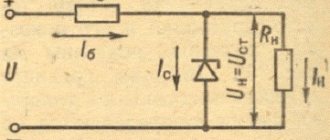
Let's consider the above using the example of the simplest parallel stabilizer - a parametric stabilizer on a zener diode (Fig. 1.)
Fig.1. Parametric stabilizer
Resistor R0 sets the total current that will flow through the zener diode and the load connected in parallel to it. It is easy to see that when the load current changes, the current through the resistor R0 will remain constant, only the current flowing through the zener diode D1 will change. This will happen as long as condition (1) is met: IHR0-Ist.min. (1) where IN is the load current, IR0 is the current through R0, Ist.min. – minimum stabilization current of zener diode D1
The performance of this stabilizer will be determined mainly by the rate of change in the value of the barrier capacitance of the zener diode [1], as well as the charge-discharge time of capacitor C1. However, such stabilizers also have disadvantages - in particular, to obtain a more or less decent stabilization coefficient (>100), a current commensurate with the load current must flow through the zener diode. This circumstance, taking into account the fact that the overwhelming number of zener diodes are designed for currents up to 100 mA, makes it difficult to use parametric stabilizers in high-power devices. To get around this obstacle, a powerful active element, for example a MOSFET transistor, is placed parallel to the stabilizer, as shown in Figure 2.
Fig.2. Powerful parallel stabilizer.
In this circuit, the zener diode only sets a stable voltage at the gate of transistor Q1, through the drain-source circuit of which the main current flows. Zener diode VD3 protects Q1 from breakdown due to the high voltage of this implementation. More details about the operation of this scheme can be found in [2]. The circuit shown in Figure 1 is capable of handling high currents (limited by the extreme characteristics of the mosfet used), but emits high power and has low efficiency (less than 30% - if the drop across resistor R1 is relatively large, the current through the mosfet is comparable to the current through the load, the magnitude input and output voltages do not exceed 100 V), which is a serious disadvantage in high-power applications.
But the current flowing through the mosfet can be significantly reduced without compromising the stabilization coefficient if the source of instability in this circuit is eliminated. Let's look at it in more detail. When the voltage at the input of the stabilizer changes, the current flowing through resistor R1 changes; this change can be reduced by increasing the value of this resistor, but this, in turn, will require an increase in the voltage drop across this resistor, and therefore will reduce the efficiency. The optimal solution, in my opinion, is to replace this resistor with a current source, on which the voltage drop can be set equal to the sum of the input voltage deviation + 2-3 volts for normal operation of the active element of the current source. Taking these additions into account, a power supply circuit with a parallel stabilizer was developed, shown in Figure 3.
Fig.3. Schematic diagram of a power supply with a parallel stabilizer
The function of the current-setting resistor here is performed by the current source on transistor Q1. To reduce the instability of the current it produces, it is powered from another current source of lower power, which in turn is powered through an RCR filter to reduce ripple. Resistor R7 can be used to roughly regulate the operating current of the stabilizer, and resistor R4 can be used to regulate it smoothly. Resistor R8 can be used to adjust the output voltage of the stabilizer within small limits. R6 is a power supply load that consumes about 600 mA (do not connect the power supply without a load!). Transistors Q1 and M1 can be installed on a common radiator with an area of at least 500 sq.cm.
Main technical characteristics of the stabilizer (with input and output RC filters):
- Output voltage = 12V.
- Input voltage > 18V.
- Load current – 600 mA
- Current consumption – 750 mA (at the ratings indicated in the diagram, it changes by selecting resistor R2, R7, R4 – in order of influence magnitude)
- Output ripple level - -112dB
- Efficiency=57%
It is easy to see that the presented circuit has fairly high parameters in terms of efficiency and Kst, comparable to the characteristics of compensating series stabilizers, while almost completely retaining the advantages of parallel stabilizers. At the same time, the circuit is quite simple, does not require scarce parts, and can be designed even by novice radio amateurs. With an input voltage of up to 50V, the circuit can use - Q1-BD244C, Q2-BC546A, M1-IRF630. As a zener diode D7, you can use any voltage of 8.2 V, diodes D1-D4 for example SF54, diodes D5, D6, D8, D9 - for example 1N4148.
Literature:
- Zherebtsov I.P. Fundamentals of Electronics, p. 40, L, 1989.
- Ryzhkov V.A. A simple parallel transistor stabilizer.
Discussion of the scheme on the forum
List of radioelements
| Designation | Type | Denomination | Quantity | Note | Shop | My notepad |
| Picture 1. | ||||||
| D1 | Zener diode | 1 | Search in the Otron store | To notepad | ||
| C1 | Capacitor | 1 | Search in the Otron store | To notepad | ||
| R0 | Resistor | 1 | Search in the Otron store | To notepad | ||
| Figure 2. | ||||||
| Q1 | MOSFET transistor | 2SK794 | 1 | Search in the Otron store | To notepad | |
| ZD1 | Zener diode | 430 V | 1 | Search in the Otron store | To notepad | |
| VD3 | Zener diode | 12 V | 1 | Search in the Otron store | To notepad | |
| C2 | Capacitor | 1 µF 630 V | 1 | Search in the Otron store | To notepad | |
| R1 | Resistor | 470 Ohm | 1 | Search in the Otron store | To notepad | |
| R2 | Resistor | 1 kOhm | 1 | Search in the Otron store | To notepad | |
| R3 | Resistor | 10 kOhm | 1 | Search in the Otron store | To notepad | |
| Figure 3. | ||||||
| Q1 | Bipolar transistor | BD244C | 1 | Search in the Otron store | To notepad | |
| Q2 | Bipolar transistor | BC546A | 1 | Search in the Otron store | To notepad | |
| M1 | MOSFET transistor | IRF630 | 1 | Search in the Otron store | To notepad | |
| D1-D4 | Rectifier diode | SF54 | 4 | Search in the Otron store | To notepad | |
| D5, D6, D8, D9 | Rectifier diode | 1N4148 | 4 | Search in the Otron store | To notepad | |
| D7 | Zener diode | 8.2 V | 1 | Search in the Otron store | To notepad | |
| C1 | Electrolytic capacitor | 1000 µF | 1 | Search in the Otron store | To notepad | |
| C2, C4 | Electrolytic capacitor | 4700 µF | 1 | Search in the Otron store | To notepad | |
| C3 | Electrolytic capacitor | 22 µF | 1 | Search in the Otron store | To notepad | |
| R1, R5 | Resistor | 1 ohm | 2 | Search in the Otron store | To notepad | |
| R2 | Resistor | 0.68 Ohm | 1 | Search in the Otron store | To notepad | |
| R3, R4 | Resistor | 5 kOhm | 2 | Search in the Otron store | To notepad | |
| R6 | Resistor | 18 ohm | 1 | Search in the Otron store | To notepad | |
| R7 | Resistor | 39 Ohm | 1 | Search in the Otron store | To notepad | |
| K1 | Transformer | 1 | Search in the Otron store | To notepad | ||
| Add all | ||||||
Tags:
- Stabilizer