We'll tell you how to calculate the cable cross-section and power by diameter - our tables and formulas will help you carry out the calculations yourself. In order to understand which wire you will need in different situations, you should distinguish the diameter of the cable cross-section. The table of values can tell amateur electricians how to choose the right cable depending on its purpose in the future - connecting powerful household appliances, large equipment, or carrying electrical wiring into the house.
To carry out the measurement procedure yourself, it will be easiest to use special instruments: for example, using a micrometer you can get the most accurate result, which cannot be achieved with a regular ruler, although it can be used for such purposes. It should be remembered that the use of improvised means requires great precision and knowledge of calculation formulas.
General information about cable and wire
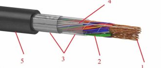
When working with conductors, it is necessary to understand their designation. There are wires and cables that differ from each other in their internal structure and technical characteristics. However, many people often confuse these concepts.
A wire is a conductor that has in its design one wire or a group of wires woven together and a thin common insulating layer.
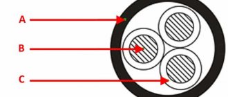
A cable is a core or a group of cores that has both its own insulation and a common insulating layer (sheath).
Each type of conductor will have its own methods for determining cross sections, which are almost similar.
Conductor materials
The amount of energy that a conductor transmits depends on a number of factors, the main one of which is the material of the current-carrying conductors.
- The following non-ferrous metals can be used as the core material of wires and cables:
- Aluminum. Cheap and lightweight conductors, which is their advantage. They are characterized by such negative qualities as low electrical conductivity, a tendency to mechanical damage, high transient electrical resistance of oxidized surfaces;
- Copper. The most popular conductors, which have a high cost compared to other options. However, they are characterized by low electrical and transition resistance at the contacts, fairly high elasticity and strength, and ease of soldering and welding;
- Aluminum copper. Cable products with aluminum cores coated with copper. They are characterized by slightly lower electrical conductivity than their copper counterparts. They are also characterized by lightness, average resistance and relative cheapness.
Cable Diameter Guide
The outer diameter of the cable depends on the number and cross-section of the cores, on the presence, material and quantity of insulating, armoring and protective sheaths. Knowing the diameter is necessary to select cable-supporting structures, to determine containers and vehicles for transporting cable products.
The tables below indicate the nominal outer diameter of cables of different brands with different numbers and cross-sections of cores.
Outer diameter of cables with plastic insulation of brands VVG, AVVG, VBBShV and AVBBShV
| Number of cores and cross-section (mm²) | External diameter (mm) | |
| VVG, AVVG | VBBbShv, AVBbShv | |
| 3 x 35 | 23 | 27,6 |
| 3 x 50 | 27,1 | 31,3 |
| 3 x 70 | 28,7 | 32,9 |
| 3 x 95 | 32,1 | 36,8 |
| 3 x 120 | 36 | 40,2 |
| 3 x 150 | 39,2 | 43,5 |
| 3 x 185 | 42,7 | 47,3 |
| 3 x 240 | 48,9 | 53,2 |
| 3 x 35 + 1 x 16 | 28,4 | 28,2 |
| 3 x 50 + 1 x 25 | 29,2 | 30,8 |
| 3 x 95 + 1 x 50 | 37,4 | 39,2 |
| 3 x 120 + 1 x 70 | 38,9 | 44,1 |
| 3 x 150 + 1 x 70 | 44,6 | 47,6 |
| 3 x 185 + 1 x 50 | — | 53,6 |
| 3 x 185 + 1 x 70 | 50,2 | — |
| 4x 35 | 28,1 | 32,6 |
| 4x 50 | 32,4 | 35,6 |
| 4x 70 | 33,2 | 39 |
| 4x 95 | 37,1 | 43,3 |
| 4 x 120 | 41,2 | 47,4 |
| 4 x 150 | 43,9 | 50,2 |
| 4 x 185 | 49,4 | 54,4 |
Outer diameter of cables ASB, ASBl, ASB2L
| Number and cross-section of cores (mm2) | External diameter (mm) |
| 3x25 cooler | 39,5 |
| 3x35 cooler | 38,3 |
| 3x50 cool | 40,2 |
| 3x70 cooler | 42,9 |
| 3x70 | 44,4 |
| 3x95 cooler | 45,9 |
| 3x95 | 47,5 |
| 3x120 coolant | 48,3 |
| 3x120 | 50,3 |
| 3x150 coolant | 50,7 |
| 3x150 | 52,9 |
| 3x185 coolant | 53,6 |
| 3x185 | 56,3 |
| 3x240 coolant | 57,8 |
| 3x240 | 62 |
NYM cable outer diameter
| Number and cross-section of cores (mm2) | External diameter (mm) |
| 2×1,5 | 8,5 |
| 2×2,5 | 9,7 |
| 2×4 | 11,5 |
| 3×1,5 | 9,0 |
| 3×2,5 | 10,2 |
| 3×4 | 12,0 |
| 4×1,5 | 9,6 |
| 4×2,5 | 11,2 |
| 4×4 | 13,5 |
| 5×1,5 | 10,3 |
| 5×2,5 | 12,0 |
Outer diameter of cable KG
| Section | Diameter (mm) |
| 1x16 | 12,3 |
| 1x25 | 15,3 |
| 1x35 | 16,5 |
| 1x50 | 19,0 |
| 1x70 | 21,8 |
| 2x1.5 | 11,2 |
| 2x2.5 | 12,7 |
| 3x1.5 | 11,8 |
| 3x2.5 | 13,4 |
| 3x1.5+1.5 | 12,7 |
| 3x2.5+1.5 | 15,5 |
| 3x4+2.5 | 16,8 |
| 3x6+4 | 18,5 |
| 3x10+6 | 22,7 |
| 3x16+6 | 24,5 |
| 3x25+10 | 29,9 |
| 3x35+10 | 34,7 |
| 3x50+16 | 41,3 |
| 3x70+25 | 45,2 |
| 3х95+35 | 51,0 |
Outer diameter of cables PVS, ShVVP
| Number and cross-section of cores (mm2) | PVS | SHVVP |
| Diameter (mm) | Diameter (mm) | |
| 2x0.5 | — | 3.1x5.1 |
| 2x0.75 | 6,2 | 3.3x5.4 |
| 2x1.5 | 7,8 | — |
| 2x2.5 | 9,1 | — |
| 3x0.75 | 6,6 | — |
| 3x1.5 | 8,4 | — |
| 3x2.5 | 9,6 | — |
| 4x1.5 | 9,1 | — |
Outer diameter of cables APV, PV-1, PV-3
| Quantity and core cross-section (mm2) | Automatic reclosing | PV-1 | PV-3 |
| Diameter (mm) | Diameter (mm) | Diameter (mm) | |
| 1,5 | — | 3 | 3,4 |
| 2,5 | 3,4 | 3,4 | 4,2 |
| 4 | 3,9 | 3,9 | 4,8 |
| 6 | 4,4 | 4,4 | 6,3 |
| 10 | 5,6 | 5,6 | 7,8 |
| 16 | 7,1 | 7,1 | 8,8 |
| 25 | 8,8 | 8,8 | 11 |
| 35 | 10 | 10 | 12,5 |
| 50 | 11,7 | 11,7 | 14,5 |
| 70 | 13,5 | 13,5 | 15,4 |
| 95 | 15,8 | 15,8 | 18,2 |
| 120 | 17 | — | — |
The tables provide reference information, which may differ from actual information.
intell-electro.ru
How and with what to measure the diameter of a wire (wire)
To measure the diameter of the wire, a caliper or micrometer of any type (mechanical or electronic) is suitable. It’s easier to work with electronic ones, but not everyone has them. You need to measure the core itself without insulation, so first move it aside or remove a small piece. This can be done if the seller allows it. If not, buy a small piece to test and take measurements on it.
On a conductor stripped of insulation, measure the diameter, after which you can determine the actual cross-section of the wire from the found dimensions. Which measuring device is better in this case? If we talk about mechanical models, then a micrometer. Its measurement accuracy is higher. If we talk about electronic options, then for our purposes they both give quite reliable results.
If you don't have a caliper or micrometer, take a screwdriver and a ruler with you. You'll have to strip a fairly decent piece of conductor, so you'll hardly be able to do without buying a test sample this time. So, remove the insulation from a 5-10 cm piece of wire.
Wind the wire around the cylindrical part of the screwdriver. Lay the coils close to each other, without a gap. All turns must be complete, that is, the “tails” of the wire must stick out in one direction - up or down, for example.
The number of turns is not important - about 10. You can have more or less, it’s just easier to divide by 10. Count the turns, then apply the resulting winding to the ruler, aligning the beginning of the first turn with the zero mark (as in the photo). Measure the length of the section occupied by the wire, then divide it by the number of turns. You get the diameter of the wire. It's that simple.
For example, let's calculate the size of the wire shown in the photo above. The number of turns in this case is 11, they occupy 7.5 mm. Divide 7.5 by 11, we get 0.68 mm. This will be the diameter of this wire. Next, you can look for the cross section of this conductor.
Methods for measuring conductor diameter
When selecting an electrical cable or wire to check the cross-section of the core, it is necessary to measure its diameter. There are several ways to do this. You can use measuring instruments such as calipers or micrometers. They measure the size of the exposed part of the conductor.
The device is simply attached to the core, clamped between the jaws, and the result is displayed on the scale. For private use, the measurements are quite accurate, with a small error. Especially if the devices are electronic.
For the second method, you only need a ruler and some kind of even rod. But in this case, you still have to do calculations, albeit very simple ones. More on this method later.
Ruler+rod
If there are no measuring instruments on the farm, you can get by with a regular ruler and any rod of the same diameter. This method has a high error, but if you try it will be quite accurate. Take a piece of wire about 10-20 cm long and remove the insulation.
We wind the bare copper or aluminum wire onto a rod of the same diameter (any screwdriver, pencil, pen, etc. will do). We lay the coils carefully, close to one another. The number of turns is 5-10-15. We count the number of full turns, take a ruler and measure the distance that the wound wire occupies on the rod. Then divide this distance by the number of turns. As a result, we obtain the diameter of the conductor.
For example, we wound 10 turns (it’s easier to count), they took up 3.8 cm (or 38 mm) on the rod. Next, we divide the distance by the number of turns, 38/10 = 3.8 mm, we get that the diameter of the wound wire is 3.8 mm.
As you can see, there is an error here. Firstly, you can lay the wire loosely. Secondly, it is not enough to take accurate measurements. But if you do everything carefully, the discrepancies with the actual sizes will not be so large.
Application of measuring instruments
To determine the diameter of the cores of wires and cables, various measuring instruments are widely used, showing the most accurate results. Basically, the use of micrometers and calipers is practiced for these purposes. Despite their high efficiency, a significant drawback of these devices is their high cost, which is of great importance if the tool is planned to be used only 1-2 times.
As a rule, professional electricians who are constantly engaged in electrical installation work use special devices. With the right approach, it becomes possible to measure the diameter of wire cores even on working lines.
External diameters and weight of cables
Power cables with paper insulation are manufactured in accordance with the requirements of GOST 18410-73 and GOST 18409-73, with plastic insulation - in accordance with the requirements of GOST 16442-80. The structural elements included in the cable, in accordance with the specified GOSTs, have certain limited tolerances from the nominal geometric dimensions. In this regard, the external diameters of the cables and their mass may vary within insignificant limits from the calculated ones. When designing and drawing up work projects in installation organizations, it is necessary to use the calculated outer diameters for each cable brand, depending on its design and core cross-section. For transportation and loading and unloading operations, it is necessary to take into account not only the weight of the cable, but also the weight of the cable drum. In table The calculated outer diameter and weight of cables with paper insulation for voltages of 1 and 10 kV and cables with plastic insulation for voltages of 1 kV are indicated.
External diameter, weight of three-core cables with copper conductors in a lead sheath of the SGU, SBGU, SBU and SBLU brands for a voltage of 1 kV according to GOST 18410-73
| Number of cable cores x cross-section, mm2 | External diameter, mm | Estimated weight, kg/km | ||||||
| SSU | SBSU | SBU | SBLU | SSU | SBSU | SBU | SBLU | |
| 3 x 35 | 20,2 | 25,3 | 29,7 | 30,7 | 2212 | 2440 | 2699 | 2780 |
| 3 x 35* | 19,3 | 24,4 | 28,8 | 29,8 | 2127 | 2349 | 2599 | 2679 |
| 3 x 50 | 22,8 | 27,9 | 32,3 | 33,3 | 2806 | 3050 | 3334 | 3420 |
| 3 x 50* | 20.3 | 25.7 | 30.1 | 31.1 | 2376 | 2727 | 2953 | 3033 |
| 3 x 70 | 24,8 | 30,1 | 34,5 | 35,5 | 3360 | 3711 | 3971 | 4211 |
| 3 x 95 | 28,1 | 33,3 | 37,7 | 38,7 | 4350 | 4711 | 4996 | 5094 |
| 3 x 120 | 31,7 | 36,8 | 41,2 | 42,2 | 5462 | 5788 | 6100 | 6206 |
| 3 x 150 | 36,9 | 41,8 | 46,2 | 47,2 | 7166 | 7366 | 7774 | 7895 |
| 3 x 185 | 41 | 45,6 | 50 | 57 | 8863 | 8814 | 9286 | 9412 |
| 3 x 240 | 45,8 | 50,6 | 55 | 58 | 10076 | 11499 | 11499 | 11641 |
* Solid wires
External diameter, weight of four-core cables with copper conductors in a lead sheath of the SGU, SBGU, SBU and SBLU brands for a voltage of 1 kV according to GOST 18410-73
| Number of cores x section, mm2 | External diameter, mm | Estimated weight, kg/ | km | |||||
| SSU | SBSU | SBU | SBLU | SSU | SBSU | SBU | SBLU | |
| 3 x 35 + 1 x 16 | 22,1 | 27,2 | 31,6 | 32,6 | 2520 | 2761 | 3037 | 3123 |
| 3 x 35 + 1 x 16* | 20,7 | 25,8 | 30,2 | 31,2 | 2395 | 2627 | 2889 | 2973 |
| 3 x 50 + 1 x 25 | 24,6 | 29,7 | 34,1 | 35,1 | 3218 | 3505 | 3804 | 3899 |
| 3 x 50 + 1 x 25* | 22.8 | 27.9 | 32,3 | 33.3 | 3006 | 3255 | 3538 | 3625 |
| 3 x 70 + 1 x 25 | 28,6 | 33,8 | 38,2 | 39,2 | 4211 | 4545 | 4883 | 4985 |
| 3 x 95 + 1 x 35 | 30 | 35,2 | 39,6 | 42,4 | 4886 | 5244 | 5544 | 5647 |
| 3 x 120 + 1 x 35 | 33,4 | 38,5 | 42,9 | 46,6 | 5924 | 6262 | 6587 | 6698 |
| 3 x 120 + 1 x 70 | 35,4 | 42,5 | 44,9 | 47,9 | 6196 | 7016 | 7192 | 7291 |
| 3 x 150 + 1 x 50 | 36,6 | 43,6 | 46 | 50,1 | 7209 | 7501 | 7850 | 7969 |
| 3 x 185 + 1 x 50 | 43,9 | 48,5 | 52 | 53,9 | 9649 | 9721 | 10090 | 10225 |
External diameter, weight of four-core power cables with copper conductors in a lead sheath of the SGU, SBGU, SBU and SBLU brands for a voltage of 1 kV according to GOST 18410-73
| Number of cores x cross-section, mm2 | External diameter, mm | Estimated weight, kg/ | km | |||||
| SSU | SBSU | SBU | SBLU | SSU | SBSU | SBU | SBLU | |
| 4 x 35* | 22,1 | 27,2 | 31,6 | 32,6 | 2659 | 2899 | 3174 | 3262 |
| 4x 35 | 24 | 29.1 | 33.5 | 34,5 | 2900 | 3152 | 3447 | 3568 |
| 4 x 50* | 24,9 | 30 | 34,4 | 35,4 | 3474 | 3731 | 4033 | 4126 |
| 4x 50 | 28,6 | 33,8 | 38,2 | 39,2 | 3906 | 4243 | 4578 | 4680 |
| 4x 70 | 30,7 | 35,6 | 40 | 41 | 4937 | 5116 | 5468 | 5580 |
| 4x 95 | 34,2 | 39,1 | 43,5 | 44,5 | 6262 | 6450 | 6834 | 6951 |
| 4 x 120 | 38,7 | 43,6 | 48 | 49 | 7752 | 7954 | 8379 | 8504 |
* Solid wires
External diameter, weight of three-core cables with aluminum conductors in a lead sheath, brands ASGU, ASBGU, ASBU, ASKLU for voltage 10 kV according to GOST 18410-73
| Number of cores X x section, mm2 | External diameter, mm | Estimated weight, kg/km | ||||||
| ASSU | ASBSU | ASBU | ASCLU | ASSU | ASBSU | ASBU | ASCLU | |
| 3 x 35* | 28,8 | 34 | 38,4 | 47,2 | 2578 | 2926 | 3216 | 6256 |
| 3 x 50* | 30,7 | 35,9 | 40,3 | 49,1 | 2851 | 3216 | 3521 | 6667 |
| 3 x 70* | 33,6 | 38,7 | 43,1 | 52 | 3349 | 3688 | 4014 | 7524 |
| 3 x 95* | 36,6 | 41,8 | 46,2 | 55,2 | 4044 | 4337 | 4680 | 8486 |
| 3 x 120* | 39,4 | 44,4 | 48,8 | 57,8 | 4596 | 4868 | 5259 | 9291 |
| 3 x 150 | 44,6 | 49,2 | 53,6 | 63 | 5929 | 5900 | 6373 | 11209 |
| 3 x 150* | 41,8 | 46,7 | 51,1 | 60,2 | 5161 | 5402 | 5791 | 10104 |
| 3 x 185 | 47,9 | 52,5 | 56,9 | 66,3 | 6773 | 7673 | 7239 | 12373 |
| 3 x 185* | 44,8 | 49,7 | 54,1 | 63,2 | 5882 | 6117 | 6529 | 11087 |
| 3 x 240 | 52,8 | 58,6 | 63 | 75,2 | 8022 | 8591 | 9151 | 16768 |
| 3 x 240* | 49 | 55,8 | 58,1 | 67,4 | 6942 | 7356 | 7562 | 12534 |
* Solid wires
External diameter, weight of three-core cables with aluminum cores in an aluminum sheath of brands AAShvU, AAShpsU, AABlGU, AABlU, AAB2luU for voltage 10 kV according to GOST 18410-73
| Number of cores | External diameter, mm | Estimated weight, kg/km | ||||||
| x section, mm2 | AAShvU AAShpsU | AABLGU | ААБЛУ ААБ2лУ | AASHvU | AAShpsU | AABLGU | AABlU | AAB2luU |
| 3 x 35* | 33,8 | 36 | 40,4 | 1518 | 1441 | 2096 | 2429 | 2464 |
| 3 x 50* | 36,5 | 38,3 | 42,7 | 1792 | 1699 | 2377 | 2729 | 2766 |
| 3 x 70* | 38,8 | 40,6 | 45 | 2077 | 1979 | 2698 | 3070 | 3110 |
| 3 x 70 | 40,8 | 42,6 | 47 | 2221 | 2117 | 2873 | 3262 | 3304 |
| 3 x 95* | 41,7 | 43,3 | 47,9 | 2462 | 2356 | 3128 | 3526 | 3567 |
| 3 x 95 | 42,9 | 45,7 | 50,1 | 2642 | 2530 | 3342 | 3758 | 3803 |
| 3 x 120* | 44,1 | 45,9 | 50,3 | 2810 | 2698 | 3513 | 3930 | 3976 |
| 3 x 120 | 48 | 49,4 | 53,8 | 3166 | 3031 | 3882 | 4329 | 4378 |
| 3 x 150* | 47,4 | 48,8 | 53,2 | 3308 | 3176 | 4016 | 4458 | 4506 |
| 3 x 150 | 50,9 | 52,3 | 56,7 | 3631 | 3188 | 4390 | 4862 | 4916 |
| 3 x 185* | 50,4 | 51,8 | 56,2 | 3805 | 3664 | 4557 | 5026 | 5976 |
| 3 x 185 | 53,9 | 55,8 | 59,7 | 4114 | 3963 | 4917 | 5415 | 5470 |
| 3 x 240* | 54,2 | 55,6 | 60 | 4473 | 4321 | 5280 | 5780 | 5836 |
| 3 x 240 | 59,3 | 61,5 | 65,9 | 4988 | 4807 | 6467 | 7048 | 7079 |
External diameter, weight of three-core cables with paper insulation impregnated with a non-drip compound, brands TsSBU, TsASBU, TsAASHvU, TsAABLU for voltage 1 kV according to GOST 18409-73
| Number of cores x cross-section, mm2 | External diameter, mm | Estimated weight, kg/: | km | |||||
| CSBU | TsASBU | CAASHvU | TsAABLU | CSBU | TsASBU | CAASHvU | TsAABLU | |
| 3 x 35* | 41,8 | 42 | 37,3 | 43,3 | 4564 | 3830 | 1755 | 2792 |
| 3 x 35 | 44,4 | — | — | — | 4954 | — | — | — |
| 3 x 50* | 45,3 | 45,5 | 39,6 | 46,6 | 5448 | 4431 | 2010 | 3173 |
| 3 x 50 | 47 | — | — | — | 5692 | — | — | — |
| 3 x 70* | — | 47,8 | 41,9 | 48,6 | — | 5001 | 2332 | 3552 |
| 3 x 70 | 52,9 | 49,9 | 44 | 51 | 6731 | 5291 | 2471 | 3745 |
| 3 x 95* | — | 50,5 | 44,9 | 51,9 | — | 5547 | 2753 | 4051 |
| 3 x 95 | 52,9 | 52,9 | 47,7 | 54,3 | 7808 | 5890 | 2973 | 4292 |
| 3 x 120* | — | 52,9 | 47,7 | 54,3 | — | 6066 | 3149 | 4469 |
| 3 x 120 | 56,4 | 56,4 | 51,2 | 57,8 | 9108 | 6710 | 3441 | 4846 |
| 3 x 150* | — | 55,8 | 50,6 | 57,2 | — | 6849 | 3621 | 5014 |
| 3 x 150 | 59,2 | 59,2 | 54 | 60,6 | 11521 | 7350 | 3406 | 5361 |
| 3 x 185* | — | 58,3 | 53,1 | 59,7 | — | 7471 | 4070 | 5523 |
| 3 x 185 | 63,5 | 63,5 | 67,5 | 64,9 | 12547 | 8899 | 4481 | 5658 |
* Solid wires
External diameter, weight of cables with plastic insulation of brands VVG, AVVG, VBbShv and AVBbShv for voltage 1 kV according to GOST 16442-80
| Number of cores x cross-section, mm2 | External diameter, mm | Estimated weight, kg/km | ||||
| VVG, AVVG | VBBbShv, AVBbShv | VVG | A B C D | VBBShv | AVBbShv | |
| 3 x 35 | 23 | 27,6 | 1221 | 562 | 1688 | 1024 |
| 3 x 50 | 27,1 | 31,3 | 1720 | 780 | 2233 | 1294 |
| 3 x 70 | 28,7 | 32,9 | 2379 | 1054 | 2909 | 1584 |
| 3 x 95 | 32,1 | 36,8 | 3146 | 1348 | 3771 | 1973 |
| 3 x 120 | 36 | 40,2 | 3923 | 1545 | 4585 | 2314 |
| 3 x 150 | 39,2 | 43,5 | 4832 | 1867 | 5553 | 2715 |
| 3 x 185 | 42,7 | 47,3 | 5885 | 2384 | 6712 | 3211 |
| 3 x 240 | 48,9 | 53,2 | 7604 | 3062 | 8501 | 3959 |
| 3 x 35 + 1 x 16 | 28,4 | 28,2 | 1429 | 668 | 1919 | 1159 |
| 3 x 50 + 1 x 25 | 29,2 | 30,8 | 2005 | 907 | 2570 | 1472 |
| 3 x 70 + 1 x 35 | 33,2 | 35,6 | 2660 | 1176 | 3248 | 1764 |
| Number of cores x cross-section, mm2 | External diameter, mm | Estimated weight, kg/km | ||||
| VVG, AVVG | VBBbShv, AVBbShv | VVG | A B C D | VBBShv | AVBbShv | |
| 3 x 95 + 1 x 50 | 37,4 | 39,2 | 3551 | 1534 | 4214 | 2196 |
| 3 x 120 + 1 x 70 | 38,9 | 44,1 | 4299 | 1809 | 5025 | 2535 |
| 3 x 150 + 1 x 70 | 44,6 | 47,6 | 5364 | 2112 | 6205 | 3058 |
| 3 x 185 + 1 x 50 | — | 53,6 | — | — | 7324 | 3509 |
| 3 x 185 + 1 x 70 | 50,2 | — | 5457 | 2642 | — | — |
| 4x 35 | 28,1 | 32,6 | 1615 | 737 | 2110 | 1231 |
| 4x 50 | 32,4 | 35,6 | 2247 | 995 | 2817 | 1564 |
| 4x 70 | 33,2 | 39 | 3106 | 1340 | 3661 | 1895 |
| 4x 95 | 37,1 | 43,3 | 4118 | 1721 | 4771 | 2374 |
| 4 x 120 | 41,2 | 47,4 | 5139 | 2112 | 5832 | 2804 |
| 4 x 150 | 43,9 | 50,2 | 6341 | 2556 | 7094 | 3309 |
| 4 x 185 | 49,4 | 54,4 | 7773 | 3105 | 8596 | 3928 |
External diameter, weight of cables with plastic insulation grades APsVG and APsBBShV for voltage 1 kV according to GOST 16442-80
| Number of cores x cross-section, mm2 | External diameter, mm | Estimated weight, kg/km | ||
| APsVG | APsBBShv | APsVG | APsBBShv | |
| 3 x 35 + 1 x 16 | 28,4 | 28,2 | 632 | 1122 |
| 3 x 50 + 1 x 25 | 29,2 | 30,8 | 856 | 1421 |
| 3 x 70 + 1 x 35 | 33,2 | 35,6 | 1102 | 1620 |
| 3 x 95 + 1 x 50 | 37,4 | 39,2 | 1443 | 2106 |
| 3 x 120 + 1 x 70 | 38,9 | 44,1 | 1708 | 2434 |
| 3 x 150 + 1 x 70 | 44,6 | 47,6 | 2090 | 2931 |
| 3 x 185 + 1 x 50 | 50,6 | 53,6 | 2503 | 3369 |
Outer diameters, mm, of three-core 660V cables with rubber insulation for fixed installation
| Core cross-section, mm | JWG | SRB | VRG, NRG | Core cross-section, mm | JWG | SRB | VRG, NRG | Core cross-section, mm | JWG | SRB | VRG, NRG |
| 1 | 9 | 17 | 11 | 10 | 18 | 26 | 20 | 70 | 34 | 45 | 39. |
| 1,5 | 10 | 18 | 12 | 16 | 20 | 28 | 22 | 95 | 40 | 50 | 44 |
| 2,5 | 11 | 18 | 13 | 25 | 24 | 34 | 27 | 120 | 43 | 54 | 47 |
| 4 | 12 | 19 | 14 | 35 | 26 | 37 | 29 | 150 | 47 | 58 | 52 |
| 6 | 13 | 20 | 15 | 50 | 31 | 41 | 34 | 185 | 52 | 63 | 57 |
About choosing a cable brand for home wiring
Making apartment electrical wiring from aluminum wires at first glance seems cheaper, but operating costs due to low reliability of contacts over time will be many times higher than the costs of electrical wiring made from copper.
It is recommended to make wiring exclusively from copper wires! Aluminum wires are indispensable when laying overhead electrical wiring, as they are light and cheap and, when properly connected, serve reliably for a long time.
Which wire is better to use when installing electrical wiring, single-core or stranded? From the point of view of the ability to conduct current per unit of cross-section and installation, single-core is better. So for home wiring you only need to use solid wire.
Stranded allows multiple bends, and the thinner the conductors in it, the more flexible and durable it is. Therefore, stranded wire is used to connect non-stationary electrical appliances to the electrical network, such as an electric hair dryer, an electric razor, an electric iron and all the others.
After deciding on the cross-section of the wire, the question arises about the brand of cable for electrical wiring. The choice here is not great and is represented by only a few brands of cables: PUNP, VVGng and NYM.
PUNP cable since 1990, in accordance with the decision of Glavgosenergonadzor “On the ban on the use of wires such as APVN, PPBN, PEN, PUNP, etc., produced according to TU 16-505. 610-74 instead of APV, APPV, PV and PPV wires according to GOST 6323-79*" is prohibited for use.
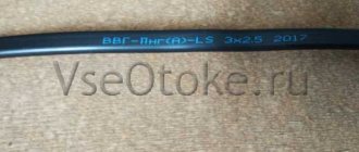
Cable VVG and VVGng - copper wires in double polyvinyl chloride insulation, flat shape. Designed for operation at ambient temperatures from −50°С to +50°С, for wiring inside buildings, outdoors, in the ground when laid in tubes. Service life up to 30 years.
The letters “ng” in the brand designation indicate the non-flammability of the wire insulation. Two-, three- and four-core wires are available with core cross-sections from 1.5 to 35.0 mm2. If in the cable designation there is a letter A (AVVG) before VVG, then the conductors in the wire are aluminum.
The NYM cable (its Russian analogue is the VVG cable) with round copper cores with non-flammable insulation, complies with the German standard VDE 0250. Technical characteristics and scope of application are almost the same as the VVG cable. Two-, three- and four-core wires are available with core cross-sections from 1.5 to 4.0 mm2.
As you can see, the choice for laying electrical wiring is not large and is determined depending on what shape the cable is more suitable for installation, round or flat. A round-shaped cable is more convenient to lay through walls, especially if the connection is made from the street into the room. You will need to drill a hole slightly larger than the diameter of the cable, and with a larger wall thickness this becomes relevant. For internal wiring, it is more convenient to use a VVG flat cable.
Conditions for installation and operation of the VVG power cable
Operation of VVG cable at ambient temperatures from -50°С to +50°С. Recommended for installation outdoors, in dry and damp industrial areas. The VVG cable, which has a filling between the cores, made in accordance with GOST, can be laid in the ground under conditions of low corrosive activity of the soil and the absence of significant mechanical loads. Can be laid without preheating at a temperature not lower than minus 15°C. The minimum bending radius during installation must be at least 7.5 times the outer diameter of the cable. Does not propagate combustion when laid alone. The service life of the VVG cable is 30 years.
Dependence of current, power and core cross-section
It is not enough to measure and calculate the cross-sectional area of the cable based on the diameter of the core. Before installing wiring or other types of electrical networks, it is also necessary to know the capacity of the cable products.
- When choosing a cable, you must be guided by several criteria:
- the strength of the electric current that the cable will pass;
- consumer power;
- current load exerted on the cable.
Power
The most important parameter during electrical installation work (in particular, cable laying) is throughput. The maximum power of electricity transmitted through it depends on the cross-section of the conductor. Therefore, it is extremely important to know the total power of the energy consumption sources that will be connected to the wire.
Typically, manufacturers of household appliances, appliances and other electrical products indicate on the label and in the documentation accompanying them the maximum and average power consumption.
For example, a washing machine can consume electricity ranging from tens of W/h during rinsing mode to 2.7 kW/h when heating water.
Accordingly, a wire with a cross-section that is sufficient to transmit electricity of maximum power must be connected to it. If two or more consumers are connected to the cable, then the total power is determined by adding the limit values of each of them.
The average power of all electrical appliances and lighting devices in an apartment rarely exceeds 7500 W for a single-phase network. Accordingly, the cable cross-sections in the electrical wiring must be selected to this value.
It is recommended to round the cross-section towards higher power due to a possible increase in power consumption in the future. Typically, the next largest cross-sectional area from the calculated value is taken. So, for a total power of 7.5 kW, it is necessary to use a copper cable with a core cross-section of 4 mm2, which is capable of transmitting about 8.3 kW. The cross-section of the conductor with an aluminum core in this case must be at least 6 mm2, passing a current power of 7.9 kW.
In individual residential buildings, a three-phase power supply system of 380 V is often used. However, most equipment is not designed for such electrical voltage. A voltage of 220 V is created by connecting them to the network through a neutral cable with an even distribution of the current load across all phases.
Electric current
Often the power of electrical equipment and equipment may not be known to the owner due to the absence of this characteristic in the documentation or completely lost documents and labels. There is only one way out in such a situation - to calculate using the formula yourself.
Power is determined by the formula:
P = U*I
- Where:
- P – power, measured in watts (W);
- I – electric current strength, measured in amperes (A);
- U is the applied electrical voltage, measured in volts (V).
- When the strength of the electric current is unknown, it can be measured using instrumentation:
- ammeter;
- multimeter;
- current clamps.
After determining the power consumption and electric current, you can use the table below to find out the required cable cross-section.
Load
Calculation of the cross-section of cable products based on current load must be carried out to further protect them from overheating. When too much electric current passes through conductors for their cross-section, destruction and melting of the insulating layer can occur.
The maximum permissible long-term current load is the quantitative value of the electric current that can pass the cable for a long time without overheating. To determine this indicator, it is initially necessary to sum up the powers of all energy consumers.
After this, calculate the current load using the formulas:
single-phase network: I = P∑*Ki/U
three-phase network: I = P∑*Ki/(√3*U)
- Where:
- P∑ – total power of energy consumers;
- Ki – coefficient equal to 0.75;
- U – electrical voltage in the network.
Main technical characteristics of cable VVG 5x4
We presented all the cable characteristics necessary for ordering and calculation in the form of a table.
| Characteristic name | Unit change | Meaning |
| GOST | — | GOST 31996-2012 |
| Core class according to GOST 22483-2012 | — | 1 |
| OKP code | — | 35 2122; 35 3371 |
| Fire hazard class | — | O1.8.2.5.4 |
| Operating temperature range | °C | -50 to 50 |
| Minimum installation temperature | °C | -15 |
| Duration of operation | years | 30 |
| Mains voltage | IN | up to 1000 |
| AC frequency in the network | Hz | 50 Hz |
| Allowable tensile force | N | 600 |
| Maximum permissible core heating temperature during short circuit | °C | 160 |
| Short circuit duration, no more | With | 5 |
| Estimated mass (weight) of the cable, 0.66 kV | kg/km | 349 |
| Estimated mass (weight) of one meter of cable, 0.66 kV | kg/m | 349/1000 |
| Estimated mass (weight) of cable, 1 kV | kg/km | 400 |
| Estimated mass (weight) of one meter of cable, 1 kV | kg/m | 400/1000 |
| Allowable bending radius | mm | 152 |
| Permissible current load when laying in air | A | 36 |
| Permissible current load when laying in the ground | A | 47 |
| Permissible one-second short circuit current | A | 0.43 |
| Volume of combustible mass | l/km | 202 |
| Core insulation resistance | MOhm/km | 10 |
| Core insulation thickness, 1 kV | mm | 1 |
| Core insulation thickness, 0.66 kV | mm | 0.7 |
| Mass of non-ferrous metal | g/m | 178 |
| Maximum power when installed in air, 220 V | kW | 10.56 |
| Maximum power when installed in the ground, 220 V | kW | 13.79 |
| Maximum power when installed in air, 380 V | kW | 23.69 |
| Maximum power when installed in the ground, 380 V | kW | 30.93 |
| Core heating temperature based on non-ignition conditions | °C | 350 |
| Long-term permissible core heating temperature | °C | 70 |
| Permissible temperature in overload mode | °C | 90 |
| Electrical resistance of the conductor | Ohm/km | 4.61 |
Expert opinion
Chief Editor of LinijaOpory
Alexander Novikov is the main author and inspirer of our site. Author of diagrams and drawings.
Before making calculations, we recommend that you additionally request cable characteristics from the manufacturer!
Stranded wire
The PVS cable for connecting power tools and electrical appliances is made flexible, since all the cores are stranded. Measuring the diameter of the harness at the same time will give an incorrect result, since there are air gaps inside. The correct calculation principle is the same as for cable.
The core should be fluffed up, count how many wires are in it, and then measure the diameter of one of them. Knowing their total number in the vein, you can calculate the total cross-section using the previous formula. It’s best to take measurements using a micrometer. It is more convenient to use, since the caliper easily presses through thin wires.
How to calculate the cross-section of a stranded wire
Stranded wire, or as it is also called stranded or flexible, is a single-core wire twisted together. To calculate the cross-section of a stranded wire, you must first calculate the cross-section of one wire, and then multiply the resulting result by their number.
Let's look at an example. There is a multi-core flexible wire, in which there are 15 cores with a diameter of 0.5 mm. The cross-section of one core is 0.5 mm × 0.5 mm × 0.785 = 0.19625 mm2, after rounding we get 0.2 mm2. Since we have 15 wires in the wire, to determine the cable cross-section we need to multiply these numbers. 0.2 mm2×15=3 mm2. It remains to determine from the table that such a stranded wire will withstand a current of 20 A.
You can estimate the load capacity of a stranded wire without measuring the diameter of an individual conductor by measuring the total diameter of all twisted wires. But since the wires are round, there are air gaps between them. To eliminate the gap area, you need to multiply the result of the wire cross-section obtained from the formula by a factor of 0.91. When measuring the diameter, you need to make sure that the stranded wire does not flatten.
Let's look at an example. As a result of measurements, the stranded wire has a diameter of 2.0 mm. Let's calculate its cross-section: 2.0 mm × 2.0 mm × 0.785 × 0.91 = 2.9 mm2. Using the table (see below), we determine that this stranded wire will withstand a current of up to 20 A.
Design features of VVG 5x6
The table below shows the design features of the cable.
| Characteristic name | Unit change | Meaning |
| Number of cores | PC. | 5 |
| Maximum core diameter | mm | 2.9 |
| Cable outer diameter, 0.66 kV | mm | 15 |
| Cable outer diameter, 1 kV | mm | 16.5 |
| Weight Limit | kg/m | 0.516 |
| Core material | — | Copper |
| Insulation material | — | PVC |
| Shell material | — | PVC |
| Core construction type | — | OK |
Core design options:
- ok - single-wire core;
- mk - multi-wire core.
Undersized wire cross-section - what is the danger?
So, let's consider the dangers that await us when using low-quality wires in everyday life. It is clear that the current characteristics of current-carrying conductors decrease in direct proportion to the decrease in their cross-section. The load capacity of the wire decreases due to the reduced cross-section. According to the standards, the current that the wire can pass through is calculated. It will not collapse if less current passes through it.
The resistance between the cores decreases if the insulation layer is thinner than required. Then, in an emergency situation, when the supply voltage increases, a breakdown may occur in the insulation. If, along with this, the core itself has a reduced cross-section, that is, it cannot pass the current that, according to standards, it should pass, the thin insulation begins to gradually melt.
All these factors will inevitably lead to a short circuit and then to a fire. A fire occurs from sparks that appear during a short circuit. Let me give you an example: a three-core copper wire (for example, with a cross-section of 2.5 2), according to regulatory documentation, can pass 27 A for a long time, usually 25 A is considered.
But the wires that come into my hands, produced in accordance with the specifications, actually have a cross-section from 1.8 mm2 to 2 mm2 (this is with the declared 2.5 mm2). Based on the regulatory documentation, a wire with a cross-section of 2 mm2 can carry a current of 19 A for a long time.
Therefore, if a situation occurs when a current designed for such a cross-section flows through the wire you have chosen, which supposedly has a cross-section of 2.5 mm2, the wire will overheat. And with prolonged exposure, the insulation will melt, followed by a short circuit.
Contact connections (for example, in a socket) will collapse very quickly if such overloads occur regularly. Therefore, the socket itself, as well as the plugs of household appliances, may also be subject to melting.
Now imagine the consequences of all this! It’s especially disappointing when a beautiful renovation has been made, new appliances have been installed, for example, an air conditioner, an electric oven, a hob, a washing machine, an electric kettle, a microwave oven. And so you put the buns in the oven to bake, started the washing machine, turned on the kettle, and even the air conditioner, since it became hot.
These switched on devices are enough to cause smoke to come out of junction boxes and sockets. Then you will hear a pop, which is accompanied by a flash. And after that the electricity will disappear. It will still end well if you have circuit breakers.
What if they are of low quality? Then you won't get away with a bang and a flash. A fire will start, accompanied by sparks from the wiring burning in the wall. The wiring will burn in any case, even if it is tightly walled under the tile.
The picture I described makes it clear how responsibly you need to choose wires. After all, you will use them in your home. This is what it means to follow not GOSTs, but TUs.
Calculation of the cross-section of electrical wiring according to the power of connected electrical appliances
To select the cross-section of cable wire cores when laying electrical wiring in an apartment or house, you need to analyze the fleet of existing electrical household appliances from the point of view of their simultaneous use. The table provides a list of popular household electrical appliances indicating the current consumption depending on the power.
You can find out the power consumption of your models yourself from the labels on the products themselves or data sheets; often the parameters are indicated on the packaging. If the current consumed by an electrical appliance is not known, it can be measured using an ammeter.
Table of power consumption and current for household electrical appliances at a supply voltage of 220 V
Typically, the power consumption of electrical appliances is indicated on the housing in watts (W or VA) or kilowatts (kW or kVA). 1 kW=1000 W.
Table of power/current consumption of household electrical appliances
| electrical appliance | Power consumption, W | Current strength, A |
| Washing machine | 2000 – 2500 | 9,0 – 11,4 |
| Jacuzzi | 2000 – 2500 | 9,0 – 11,4 |
| Electric floor heating | 800 – 1400 | 3,6 – 6,4 |
| Stationary electric stove | 4500 – 8500 | 20,5 – 38,6 |
| microwave | 900 – 1300 | 4,1 – 5,9 |
| Dishwasher | 2000 – 2500 | 9,0 – 11,4 |
| Freezers, refrigerators | 140 – 300 | 0,6 – 1,4 |
| Electric meat grinder | 1100 – 1200 | 5,0 – 5,5 |
| Electric kettle | 1850 – 2000 | 8,4 – 9,0 |
| Electric coffee maker | 630 – 1200 | 3,0 – 5,5 |
| Juicer | 240 – 360 | 1,1 – 1,6 |
| Toaster | 640 – 1100 | 2,9 – 5,0 |
| Mixer | 250 – 400 | 1,1 – 1,8 |
| Hairdryer | 400 – 1600 | 1,8 – 7,3 |
| Iron | 900 –1700 | 4,1 – 7,7 |
| Vacuum cleaner | 680 – 1400 | 3,1 – 6,4 |
| Fan | 250 – 400 | 1,0 – 1,8 |
| TV | 125 – 180 | 0,6 – 0,8 |
| Radio equipment | 70 – 100 | 0,3 – 0,5 |
| Lighting devices | 20 – 100 | 0,1 – 0,4 |
Current is also consumed by the refrigerator, lighting fixtures, radiotelephone, chargers, and TV in standby mode. But in total this power is no more than 100 W and can be ignored in calculations.
If you turn on all the electrical appliances in the house at the same time, you will need to select a wire cross-section capable of passing a current of 160 A. You will need a finger-thick wire! But such a case is unlikely. It’s hard to imagine that someone is capable of grinding meat, ironing, vacuuming and drying hair at the same time.
Calculation example. You got up in the morning, turned on the electric kettle, microwave, toaster and coffee maker. The current consumption will accordingly be:
7 A + 8 A + 3 A + 4 A = 22 A
Taking into account the switched on lighting, refrigerator and, in addition, for example, a TV, the current consumption can reach 25 A.
Selecting a wire cross-section for connecting electrical appliances to a three-phase 380 V network
When operating electrical appliances, for example, an electric motor, connected to a three-phase network, the consumed current no longer flows through two wires, but through three and, therefore, the amount of current flowing in each individual wire is somewhat less. This allows you to use a smaller cross-section wire to connect electrical appliances to a three-phase network.
To connect electrical appliances to a three-phase network with a voltage of 380 V, for example an electric motor, the wire cross-section for each phase is taken 1.75 times less than for connecting to a single-phase 220 V network. Attention, when choosing the wire cross-section for connecting an electric motor by power, you should take into account that The motor nameplate indicates the maximum mechanical power that the motor can produce at the shaft, not the electrical power consumed.
The electrical power consumed by the electric motor, taking into account efficiency and cos φ, is approximately two times greater than that created on the shaft, which must be taken into account when choosing the wire cross-section based on the motor power indicated on the plate.
For example, you need to connect an electric motor that consumes power from a 2.0 kW network. The total current consumption of an electric motor of such power in three phases is 5.2 A. According to the table, it turns out that a wire with a cross-section of 1.0 mm2 is needed, taking into account the above 1.0 / 1.75 = 0.5 mm2. Therefore, to connect a 2.0 kW electric motor to a three-phase 380 V network, you will need a three-core copper cable with a cross-section of each core of 0.5 mm2.
It is much easier to choose the wire cross-section for connecting a three-phase motor based on the current consumption, which is always indicated on the nameplate. For example, the current consumption of a 0.25 kW motor for each phase at a supply voltage of 220 V (the motor windings are connected in a delta configuration) is 1.2 A, and at a voltage of 380 V (the motor windings are connected in a star configuration) it is only 0.7 A.
Taking the current strength indicated on the nameplate, according to the table for selecting the wire cross-section for apartment electrical wiring, we select a wire with a cross-section of 0.35 mm2 when connecting the electric motor windings in a “triangle” pattern or 0.15 mm2 when connecting in a “star” pattern.
Table - diameter and weight of VVG cable
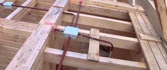
PUE 2.1.61. In boxes (cable tray + cover), wires and cables can be laid in multi-layers with an ordered and random (scattered) mutual arrangement. The sum of the cross-sections of wires and cables, calculated by their outer diameters, including insulation and outer sheaths, should not exceed: for blind boxes (non-perforated tray + cover) 35% of the clear cross-section of the box; for boxes with openable lids 40%.
It is advisable to use these conditions as a guide when calculating and selecting the size of cable pipes, metal trays, plastic boxes or to calculate the cost of delivery of cable products.
External diameter and weight of VVG cable
- single-core
- two-wire
- three-core
- four-wire
- five-core
| Number and nominal cross-section of cores, mm2 | Cable outer diameter, mm | Weight of 1 km cable, kg | ||
| 0.66 kV | 1 kV | 0.66 kV | 1 kV | |
| VVG brand cables with round cores | ||||
| 1×1,5 | 5,0 | 5,4 | 39 | 44 |
| 1×2,5 | 5,4 | 5,8 | 50 | 55 |
| 1×4 | 6,0 | 6,6 | 70 | 78 |
| 1×6 | 6,5 | 7,1 | 91 | 99 |
| 1×10 | 7,8 | 8,0 | 140 | 143 |
| 1×16 | 9,9 | 10,1 | 224 | 229 |
| 1×25 | 11,0 | 11,2 | 321 | 327 |
| 1×35 | 12,0 | 12,2 | 418 | 423 |
| 1×50 | 13,5 | 13,7 | 550 | 556 |
| 1×70 | 15,2 | 765 | ||
| 1×95 | 17,3 | 1028 | ||
| 1×120 | 19,2 | 1279 | ||
| 1×150 | 22,2 | 1595 | ||
| 1×185 | 24,7 | 1993 | ||
| 1×240 | 27,7 | 2573 | ||
| 2×1,5 | 7,6 | 8,4 | 72 | 81 |
| 2×2,5 | 8,3 | 9,7 | 94 | 117 |
| 2×4 | 10,3 | 11,5 | 147 | 165 |
| Number and nominal cross-section of cores, mm2 | Cable outer diameter, mm | Weight of 1 km cable, kg | ||
| 0.66 kV | 1 kV | 0.66 kV | 1 kV | |
| 2×6 | 11,3 | 12,5 | 191 | 210 |
| 2×10 | 13,7 | 14,1 | 293 | 300 |
| 2×16 | 16,7 | 16,7 | 442 | 449 |
| 2×25 | 19,4 | 19,8 | 657 | 667 |
| 2×35 | 21,4 | 21,8 | 854 | 865 |
| 2×50 | 24,8 | 25,2 | 1146 | 1160 |
| 2×70 | 28,2 | 1587 | ||
| 2×95 | 32,4 | 2127 | ||
| 2×120 | 35,8 | 2638 | ||
| 2×150 | 41,8 | 3288 | ||
| 3×1,5 | 8,0 | 9,5 | 93 | 117 |
| 3×2,5 | 9,4 | 10,3 | 137 | 151 |
| 3×4 | 10,8 | 12,1 | 194 | 218 |
| 3×6 | 11,9 | 13,2 | 257 | 282 |
| 3×10 | 14,5 | 14,9 | 403 | 413 |
| 3×16 | 17,8 | 17,8 | 619 | 928 |
| 3×25 | 20,6 | 21,0 | 926 | 941 |
| 3×35 | 22,7 | 23,2 | 1203 | 1232 |
| 3×50 | 26,4 | 26,8 | 1635 | 1653 |
| 3×4+1×2,5 | 11,8 | 12,8 | 229 | 253 |
| 3×6+1×4 | 13,0 | 14,4 | 308 | 339 |
| 3×10+1×6 | 15,4 | 16,4 | 471 | 490 |
| Number and nominal cross-section of cores, mm2 | Cable outer diameter, mm | Weight of 1 km cable, kg | ||
| 0.66 kV | 1 kV | 0.66 kV | 1 kV | |
| 3×16+1×10 | 19,3 | 19,3 | 749 | 761 |
| 3×25+1×10 | 21,2 | 21,7 | 1037 | 1054 |
| 3×25+1×16 | 22,7 | 23,2 | 1112 | 1130 |
| 3×35+1×16 | 24,6 | 25,1 | 1418 | 1438 |
| 3×50+1×16 | 27,2 | 27,7 | 1811 | 1833 |
| 3×50+1×25 | 28,1 | 28,5 | 1909 | 1932 |
| 3×70+1×25 | 31,0 | 2557 | ||
| 3×95+1×35 | 36,1 | 3476 | ||
| 3×120+1×35 | 39,9 | 4188 | ||
| 3×150+1×50 | 46,6 | 5307 | ||
| 4×1,5 | 9,3 | 10,2 | 128 | 143 |
| 4×2,5 | 10,2 | 11,1 | 170 | 187 |
| 4×4 | 11,8 | 13,2 | 244 | 274 |
| 4×6 | 13,0 | 14,4 | 326 | 358 |
| 4×10 | 15,9 | 16,4 | 518 | 530 |
| 4×16 | 20,0 | 20,4 | 818 | 835 |
| 4x25 | 22,7 | 23,2 | 1203 | 1222 |
| 4×35 | 25,5 | 26,0 | 1607 | 1629 |
| 4×50 | 29,1 | 29,6 | 2133 | 2157 |
| 5×1,5 | 10,1 | 11,1 | 156 | 175 |
| VVG 5x2.5 | 11,0 | 12,1 | 208 | 229 |
| Number and nominal cross-section of cores, mm2 | Cable outer diameter, mm | Weight of 1 km cable, kg | ||
| 0.66 kV | 1 kV | 0.66 kV | 1 kV | |
| 5×4 | 12,8 | 14,5 | 302 | 340 |
| 5×6 | 14,2 | 15,8 | 406 | 445 |
| 5×10 | 17,5 | 18,0 | 646 | 661 |
| 5×16 | 22,0 | 22,5 | 1024 | 1041 |
| 5×25 | 25,4 | 25,9 | 1535 | 1559 |
| 5×35 | 28,1 | 28,6 | 2019 | 2045 |
| 5×50 | 32,2 | 32,7 | 2692 | 2722 |
| 5×70 | 37,1 | 3812 | ||
| 5×95 | 42,8 | 5154 | ||
| 5×120 | 47,3 | 6389 | ||
| 5×150 | 55,8 | 8056 |
Author: MEGA CABLE
© 2009-2018, Online store VSE-E.COM, Kyiv, Ukraine. All rights reserved.
vse-e.com
Cable cross-section by diameter table
Knowing the diameter of the wire, you can determine its cross-section using a ready-made dependence table. The table for calculating the cable cross-section by core diameter looks like this:
Table of cross-section versus diameter
| Conductor diameter, mm | Conductor cross-section, mm2 |
| 0,8 | 0,5 |
| 1 | 0,75 |
| 1,1 | 1 |
| 1,.2 | 1,2 |
| 1,.4 | 1,5 |
| 1,6 | 2 |
| 1,8 | 2,5 |
| 2 | 3 |
| 2,3 | 4 |
| 2,5 | 5 |
| 2,.8 | 6 |
| 3,2 | 8 |
| 3,6 | 10 |
| 4,5 | 16 |
Nomenclature of cable brand VVGng-LS:
VVGng-LS 1x1.5
VVGng-LS 1x10
VVGng-LS 1x120
VVGng-LS 1x150
VVGng-LS 1x16
VVGng-LS 1x185
VVGng-LS 1x2.5
VVGng-LS 1x240
VVGng-LS 1x25
VVGng-LS 1x35
VVGng-LS 1x4
VVGng-LS 1x50
VVGng-LS 1x6
VVGng-LS 1x70
VVGng-LS 1x95
VVGng-LS 2x1.5
VVGng-LS 2x1.5+1x1
VVGng-LS 2x10
VVGng-LS 2x10+1x10
VVGng-LS 2x10+1x4
VVGng-LS 2x10+1x6
VVGng-LS 2x16
VVGng-LS 2x16+1x10
VVGng-LS 2x16+1x6
VVGng-LS 2x2.5
VVGng-LS 2x2.5+1x1.5
VVGng-LS 2x25
VVGng-LS 2x25+1x10
VVGng-LS 2x25+1x16
VVGng-LS 2x35
VVGng-LS 2x35+1x16
VVGng-LS 2x4
VVGng-LS 2x4+1x2.5
VVGng-LS 2x50
VVGng-LS 2x50+1x16
VVGng-LS 2x50+1x25
VVGng-LS 2x6
VVGng-LS 2x6+1x2.5
VVGng-LS 2x6+1x4
VVGng-LS 3x1.5
VVGng-LS 3x1.5+1x1
VVGng-LS 3x10
VVGng-LS 3x10+1x4
VVGng-LS 3x10+1x6
VVGng-LS 3x120
VVGng-LS 3x120+1x70
VVGng-LS 3x150
VVGng-LS 3x150+1x70
VVGng-LS 3x16
VVGng-LS 3x16+1x10
VVGng-LS 3x16+1x6
VVGng-LS 3x2.5
VVGng-LS 3x2.5+1x1.5
VVGng-LS 3x25
VVGng-LS 3x25+1x10
VVGng-LS 3x25+1x16
VVGng-LS 3x35
VVGng-LS 3x35+1x16
VVGng-LS 3x4
VVGng-LS 3x4+1x2.5
VVGng-LS 3x50
VVGng-LS 3x50+1x16
VVGng-LS 3x50+1x25
VVGng-LS 3x6
VVGng-LS 3x6+1x2.5
VVGng-LS 3x6+1x4
VVGng-LS 3x70
VVGng-LS 3x95
VVGng-LS 3x95+1x50
VVGng-LS 4x1.5
VVGng-LS 4x1.5+1x1
VVGng-LS 4x10
VVGng-LS 4x10+1x4
VVGng-LS 4x10+1x6
VVGng-LS 4x120
VVGng-LS 4x150
VVGng-LS 4x16
VVGng-LS 4x16+1x10
VVGng-LS 4x16+1x6
VVGng-LS 4x2.5
VVGng-LS 4x2.5+1x1.5
VVGng-LS 4x25
VVGng-LS 4x25+1x10
VVGng-LS 4x25+1x16
VVGng-LS 4x35
VVGng-LS 4x4
VVGng-LS 4x4+1x2.5
VVGng-LS 4x50
VVGng-LS 4x6
VVGng-LS 4x6+1x2.5
VVGng-LS 4x6+1x4
VVGng-LS 4x70
VVGng-LS 4x95
VVGng-LS 5x1.5
VVGng-LS 5x10
VVGng-LS 5x16
VVGng-LS 5x2.5
VVGng-LS 5x25
VVGng-LS 5x4
VVGng-LS 5x6
Wire cross-section and power table
When the cross-section is known, it is possible to determine the permissible power and current values for copper or aluminum wire. In this way, it will be possible to find out what load parameters the current-carrying core is designed for. To do this, you will need a table of the dependence of the cross section on the maximum current and power.
Table of power and current values from the cross-section for hidden wiring with a single-phase 220 V connection diagram
| Wire core cross-section, mm2 | Conductor core diameter, mm | Copper conductors | Aluminum conductors | ||
| Current, A | Power, W | Current, A | Power, W | ||
| 0.5 | 0.8 | 6 | 1300 | ||
| 0.75 | 0.98 | 10 | 2200 | ||
| 1 | 1.13 | 14 | 3100 | ||
| 1.5 | 1.38 | 15 | 3300 | 10 | 2200 |
| 2 | 1.6 | 19 | 4200 | 14 | 3100 |
| 2.5 | 1.78 | 21 | 4600 | 16 | 3500 |
| 4 | 2.26 | 27 | 5900 | 21 | 4600 |
| 6 | 2.76 | 34 | 7500 | 26 | 5700 |
| 10 | 3.57 | 50 | 11000 | 38 | 8400 |
| 16 | 4.51 | 80 | 17600 | 55 | 12100 |
| 25 | 5.64 | 100 | 22000 | 65 | 14300 |
As we can see from the table, the cross-section of the cores depends, in addition to the load, on the material from which the wire is made.
Table of power and current values from the cross-section for hidden wiring with a three-phase connection diagram of 380 V
| Wire core cross-section, mm2 | Conductor core diameter, mm | Copper conductors | Aluminum conductors | ||
| Current, A | Power, W | Current, A | Power, W | ||
| 0.5 | 0.8 | 6 | 2250 | ||
| 0.75 | 0.98 | 10 | 3800 | ||
| 1 | 1.13 | 14 | 5300 | ||
| 1.5 | 1.38 | 15 | 5700 | 10 | 3800 |
| 2 | 1.6 | 19 | 7200 | 14 | 5300 |
| 2.5 | 1.78 | 21 | 7900 | 16 | 6000 |
| 4 | 2.26 | 27 | 10000 | 21 | 7900 |
| 6 | 2.76 | 34 | 12000 | 26 | 9800 |
| 10 | 3.57 | 50 | 19000 | 38 | 14000 |
| 16 | 4.51 | 80 | 30000 | 55 | 20000 |
| 25 | 5.64 | 100 | 38000 | 65 | 24000 |
Cable diameters KG
home >Cable diameters KG
Main technical and operational characteristics of the KG cable
| Ambient temperature during cable operation | from -40°С to +50°С for KG cables, from -30°С for cables of the KGN and KGNT brands |
| Relative air humidity (at temperature +35°C) | 98% |
| Minimum cable laying temperature without preheating | -15°С |
| Limit long-term permissible operating temperature of the cores | KG and KGN +75°С, for KGNT +85°С |
| Maximum core heating temperature during a short circuit | 200°С (1 sec.) |
| Number of short circuit cycles | No more than 10 |
| Electrical insulation resistance | not less than 100 MOhm.km |
| AC test voltage | 2.5 kV |
| Minimum permissible bending radius when laying | at least 3 outer cable diameters with no more than 2 bends |
| Service life, not less | KG - 4 years, KGN and KGNT - 2.5 years |
| Warranty life of the cable | 6 months from the date of commissioning, but no later than 12 months from the date of manufacture |
Tabular data
| Number and nominal cross-section of cores, mm2 | Nominal outer diameter of cable, mm | Estimated weight of 1 km of cable, kg |
| 2x0.75 | 8.2 | 90 |
| 2x0.75+1x0.75 | 8.9 | 110 |
| 3x0.75 | 8.9 | 110 |
| 2x1.0+1x1 | 9.1 | 100 |
| 2x1.0 | 8.5 | 100 |
| 3x1.0 | 9.1 | 120 |
| 4x1.0 | 10.1 | 150 |
| 5x1.0 | 11.1 | 190 |
| 2x1.5 | 9.4 | 130 |
| 2x1.5+1x1.5 | 10.1 | 160 |
| 3x1.5 | 10.1 | 160 |
| 4x1.5 | 11.1 | 200 |
| 5x1.5 | 12.2 | 240 |
| 1x2.5 | 6.7 | 80 |
| 2x2.5 | 11.2 | 190 |
| 2x2.5+1x1.5 | 11.8 | 220 |
| 3x2.5 | 12.0 | 230 |
| 3x2.5+1x1.5 | 13.2 | 280 |
| 4x2.5 | 13.3 | 290 |
| 5x2.5 | 14.6 | 350 |
| 1x4 | 8.0 | 110 |
| 2x4 | 13.5 | 280 |
| 2x4+1x2.5 | 13.9 | 310 |
| 3x4 | 14.5 | 350 |
| 3x4+1x2.5 | 15.5 | 400 |
| 4x4 | 16.0 | 420 |
| 5x4 | 17.8 | 530 |
| 1x6 | 9.0 | 150 |
| 2x6 | 15.5 | 380 |
| 2x6+1x4 | 16.3 | 440 |
| 3x6 | 16.6 | 460 |
| 3x6+1x4 | 18.0 | 560 |
| 4x6 | 18.5 | 590 |
| 5x6 | 20.2 | 720 |
| 1x10 | 11.1 | 230 |
| 2x10 | 21.1 | 680 |
| 2x10+1x6 | 21.0 | 740 |
| 3x10 | 22.3 | 840 |
| 3x10+1x6 | 23.5 | 950 |
| 4x10 | 24.4 | 1000 |
| 5x10 | 26.8 | 1250 |
| 1x16 | 12.4 | 310 |
| 2x16 | 23.7 | 920 |
| 2x16+1x6 | 25.0 | 1070 |
| 3x16 | 25.4 | 1130 |
| 3x16+1x6 | 27.6 | 1300 |
| 4x16 | 27.8 | 1400 |
| 5x16 | 30.9 | 1700 |
| 1x25 | 14.6 | 450 |
| 2x25 | 28.4 | 1340 |
| 2x25+1x10 | 30.0 | 1550 |
| 3x25 | 30.4 | 1660 |
| 3x25+1x10 | 33.1 | 1950 |
| 4x25 | 33.7 | 2100 |
| 5x25 | 37.4 | 2600 |
| 1x35 | 16.4 | 590 |
| 2x35 | 31.2 | 1680 |
| 2x35+1x10 | 32.4 | 1890 |
| 3x35 | 34.0 | 2150 |
| 3x35+1x10 | 36.5 | 2400 |
| 4x35 | 37.7 | 2730 |
| 5x35 | 44.5 | 3440 |
| 1x50 | 19.0 | 820 |
| 2x50 | 38.0 | 2450 |
| 2x50+1x16 | 37.9 | 2600 |
| 3x50 | 39.5 | 2970 |
| 3x50+1x16 | 42.4 | 3400 |
| 4x50 | 43.8 | 3700 |
| 5x50 | 50.1 | 4580 |
| 1x70 | 21.5 | 1090 |
| 2x70 | 42.2 | 3170 |
| 2x70+1x25 | 42.7 | 3400 |
| 3x70 | 44.7 | 3930 |
| 3x70+1x25 | 47.7 | 4500 |
| 4x70 | 49.7 | 5000 |
| 5x70 | 54.9 | 5920 |
| 1x95 | 24.3 | 1400 |
| 2x95 | 47.4 | 4040 |
| 2x95+1x35 | 48.6 | 4500 |
| 3x95 | 50.9 | 5100 |
| 3x95+1x35 | 54.5 | 5890 |
| 4x95 | 56.6 | 6500 |
| 5x95 | 63.3 | 7820 |
| 1x120 | 27.7 | 1730 |
| 2x120 | 50.7 | 4800 |
| 2x120+1x35 | 54.4 | 5880 |
| 3x120 | 54.4 | 6150 |
| 3x120+1x35 | 60.9 | 7280 |
| 4x120 | 62.0 | 8120 |
| 5x120 | 67.0 | 9360 |
| 1x150 | 30.1 | 2070 |
| 2x150 | 57.5 | 6050 |
| 2x150+1x50 | 58.1 | 6590 |
| 3x150 | 63.0 | 7870 |
| 3x150+1x50 | 64.9 | 8630 |
| 4x150 | 69.2 | 9880 |
| 1x185 | 32.7 | 2490 |
| 1x240 | 36.8 | 3190 |
| 1x300 | 40.1 | 3910 |
| 1x400 | 43.4 | 4980 |
Parallel connection of electrical wiring wires
There are hopeless situations when you urgently need to lay wiring, but there is no wire of the required cross-section available. In this case, if there is a wire with a smaller cross-section than necessary, then the wiring can be made from two or more wires, connecting them in parallel. The main thing is that the sum of the sections of each of them is not less than the calculated one.
For example, there are three wires with a cross section of 2, 3 and 5 mm2, but according to calculations, 10 mm2 is needed. Connect them all in parallel and the wiring will handle up to 50 amps. Yes, you yourself have repeatedly seen the parallel connection of a large number of thin conductors to transmit large currents.
For example, welding uses a current of up to 150 A and in order for the welder to control the electrode, a flexible wire is needed. It is made from hundreds of thin copper wires connected in parallel. In a car, the battery is also connected to the on-board network using the same flexible stranded wire, since when starting the engine, the starter consumes a current of up to 100 A from the battery.
And when installing and removing the battery, it is necessary to move the wires to the side, that is, the wire must be flexible enough. The method of increasing the cross-section of an electrical wire by connecting several wires of different diameters in parallel can be used only as a last resort. When laying home electrical wiring, it is permissible to connect in parallel only wires of the same cross-section taken from the same reel.
Author: Sergey Vladimirovich, electrical engineer. More about the author.
Correspondence of electric diameters cables and corrugated pipes
When laying corrugated pipes, sharp corners should be avoided, as well as close proximity of several corners. The working distance for pulling the wire in the pipe is 20-25 m with a maximum number of correctly laid out 4-5 corners. If it is necessary to increase the length of a solid piece of pipe and the number of corners, transit boxes should be installed at the corners or in places close to the middle of the solid piece of pipe. Pulling several networks simultaneously in one pipe is unacceptable. The laying of each type of communications is carried out in its own pipes and boxes intended only for these purposes at a certain distance from each other. In monolithic construction, corrugated pipes of the heavy series are laid before the mortar is supplied and fixed to the load-bearing metal structures; the wire is pulled after the wall has already been formed.
- Table of correspondence between the sizes of VVG cable and corrugated pipes, rigid pipes, metal hoses.
| Cable name | Rigid pipe | Metalsleeve | Corrugated pipe |
| Cable VVG 2x1.5 | Rigid pipe 20 | Metal hose 15 | PVC corrugated pipe 20 |
| Cable VVG 2x2.5 | Rigid pipe 20 | Metal hose 18 | PVC corrugated pipe 25 |
| Cable VVG 2x4 | Rigid pipe 25 | Metal hose 25 | PVC corrugated pipe 32 |
| Cable VVG 2x6 | Rigid pipe 25 | Metal hose 25 | PVC corrugated pipe 32 |
| Cable VVG 2x10 | Rigid pipe 32 | Metal hose 25 | PVC corrugated pipe 32 |
| Cable VVG 3x1.5 | Rigid pipe 20 | Metal hose 15 | PVC corrugated pipe 20 |
| Cable BBГ 3x2.5 | Rigid pipe 20 | Metal hose 18 | PVC corrugated pipe 25 |
| Cable VVG 3x4 | Rigid pipe 25 | Metal hose 25 | PVC corrugated pipe 32 |
| Cable VVG 3x6 | Rigid pipe 25 | Metal hose 25 | PVC corrugated pipe 32 |
| Cable VVG 3x10 | Rigid pipe 32 | Metal hose 32 | PVC corrugated pipe 40 |
| Cable VVG 4x1.5 | Rigid pipe 20 | Metal hose 18 | PVC corrugated pipe 25 |
| Cable VVG 4x2.5 | Rigid pipe 25 | Metal hose 18 | PVC corrugated pipe 25 |
| Cable VVG 4x4 | Rigid pipe 25 | Metal hose 25 | PVC corrugated pipe 32 |
| Cable VVG 4x6 | Rigid pipe 32 | Metal hose 25 | PVC corrugated pipe 32 |
| Cable VVG 4x10 | Rigid pipe 32 | Metal hose 32 | PVC corrugated pipe 40 |
| Cable VVG 4x16 | Rigid pipe 40 | Metal hose 38 | Corrugated pipe PVC 50 |
| Cable VVG 4x25 | Rigid pipe 50 | Metal hose 50 | |
| Cable VVG 4x35 | Rigid pipe 63 | Metal hose 50 | |
| Cable VVG 4x50 | Rigid pipe 63 | Metal hose 63 | |
| Cable VVG 5x1.5 | Rigid pipe 25 | Metal hose 18 | PVC corrugated pipe 25 |
| Cable VVG 5x2.5 | Rigid pipe 25 | Metal hose 25 | PVC corrugated pipe 32 |
| Cable VVG 5x4 | Rigid pipe 25 | Metal hose 25 | PVC corrugated pipe 32 |
| Cable VVG 5x6 | Rigid pipe 32 | Metal hose 32 | PVC corrugated pipe 40 |
| Cable VVG 5x10 | Rigid pipe 40 | Metal hose 38 | Corrugated pipe PVC 50 |
| Cable VVG 5x16 | Rigid pipe 50 | Metal hose 50 | Corrugated pipe PVC 50 |
| Cable VVG 5x25 | Rigid pipe 50 | Metal hose 50 | |
| Cable VVG 5x35 | Rigid pipe 63 | Metal hose 63 | |
| Cable VVG 5x50 | Rigid pipe 63 | Metal hose 80 |
- Table of correspondence between the sizes of AVVG cable and corrugated pipes, rigid pipes, metal hoses.
| Cable name | Rigid pipe | Metalsleeve | Corrugated pipe |
| Cable AVVG 2x2.5 | Rigid pipe 20 | Metal hose 18 | PVC corrugated pipe 25 |
| Cable AVVG 2x4 | Rigid pipe 20 | Metal hose 18 | PVC corrugated pipe 25 |
| Cable AVVG 2x6 | Rigid pipe 25 | Metal hose 25 | PVC corrugated pipe 32 |
| Cable AVVG 2x10 | Rigid pipe 32 | Metal hose 25 | PVC corrugated pipe 32 |
| Cable AVVG 2x16 | Rigid pipe 32 | Metal hose 32 | PVC corrugated pipe 40 |
| Cable AVVG 3x2.5 | Rigid pipe 20 | Metal hose 18 | PVC corrugated pipe 25 |
| Cable AVVG 3x4 | Rigid pipe 25 | Metal hose 18 | PVC corrugated pipe 25 |
| Cable AVVG 3x6 | Rigid pipe 25 | Metal hose 25 | PVC corrugated pipe 32 |
| Cable AVVG 3x10 | Rigid pipe 32 | Metal hose 25 | PVC corrugated pipe 32 |
| Cable AVVG 3x16 | Rigid pipe 40 | Metal hose 38 | Corrugated pipe PVC 50 |
| Cable AVVG 3x4+1x2.5 | Rigid pipe 25 | Metal hose 25 | PVC corrugated pipe 32 |
| Cable AVVG 3x6+1x4 | Rigid pipe 25 | Metal hose 25 | PVC corrugated pipe 32 |
| Cable AVVG 3x10+1x6 | Rigid pipe 32 | Metal hose 32 | PVC corrugated pipe 40 |
| Cable AVVG 3x16+1x10 | Rigid pipe 40 | Metal hose 32 | PVC corrugated pipe 40 |
| Cable AVVG 3x25+1x16 | Rigid pipe 50 | Metal hose 38 | Corrugated pipe PVC 50 |
| Cable AVVG 3x35+1x16 | Rigid pipe 50 | Metal hose 50 | |
| Cable AVVG 3x50+1x25 | Rigid pipe 63 | Metal hose 50 | |
| Cable AVVG 3x70+1x35 | Rigid pipe 63 | Metal hose 63 | |
| Cable AVVG 3x95+1x50 | Metal hose 63 | ||
| Cable AVVG 3x120+1x70 | Metal hose 80 | ||
| Cable AVVG 4x2.5 | Rigid pipe 25 | Metal hose 18 | PVC corrugated pipe 25 |
| Cable AVVG 4x4 | Rigid pipe 25 | Metal hose 25 | PVC corrugated pipe 32 |
| Cable AVVG 4x6 | Rigid pipe 25 | Metal hose 25 | PVC corrugated pipe 32 |
| Cable AVVG 4x10 | Rigid pipe 32 | Metal hose 32 | PVC corrugated pipe 40 |
| Cable AVVG 4x16 | Rigid pipe 40 | Metal hose 32 | PVC corrugated pipe 40 |
| Cable AVVG 4x25 | Rigid pipe 40 | Metal hose 38 | Corrugated pipe PVC 50 |
| Cable AVVG 4x35 | Rigid pipe 50 | Metal hose 50 | |
| Cable AVVG 4x50 | Rigid pipe 63 | Metal hose 63 | |
| Cable AVVG 4x70 | Rigid pipe 63 | Metal hose 63 | |
| Cable AVVG 4x95 | Metal hose 80 | ||
| Cable AVVG 4x120 | Metal hose 80 |
- Table of correspondence between the sizes of PVA wire and corrugated pipes, rigid pipes, metal hoses.
| Cable name | Rigid pipe | Metalsleeve | Corrugated pipe |
| Wire PVS 2x0.5 | Rigid pipe 16 | Metal sleeve 10 | PVC corrugated pipe 16 |
| Wire PVS 2x0.75 | Rigid pipe 16 | Metal hose 12 | PVC corrugated pipe 16 |
| PVS wire 2x1 | Rigid pipe 16 | Metal hose 12 | PVC corrugated pipe 20 |
| Wire PVS 2x1.5 | Rigid pipe 16 | Metal hose 15 | PVC corrugated pipe 20 |
| Wire PVS 2x2.5 | Rigid pipe 20 | Metal hose 18 | PVC corrugated pipe 25 |
| PVS wire 2x4 | Rigid pipe 25 | Metal hose 25 | PVC corrugated pipe 32 |
| PVS wire 2x6 | Rigid pipe 25 | Metal hose 25 | PVC corrugated pipe 32 |
| Wire PVS 3x0.5 | Rigid pipe 16 | Metal hose 12 | PVC corrugated pipe 16 |
| Wire PVS 3x0.75 | Rigid pipe 16 | Metal hose 12 | PVC corrugated pipe 20 |
| Wire PVS 3x1 | Rigid pipe 16 | Metal hose 12 | PVC corrugated pipe 20 |
| Wire PVS 3x1.5 | Rigid pipe 20 | Metal hose 15 | PVC corrugated pipe 20 |
| Wire PVS 3x2.5 | Rigid pipe 20 | Metal hose 18 | PVC corrugated pipe 25 |
| PVS wire 3x4 | Rigid pipe 25 | Metal hose 25 | PVC corrugated pipe 32 |
| PVS wire 3x6 | Rigid pipe 32 | Metal hose 25 | PVC corrugated pipe 32 |
| Wire PVS 4x0.5 | Rigid pipe 16 | Metal sleeve 10 | PVC corrugated pipe 16 |
| Wire PVS 4x0.75 | Rigid pipe 16 | Metal hose 12 | PVC corrugated pipe 16 |
| Wire PVS 4x1 | Rigid pipe 16 | Metal hose 12 | PVC corrugated pipe 20 |
| Wire PVS 4x1.5 | Rigid pipe 20 | Metal hose 15 | PVC corrugated pipe 20 |
| Wire PVS 4x2.5 | Rigid pipe 20 | Metal hose 18 | PVC corrugated pipe 25 |
| PVS wire 4x4 | Rigid pipe 25 | Metal hose 25 | PVC corrugated pipe 32 |
| PVS wire 4x6 | Rigid pipe 32 | Metal hose 25 | PVC corrugated pipe 32 |
| Wire PVS 5x0.5 | Rigid pipe 16 | Metal hose 12 | PVC corrugated pipe 16 |
| Wire PVS 5x0.75 | Rigid pipe 16 | Metal hose 12 | PVC corrugated pipe 20 |
| Wire PVS 5x1 | Rigid pipe 16 | Metal hose 12 | PVC corrugated pipe 20 |
| Wire PVS 5x1.5 | Rigid pipe 20 | Metal hose 15 | PVC corrugated pipe 20 |
| Wire PVS 5x2.5 | Rigid pipe 20 | Metal hose 18 | PVC corrugated pipe 25 |
| PVS wire 5x4 | Rigid pipe 25 | Metal hose 25 | PVC corrugated pipe 32 |
| PVS wire 5x6 | Rigid pipe 32 | Metal hose 25 | PVC corrugated pipe 32 |
- Table of correspondence between the sizes of ball screw wires and corrugated pipes, rigid pipes, metal hoses.
| Cable name | Rigid pipe | Metalsleeve | Corrugated pipe |
| Wire SHVVP 2x0.5 | Rigid pipe 16 | Metal sleeve 10 | PVC corrugated pipe 16 |
| Wire SHVVP 2x0.75 | Rigid pipe 16 | Metal sleeve 10 | PVC corrugated pipe 16 |
| Wire SHVVP 2x1 | Rigid pipe 16 | Metal sleeve 10 | PVC corrugated pipe 16 |
| Wire SHVVP 2x1.5 | Rigid pipe 16 | Metal hose 12 | PVC corrugated pipe 20 |
| Wire SHVVP 2x2.5 | Rigid pipe 16 | Metal hose 15 | PVC corrugated pipe 20 |
| ShVVP wire 2x4 | Rigid pipe 20 | Metal hose 15 | PVC corrugated pipe 25 |
| Wire SHVVP 2x6 | Rigid pipe 25 | Metal hose 18 | PVC corrugated pipe 25 |
| Wire SHVVP 3x0.5 | Rigid pipe 16 | Metal sleeve 10 | PVC corrugated pipe 16 |
| Wire SHVVP 3x0.75 | Rigid pipe 16 | Metal hose 12 | PVC corrugated pipe 16 |
| Wire SHVVP 3x1 | Rigid pipe 16 | Metal hose 12 | PVC corrugated pipe 20 |
| Wire SHVVP 3x1.5 | Rigid pipe 16 | Metal hose 15 | PVC corrugated pipe 20 |
| Wire SHVVP 3x2.5 | Rigid pipe 20 | Metal hose 15 | PVC corrugated pipe 25 |
| Wire SHVVP 3x4 | Rigid pipe 20 | Metal hose 18 | PVC corrugated pipe 25 |
| Wire SHVVP 3x6 | Rigid pipe 25 | Metal hose 25 | PVC corrugated pipe 32 |