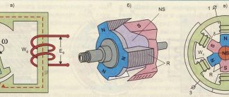
Main components of the inverter: rectifier, DC link, inverter
Rice. 1. Schematic diagram of the inverter
The rectifier is built using rectifier diodes or, less commonly, using a diode-thyristor circuit. Let's focus on the simplest - diode rectification.
Three-phase mains voltage with a frequency of 50 Hz and a voltage of 380 V is supplied to the input of the rectifier. After rectification, we get a pulsating voltage; it already has a certain kind of pulsation, but is not yet constant. The voltage becomes constant after the DC link enters and the ripples are smoothed out. Between the rectifier and the DC link there is a so-called precharge resistor.
Precharge resistor
limits the charging current of the capacitors at the first moment of time, thus protecting the rectifier diodes and the network from a large current surge. As the capacitor charges, this resistor turns off and does not take part in further operation.
DC link
As a rule, it is a set of capacitors of fairly large capacity. The task of this element is to smooth out voltage ripples as much as possible and bring it to a constant value. In a normal situation, when the mains AC voltage is 380 V, the value at the rectified DC link is 540 V. If the mains voltage is higher or lower, the value of the rectified voltage increases or decreases proportionally.
How to connect and configure the inverter
The connection can be made to both three-phase (380 V) and single-phase networks (220 V). When joining, the following actions must be taken (for both options):
- install a circuit breaker in the phase circuit in front of the converter (single-phase or three-phase switch);
- connect the outputs of the inverter phases to the contacts of the electric motor windings, previously connected in a “star” or “delta” (marked in the operating instructions for the frequency converter);
- connect to the device and place the inverter control panel in an accessible place.
Connecting the inverter to a three-phase network
Important! The currents of circuit breakers are selected according to the phase current (Iph) for a three-phase network and three times Iph for a single-phase network.
Connecting the inverter to a single-phase network
After the circuit is assembled, the motor shaft rotation regulator is removed to the minimum position. The following is done:
- turn on the machine and supply power;
- the switching on is detected by the indication of the LEDs on the panel (initial readings);
- then press the “RUN” button briefly (the start will be carried out according to the “default” parameters programmed by the manufacturer);
- slow rotation of the shaft in the desired direction indicates correct adjustment, otherwise change the direction of movement using the “reverse” option;
- after start-up, the desired rotation speed of the electric motor shaft is set.
Attention! It is possible that the display shows the frequency of the supply voltage (Hz) instead of the frequency at which the shaft rotates (rpm). These two quantities should not be confused.
Structure and features of the inventory
After the rectifier, the voltage is supplied to the inverter. The inverter is the most complex and important part of the frequency converter. From the output of the inverter, the signal goes directly to the electric motor. The voltage form at the inverter output is a set of rectangular pulses of different widths and a certain duration. This is how the power part of the frequency converter is built.
The device circuit also includes low-current circuits that help the interaction of all the main parts of the inverter. In particular, there is a central processor, which is, in essence, the brain of the converter and controls both the operation of the inverter and other parts of the device. The processor receives information about the output current from current sensors located on the output circuits of the inverter. The signal from the current sensors is processed, and the processor then generates a control algorithm so that the converter can operate under user-specified conditions. There is also a power supply for its own needs; it powers both the processor part and the part responsible for measuring the output current and measuring the voltage on the DC link. In addition, there is a block of driver chips, which in turn control the transistors of the inverter part, and a number of auxiliary elements.
Rice. 2. Schematic diagram of the inverter
Let's consider the basic design of the inverter part. The main elements of the power part of the inverter are IGBT transistors - powerful, specially designed for operation in switching mode. This is a hybrid of field-effect and bipolar transistors. The control part is an insulated gate (like a field gate), and the power part replicates the bipolar device, which has a collector-emitter.
Power elements are produced in the form of a dual module, consisting of two power transistors connected in series. Each of the transistors is shunted by a diode in the opposite direction. Since the output must have 3 phases, the inverter design has 3 arms (see Figure 2).
Rice. 3. Equivalent circuit of transistors
To better understand the principle of operation, consider an equivalent circuit where each transistor is replaced by a conventional switch. The diagram (Fig. 3) shows 6 switches (transistors) and an electric motor.
Let's study how output currents are formed in the motor windings. The central processor is responsible for controlling the transistors (switches in the diagram). It switches them strictly according to a specific program, which is initially set by the algorithm of its action.
The diagram shows the operation of keys No. 1, No. 4, No. 6. Please note that it is strictly forbidden to have a situation where both the upper and lower keys are closed in one arm - this will result in a short circuit and failure of the product. In the situation shown in the diagram, current flows through open switch No. 1, then enters winding A of the electric motor, exits windings B and C, and through open lower keys No. 4 and No. 6 goes to the negative link.
In order to change the current in winding C, you need to switch the switches of the middle arm. The current will still flow through open switch No. 1, and will go through winding B and switch No. 6 to the negative arm. In this case, at the same time, through closed switch No. 3, the incoming current through winding C goes negative. By changing the position of the open and closed keys, you can change the current in the motor windings. If this is done according to a certain program, you will get a variable current, as when the engine is running from the mains, that is, there will be a smooth flow of one phase to another.
Rice. 4. Current flow in the inverter
Now, instead of a simplified circuit with switches, let's consider how current flows in a circuit of transistors using the example of a real inverter (Fig. 4). At its core, this process is no different from the key mode discussed earlier, except that we are dealing with a real motor, which, in principle, is an inductive load.
At the moment the key is closed, the inductance of the motor will not allow the current to stop instantly due to the phenomenon of self-induction. This residual current is extinguished by reverse diodes, which are connected to closed transistors (see Fig. 4), i.e. at the moment of turning off (closing) the transistors, the residual current flows through the freewheeling diodes, thus preventing voltage surges on the switch.
But since the transistor acts as a switch, it can either supply full voltage to the motor or not supply it at all. In practice, it is necessary to obtain a certain smooth voltage of a sinusoidal shape, variable both in magnitude and frequency, in order to be able to control the rotation speed of an asynchronous motor.
Frequency converters
Frequency converters are electronic devices that are used to convert three-phase or single-phase AC mains voltage with a frequency of 50 (60) Hz into three-phase or single-phase voltage with a frequency from fractions of Hz to hundreds of Hz, and in some cases up to thousands of Hz.
Frequency converters are used to smoothly control the speed of an asynchronous electric motor or synchronous motor by creating an electrical voltage converter of a given frequency at the output. In the simplest cases, frequency and voltage regulation occurs in accordance with a given V/f characteristic; in more advanced converters, so-called vector control is implemented. Our range includes frequency converters (Intek SPK and SPE), in which, in addition to the usual modes (V/f and vector), there is a mode in which the voltage and frequency at the output of the converter can be adjusted independently of each other. In SPK series converters it is possible to connect an encoder as a feedback sensor. Frequency converters consist of a rectifier (rectifier bridge), which converts alternating current of industrial frequency into direct current, and an inverter, which converts direct current into alternating current of the required frequency and amplitude. The output transistors (IGBTs) are switched according to a complex algorithm (the so-called pulse-width modulation - PWM) mode is used. The output voltage is formed from the “cut out” sections of the DC link voltage. As a rule, the converter provides power to the electric motor with this pulse voltage. Through the use of frequency regulation, it becomes possible to control the performance of process equipment, which has a positive effect on its functionality and energy efficiency indicators, as well as operational reliability. If the cable connecting the converter and the motor is of considerable length, output current pulses occur due to the electrical capacitance of this cable. To protect the converter from these impulses, a choke is sometimes placed between it and the engine. During their operation, frequency converters create higher harmonic currents in the supply network, which leads to a deterioration in the quality of electricity. To protect the network from electromagnetic interference arising from the operation of power transistors, an electromagnetic compatibility (EMC) filter is installed at the converter input. If the power supply network is “clogged” with switching voltage surges, and also to reduce the effective value of the supply current, an AC mains choke is installed in the input power circuit of the converter.
purchase frequency converters Intek frequency converters from our company. If you have questions about choosing a model, contact our technical service and get advice. If you have special requirements, our company is ready to analyze them and recommend the necessary equipment. When operating or servicing the frequency converter, all safety precautions must be observed. Remember that the device contains electrolytic capacitors that retain a charge for a long time even after being disconnected from the network. Therefore, before servicing the frequency converter, it is necessary to wait until they are discharged. The design of frequency converters contains elements that are afraid of static electricity. In particular, this applies to the microprocessor control system. Therefore, the inverter must be properly grounded not only to protect operating personnel from electric shock, but also to protect internal components from static electricity.
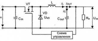
Operating principle of a frequency converter based on IGBT transistors. The converters use double conversion of electrical energy: an input sinusoidal voltage with a constant amplitude and frequency is rectified in a rectifier, smoothed by electrolytic capacitors, and then again converted by the inverter into an alternating voltage of variable frequency and amplitude. A typical frequency converter circuit is shown in the figure below. The lower part of the figure shows voltage graphs on the main elements of the converter.
After the rectifier, a resistor is installed, which performs the function of limiting the charging current of the capacitors at the moment the converter is connected to the network. A few seconds after switching on, this resistance is shunted by relay contacts (sometimes a thyristor is used for shunting purposes). From the output of the capacitive filter, a constant voltage is supplied to the input of the inverter. The inverter of modern converters is based on power bipolar transistors with an insulated gate IGBT. The inverter converts direct voltage into three-phase (or single-phase, if the converter is designed to power single-phase electric motors) pulse voltage of variable amplitude and frequency. Based on signals from the control system, the corresponding power transistors of the inverter connect the windings of the electric motor to the positive and negative poles of the DC link. The duration of connection of each winding is different over time. The greatest pulse width should be in the middle of the half-cycle, and towards the beginning and end of the half-cycle it decreases. Thus, the control system provides pulse width modulation (PWM) of the voltage applied to the motor windings. The voltage amplitude and frequency are determined by the transistor control system. At a high PWM carrier frequency (1...15 kHz), the motor windings act as a filter due to their inductance. Therefore, the currents flowing through them are smoothed out and have an almost sinusoidal shape. Thus, a three-phase (or single-phase) alternating voltage of variable frequency and amplitude is formed at the output of the frequency converter.
Economic efficiency of using a frequency converter Frequency converters offered by our company can be used in industrial systems where it is necessary to maintain a certain technological parameter at a given level. This parameter is measured by a corresponding sensor, the signal of which is supplied to a special input of the converter. Often the solution to this problem is used in systems where it is necessary to maintain pressure in the main pipeline. In this case, the pump electric motor is powered by a frequency converter, which sets the pump rotation speed at which the pressure in the line is stabilized. The payback period after installing the converter into the system is usually less than six months. Economic benefits are achieved due to a significant reduction in energy consumption compared to a system where the pressure is regulated, for example, by a valve or bypass valve. The greatest economic efficiency of using an inverter is achieved if the ventilation or water supply system is underloaded most of the time. Such periodic underload is typical of these systems. For example, in the daily water flow curve, as a rule, there are two clear maxima - in the morning and in the evening. Based on these maximums, the power of the main pump is selected. The rest of the day, the pump operates at low load. It is at this time that the inverter allows you to reduce power consumption.
In the range of products offered to our customers, all inverters have a built-in regulator, which allows the use of this converter to automatically maintain water pressure or air flow at the required level. The built-in voltage source (24 V DC) allows you to provide power to the process sensor without the use of additional units.
Why are chokes needed when working with frequency converters? Input chokes reduce the likelihood of damage to the converter due to switching surges or large phase voltage imbalance (>2%) in the power line. Also, input chokes serve to bring the shape of the converter input current closer to a sinusoid, which, in turn, reduces the effective value of this current and the heating of the wires.
Surges can be caused by the following factors:
- Installation of powerful power electronic equipment near the drive (for example: DC and AC drives, industrial rectifiers, power factor improvement units, etc.).
- Electric motors started directly from the network using magnetic starters or soft starters.
- Accidents in the power supply system.
- Using welding equipment near converters.
Failure of converters due to pulse overvoltages or poor-quality supply voltage are not covered by warranty.
Output chokes must be used in cases where the length of the power cable connecting the converter and the motor exceeds the value specified in the operating instructions for this device. Also, output chokes are installed if the converter powers several motors. A distinction is made between connecting loads in a “fan” or “loop”. With fan-out, all motor cables are connected at the output of the converter. In this case, the installation of output chokes is mandatory. It should be noted that output chokes significantly reduce the likelihood of converter failure during short circuits in the motor circuit, and especially during short circuits to ground.
What is scalar and vector control in a frequency converter? Scalar control (or V/f frequency control) assumes the following algorithm for the operation of the converter. Depending on the task, a voltage of a certain frequency and magnitude is generated at the output of the converter. This voltage is intended to power the motor windings. However, there is no control over how the motor actually rotates. The motor is supposed to spin "correctly". Only the current level is controlled so that it does not exceed certain values that are dangerous for the motor and converter. The lower limit for engine speed control with this algorithm is usually about 10% of the rated speed. The name “scalar control” came into technical use to contrast it with the vector mode of operation of the converter. Vector control without a speed sensor (so-called SVC control - Sensorless vector control) is an improved method of controlling asynchronous motors. With this control, the converter microprocessor calculates the magnetic flux vector, speed and torque values of the connected electric motor. Calculations are performed using measured motor voltage and current data. In order for the calculations to be correct, it is also necessary to use data on the parameters of the connected electric motor (its resistance, inductance, etc.). Some of the data is entered into the converter’s memory from the nameplate (“nameplate”) of the motor; the values of other parameters are determined by the converter itself, using a special preliminary procedure for tuning to a specific motor. During operation, after the microprocessor has made calculations, the calculated speed or torque values are compared with the specified values and, based on their mismatch, the voltage supplied to the motor is generated using the inverter converter. All vector converters can operate in both vector and scalar modes. The benefits that SVC vector control provides are:
- Significantly wider range of rotation speed control compared to scalar control. The range can reach a value of 1:100. That is, when the speed is set to 1% of the rated value, the rotation of the motor will be maintained regardless of what load it experiences. For low-power engines (up to 0.55 kW), this range is usually slightly lower - 1:50.
- The motor current, and, consequently, the power loss in it, at low rotation speeds is less than with scalar control.
- Possibility of operation in the mode of regulating the torque on the shaft of an asynchronous electric motor (at speeds different from zero).
Regardless of which mode, vector or scalar, is used by the converter to control an asynchronous motor, it is always necessary to ensure cooling conditions for this electric motor. A situation with engine overheating can occur during long- term operation at low speeds (up to 50% of the rated speed). In this case, it is necessary to install forced cooling of the engine using an additional fan. It should be remembered that in vector mode, a group of motors cannot be connected to the converter, and when replacing a motor, the converter must be configured for this specific motor. Some of our frequency converters Intek frequency converters with a power of more than 5.5 kW allow you to work in mode with a feedback sensor (encoder, resolver) on the motor shaft. This allows the drive to operate with a speed control range of 1:1000.
Braking Resistor A braking resistor is needed to dissipate the energy that flows from the motor to the inverter. The engine, in this case, operates in generator mode. This mode can occur when braking the inertial masses of the load or when lowering the load in a lifting and transport mechanism. In these cases, the engine seems to be ahead of the speed at which it should rotate. The load “pushes” the engine rotor and helps it rotate. The energy flowing from the motor to the converter accumulates in the DC link of the converter and can lead to unacceptable overvoltage on the capacitors. To prevent this from happening in converters, as a rule, there is an additional braking transistor (braking chopper, 7th transistor), which at the right time connects the braking resistor to the DC link. And the “excess” energy, heating the resistor, turns into heat.
Selecting a frequency converter for a specific application When selecting a frequency converter for a specific motor, it is necessary that the rated current of the frequency converter is not less than the rated current of the motor. The output voltage of the frequency converter must match the motor voltage. It is also necessary to check the maximum permissible short-term current supplied by the frequency converter to ensure the required overload capacity of the motor. Below are examples of selecting a converter based on overload capacity. (In each individual case, the issue must be resolved individually).
| Name of application area of adjustable drive | Converter overload capacity | Notes, recommendations |
| Centrifugal pumps, fans | 120% within 1 minute | The frequency converter can be taken with a rated power one step below the motor power and switched to light load mode |
| Transport mechanisms, conveyors, the vast majority of other applications | 150% within 1 minute | — |
| Extruders, main drive of metal cutting machine, etc. | 200% within 1 minute | The frequency converter should be taken with a rated power one step higher than the motor power and the current protections and current limits in the converter should be configured according to the data on the motor nameplate and the required overloads |
Features of a frequency converter for a high-speed electric spindle Since high-speed electric spindles operate at high frequencies of 200-2000 Hz, to ensure the operation of the motor it is necessary that the carrier frequency (PWM) of the frequency converter be an order of magnitude (10 times) higher than the rated frequency of the motor. For example, if the spindle has a nominal frequency of 400 Hz, then the frequency converter must have a PWM carrier frequency setting of 4 kHz or more. It should be remembered that with a high PWM frequency, energy losses in power transistors increase and in some cases, an increase in the installed power of the converter is required.
Limit operating frequencies of an asynchronous drive Below we will talk about a drive consisting of an asynchronous motor with a rated frequency of 50 Hz and a frequency converter. In practical applications, the converter output frequency is rarely raised above 70 Hz. This is primarily due to the fact that the motor rotors at the factory are balanced (if they are) at a frequency of 50 Hz and a large increase in frequency can lead to unacceptable vibrations and even mechanical damage to the motor and its windings. Also, at increased rotation speeds, heat losses in the steel increase. However, due to the increased intensity of fan blowing, these losses, as a rule, do not lead to overheating of the engine. It should be remembered that the torque developed by the engine drops at rotation speeds higher than the rated frequency. This is due to a “lack of” voltage at the output of the converter and, as a consequence, to the so-called demagnetization of the asynchronous motor. Approximately, we can assume that the reduction in torque occurs in inverse proportion to the increase in frequency above the nominal value. (That is, at 70 Hz the motor torque is approximately 72% of its rated value).
PWM operation algorithm
Next, let's look at how the output voltage is generated using the pulse width modulation (PWM) method. For example, let's take a certain hydraulic model that will help us understand what is happening.
Rice. 5. Hydraulic model
Let us imagine that there is a series of containers. Each has holes at the bottom. Using a certain device that produces droplets of water of certain sizes with a constant frequency, we begin to fill these vessels. It is clear that where the droplet size is small, the liquid level will be set at a low level, and the larger the droplet size, the higher the level of the liquid in the vessel will be. By choosing the droplet size in a certain way, you can obtain the envelope of these levels (see Fig. 5). Thus, it was possible to depict a static picture, which gives an understanding of the process, how it is possible to make something similar to analog ones from discrete parts.
Now let's move on to working in dynamics. Let's imagine that there is only one vessel, but we change the size of the droplets with which it is filled. At the bottom of Fig. Figure 5 shows the process at this moment in time - along the x-axis time (t), along the y-axis voltage (U) or, in other words, the water level in the vessel. As the droplet size changes, so does the average liquid level, rising and then beginning to fall. This is already a dynamic process. Now we draw an analogy with electricity.
Figure 6. Converting a discrete signal to an analog signal
In Fig. Figure 6 clearly shows what happens to a discrete signal if we open the switch and close it at a certain frequency and for a certain time: the wider the transistor opening pulse, the higher the average voltage level (red signal envelope).
Let's introduce a few parameters and explain them.
- The period of a PWM signal is the time between pulses. The parameter is strictly specified and does not change (from the previously described example, this is when the droplets all drip with the same frequency, only of different sizes).
- The PWM modulation frequency is inversely proportional to the duration of the period; this is what we have as one of the parameters when programming a frequency converter. Determines the pulse repetition rate at the output of each channel of the IGBT module.
- Pulse duration (t-pulse). It is determined by the processor itself. That is, the processor, depending on the specified value of the output signal, currently determines for how long each key needs to be opened. If we consider the total period of change of these oscillations, we will have a period of the output frequency (t-output). This is the output frequency that we will have at the output of the frequency converter. The engine rotation speed directly depends on it.
The frequency converter ensures that the motor is not overloaded and the voltage supplied to it at this frequency is proportionally decreased or increased. He himself determines the required opening time for each key, that is, by determining the t-pulse. And this situation occurs simultaneously on three channels leading to the output of the converter to the electric motor.
It can be seen from the figure that the more often the pulses occur, the closer the voltage shape will be to sinusoidal.
Classification of frequency converters
A technical device that converts an alternating voltage of one frequency at the input into an alternating voltage that varies according to a certain law, but with a different frequency at the output is called a frequency converter (FC). There are two types:
- Direct
- Two-link
Direct - this is a reversible thyristor converter. Its main advantage is that it connects directly to the network without additional devices.
Two-link - are a transistor or thyristor converter. But their main difference from direct converters is that for the correct and safe operation of the inverter, a DC voltage link is required. Accordingly, to connect them to general industrial networks, a rectifier is required. As a rule, they are manufactured complete (the inverter and rectifier are supplied together and operate from the same control system).
Frequency selection criteria
In practice, the PWM frequency can be set by the user, usually in the range from 1 to 15 kilohertz. In order to obtain a voltage more or less close to a sinusoidal shape, the PWM frequency should be 20-30 times the maximum output frequency that you want to obtain.
You can choose the PWM frequency arbitrarily for your specific task. There are several parameters that determine the choice.
Fig.7. Parameters influencing the choice of PWM frequency
1. Cable length to motor. The longer the cable, the lower the PWM frequency can be set. For example, if your cable length is 100 meters or more, then there is no point in setting the PWM frequency to more than 2.3 kilohertz, otherwise there will be large losses and wasted power at this length.
2. Acoustic engine noise. When the motor is powered by a frequency converter, extraneous noise is heard. It depends exactly on the PWM frequency that you set. The higher it is, the higher the pitch of the sound. If the purity is set to more than 8.10 kilohertz, the noise is practically inaudible. At lower frequencies (1.3.5 kilohertz) this noise is significant and causes discomfort.
3. Maximum output frequency. Most motors use a maximum inverter output frequency of 50Hz, so here the PWM frequency must be at least 20 times higher. Here you can set the frequency of 1, 2, 3, 5 kilohertz from the entire range.
If you are using a high-speed motor, for example a 400-Hz motor, then you should not set the PWM frequency to 1.3.5 kilohertz: the output will not be a sinusoid. For such high-speed motors, the PWM frequency is selected as high as possible for a given inverter, say, 15 kilohertz.
4. Heat generation from the inverter part of the converter. This is due to the fact that the IGBT transistors that generate the output voltage are not ideal and are subject to heating during operation. In order to effectively remove heat, it is necessary to use appropriate radiators and cooling fans. The greater the heat generation in this inverter part, the more powerful cooling devices must be used.
Electric drive control methods
To solve problems of speed and torque control in a modern electric drive, two main methods of frequency control are used:
- scalar control;
- vector control.
An asynchronous electric drive with scalar control is by far the most common. It is used as part of drives of pumps, fans, compressors and other mechanisms for which it is important to maintain either the speed of rotation of the motor shaft (in this case a speed sensor is used) or a process parameter (for example, pressure in a pipeline, in which case an appropriate sensor is used).
The basic principle of scalar control is changing the frequency and amplitude of the supply voltage according to the law U/fn = const, where n≥1. The specific type of dependence is determined by the load requirements imposed on the electric drive. Typically, frequency is taken as an independent effect, and the voltage value at a given frequency determines the type of mechanical characteristic, the value of the starting and critical torques. Scalar control ensures the constant overload capacity of the electric drive regardless of the voltage frequency, however, there is a decrease in the torque developed by the motor at low frequencies (at f<0.1fnom). The maximum range of control of the rotor speed at a constant torque for electric drives with scalar control reaches 1:10.
The scalar control method is relatively simple to implement, but has two significant disadvantages. Firstly, in the absence of a speed sensor on the motor shaft, it is impossible to regulate the shaft rotation speed, since it depends on the load. The presence of a speed sensor solves this problem, but the second significant drawback remains - it is impossible to regulate the torque on the motor shaft. On the one hand, this problem can be solved by installing a torque sensor, however, such sensors have a very high cost, often exceeding the cost of the entire electric drive. But even with a sensor, torque control is very inertial. Moreover, with scalar control it is impossible to control both torque and speed at the same time, so you have to choose the value that is most important for a given technological process.
To eliminate the shortcomings inherent in scalar control, SIEMENS proposed a vector control method back in 1971. The first versions of electric drives with vector control required the use of motors with built-in flow sensors. This significantly limited the use of such drives.
In modern electric drives, the control system includes a mathematical model of the engine, which allows one to calculate the torque on the shaft and the speed of rotation of the shaft. In this case, only motor stator phase current sensors are necessary. Thanks to the special structure of the control system, independent and almost inertia-free control of two main parameters is ensured - torque on the shaft and rotation speed.
To date, two main classes of vector control systems have been formed - sensorless systems (without a speed sensor on the motor shaft) and systems with speed feedback. The use of one or another vector control method is determined by the area of application of the electric drive. For small speed ranges (no more than 1:100) and requirements for speed maintenance accuracy of no more than ±0.5%, sensorless vector control is used. If the shaft rotation speed varies within a wide range (up to 1:10000 or more), there are requirements for high accuracy of maintaining the rotation speed (up to ±0.02% at rotation speeds less than 1 Hz) or there is a need to position the shaft, and also, if necessary To control the torque on the motor shaft at very low speeds, vector control methods with speed feedback are used.
When using vector control, the following advantages are achieved: high accuracy of speed control even in the absence of a speed sensor; smooth, jerk-free engine rotation at low frequencies; the ability to provide rated torque on the shaft at zero speed (with a speed sensor); quick response to load changes: during sudden load surges there are practically no speed jumps; ensuring an engine operating mode in which heating and magnetization losses are reduced, and therefore the engine efficiency is increased.
Along with the obvious advantages, the vector control method also has some disadvantages, such as high computational complexity and the need to know the motor parameters. In addition, with vector control, speed fluctuations at a constant load are greater than with scalar control. It should be noted that there are areas in which it is possible to use only scalar control, for example in a group electric drive, where several motors are powered by one converter.
Energy losses in a frequency converter and ways to reduce them
Let's consider the issue of heat generation in the inverter part of the converter. What determines the losses of a transistor?
Fig.8. Energy loss
Let's take a conventional IGBT transistor, which is connected to a circuit with a voltage of 500 volts, limiting the resistor.
Closed state: there is no voltage at the gate, the voltage at the collector is equal to the mains voltage, there is no current, leakage is negligible, and there is no heat generation. We open the transistor using a voltage of 10 volts at the gate, this is the standard voltage for almost all transistor modules. The transistor does not switch to the open state instantly; each transistor has a parameter called on time or off time. A typical value for the most common transistors is 0.2 microseconds. The time is short, but during this time there is both a voltage on the transistor crystal, which quickly drops, and an increasing current value, which also does not increase instantly. At this point, losses occur. And the higher the PWM frequency, which we talked about earlier, the more often the transistor turns on and off, the more heat is generated due to switching losses.
When the transistor has opened, a static mode has been established for some short time, heat generation continues: it occurs due to the fact that at the moment of the opening state, the voltage on the transistor is also not zero, it is determined by losses on the crystal in the open state. Its typical value is 1.5 volts. It may vary slightly depending on the manufacturing technology of the transistor, etc.
At this moment, heat generation also exists, but we cannot do anything about the losses in the on-state, the maximum is to use transistors with a lower voltage in the on-state. We can combat switching losses by reducing the PWM frequency. This is useful if the inverter is located in a closed cabinet, where it gets hotter. By lowering the PWM frequency, we can reduce losses on the converter and reduce its temperature.
The total loss of the frequency converter in the form of heat is about 3%.
Rectifier losses occur through open diodes. The voltage drop across the open diode, as well as the rectified current flowing through it, lead to its heating. The DC link, consisting of large-capacity electrolytic capacitors, also heats up because the charge and discharge process is constantly occurring. Losses also include the frequency converter’s own needs: the operation of cooling fans, electronic circuits, secondary power sources, and so on.
How to choose a frequency generator
There are several criteria by which a device is selected.
By power
The power of the converter (P) should be slightly greater than the electrical power of the motor it will control. The electrical power that the motor will consume is equal to the product of voltage and current (V*A). The frequency driver is selected with a 15-20% power reserve.
Nameplate on the electric motor
Mains voltage
The choice of regulator depends on what voltage will be the supply (380 V or 220 V). The value of Upit is indicated in the technical data sheet of the device.
Frequency control
The frequency adjustment interval of the converter, declared by the manufacturer, must allow the rotation of the shaft of the attached electric motor to be adjusted within the range of its speed characteristics.
Digital inputs
Entrances are required. They are needed to issue (enter) commands. With their help, you can change the converter parameters and its state.
Digital inputs
Ratio of price and number of pins
You can choose a frequency converter based on the price based on the number of functional pins. Not only the cost, but also the ease of connection, control, configuration and adjustment depends on their quantity.
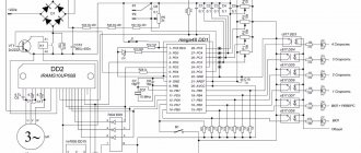
Delta VFD-B inverter pinout diagram
Overloads and control room
The control bus (CB) is selected for a specific inverter. A good option when purchasing would be a control room, which has a sufficient supply of pads (connectors) for connection. This will allow you to connect additional equipment and overload protection devices to the device in the future. Assembling a frequency converter with your own hands will help you take into account all the necessary qualities.
3.1. Selection of element base
There are no special requirements for the reliability, accuracy and speed of the circuit, so the only criterion for selecting elements is to ensure the specified operating parameters of the device. In accordance with this, the following element base was selected:
— One-shot based on the K156AG1 microcircuit
— Integrator based on the K140UD20 microcircuit
— Zener diode KS210B2
— Capacitors with negative TKE
— Resistors with positive TKE