Three-post corner support of a 500 kV power line.
How to determine the voltage of a power line by the appearance of the support, the number of wires and the length of the insulators? I started asking this question around the time the power lines started creeping into my photo collection. After reading various texts on the Internet, studying power grid maps and various other sources, even looking at the PUE a couple of times, I decided that it was time to write my own version of the instructions “How to determine the voltage on power lines.” With sparkling humor and pictures.
To begin with, it should be noted that the voltage on power lines can be found out from plates with various information, or simply inscriptions that can usually be found in one form or another on power line supports. But we are not here to read the inscriptions on the signs.
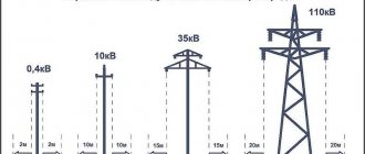
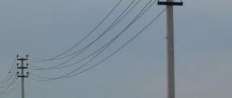
Lines 0.4 kV or 380 V
Wooden pole carrying 380 volts
Usually these are low poles, often wooden, 4 thin wires, small white porcelain insulators without ribs. Three wires form one three-phase circuit, the fourth wire is neutral. These are “last mile” power lines, so to speak, they directly power country houses, cottages, and various small consumers in rural areas. There is also a single-phase version of such power lines, with two wires, zero and phase, with a voltage of 220 volts.
Nothing special, overall.
Cable power lines
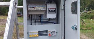
Electricity metering cabinet: functions, classification, selection
What is a cable power line? This type of power lines differs from overhead lines in that the wires of different phases are isolated and combined into a single cable.
According to the conditions of passage
According to the conditions for passing the CL, they are divided into:
- Underground;
- Underwater;
- By buildings.
Cable structures
In addition to the fact that the cable can be located in water or land, part of it must pass through cable structures, which include:
- Cable channels;
- Cable camera;
- Cable mine;
- Cable well;
- Double floor;
- Cable gallery.
Cable well
This list is incomplete; the main difference between cable structures and others is that they are intended exclusively for installing cables along with fastening devices, power couplings and branches.
By type of insulation
The most widely used cable lines are those with solid insulation:
- Polyvinyl chloride;
- Oil-paper;
- Rubber-paper;
- Polyethylene (cross-linked polyethylene);
- Ethylene-propylene.
Liquid and gas insulation are less common.
Lines 10/6 kV
The poles are approximately the same as for 0.4 kV lines, usually concrete, but can also be wooden. There are usually 3 wires (one circuit), slightly larger insulators, green glass or black porcelain, with ribs. 2 plates can be used as insulators.
10 kV lines are more common than the dying out little by little 6 kV lines. 10 kV lines supply energy to small villages, or redistribute energy in larger settlements, for example, they go from substations 110/10/6 to transformer substations. Also, these are precisely 10 kV lines that usually stretch along railways; they are used there to power signaling devices and from them well-known branches go to package transformer substations.
10 kV line pole with transformer NOL-10
Two 10 kV supports with disconnectors
10 kV power line and branch to KTP
Double circuit end support 10 kV
On the railway (on the sides)
Scheme maps of electrical networks in 2GIS
Have questions)?
Need to know more? Want to buy! Get help via the Hotline. The system for generating map diagrams of electrical networks is a new stage in the development of programs for calculating distribution networks, not only for design, but also for accounting and monitoring the status of networks by their owners and service organizations.
There are two main implementations of LineGeo:
1. Display of all power lines 0.4 - 500 kV and substations with basic characteristics, without calculations. 2. The same with calculations of 0.4 and 10 kV networks for voltage losses and short circuit currents, see programs LineNet04 and LineNet10Cad .
The resulting map diagram of electrical networks looks like this (example for a cottage community in Novosibirsk):
Purple color - 10 kV, gray - 0.4 kV, blue - 110 kV
The voltage color corresponds to STO 56947007-25.040.70.101-2011.
Here, in the demo version (power supply of a cottage community), the design diagram of 0.4 and 10 kV lines is shown. Almost all of the lines have been installed, some of the cottages have been built and occupied, some are either under construction and are already consumers, or are still represented by plots of land for development. Thus, the project development can be considered a plan for the long-term development of a cottage community. Leaving only built and under construction cottages on the map, we will get the real, current position and, by saving the map to a new LineGeo file, we can track current changes, plan and take into account the connection of new consumers.
Conclusion. For the same territory it is possible to: 1. Have a map of the current power supply scheme. 2. Plan and show promising development.
Networks of any voltage can be drawn on maps, therefore current and future accounting of 35-500 kV lines and substations with a description of the main characteristics of the circuit elements, showing the supports, their codes and numbers is necessary for all network owners and service organizations.
The map view is as uncluttered as possible, some symbols are turned on/off. the main characteristics appear only in pop-up windows or in the context menu “Properties” of the diagram element.
The LineGeo system provides calculations only for 0.4 and 10 kV distribution networks, which are the main ones in the power supply of cities and towns. Only external power supply up to inputs to consumers is considered.
The demo version of LineNetGeo (LineGeo) was created on the 2GIS map of Novosibirsk. Download the archive, unpack and run the demo installation module SetupLineGeoDemo(v 1.0).exe. The presence of the 2GIS application and a map of Novosibirsk will be checked on your computer, after which, if necessary, following the instructions, you need to install them. The demo version of LineGeo will be recorded in the 2GIS application folders. LineGeo is not registered in the registry and can subsequently be uninstalled or deleted manually.
After installing the demo version, launch or restart 2GIS. A new tab will appear in the menu, LineGeo.
In February 2015, at the request of Tyumenenergo, a second demo version of the application of the system for generating maps - diagrams was released for the city of Surgut. Installation instructions are the same.
SetupLineGeoDemo(v 2.0).exe
This part of the entire map shows 0.4, 10 kV lines, 10/0.4 kV transformer substations (bottom), 110 kV lines and substation, 500 kV lines and substation (top). When you click on all circuit elements, windows with characteristics of the circuit elements appear.
Details in Readme_DemoLineGeo and User Manual (Description of system. Description of application), which are installed along with the demo version.
linecross.ru
35 kV lines
They are found, as a rule, only in rural areas, where they feed small 35/10/6 kV substations. In cities, 110 kV lines are usually used instead.
35 kV lines are noticeably different from 10 kV - the wires are more widely separated from each other, the insulators are larger, as a rule these are 3-5 plates. The supports are higher, and in addition to wood and concrete, they can also be made of metal structures, especially if there is more than one chain on the support.
Double circuit support 35 kV
Substation 35/10/6 kV
Determining voltage by appearance
The next stage is determining the power of overhead lines.
How can you find out the voltage on a power line by its appearance? The easiest way to do this is by the number of wires and the number of insulators. The easiest way is to determine by insulators.
There are overhead lines of different voltage classes. Let's look at each one in turn.
Power lines of 0.4 kilovolts (400 Volts) are low-voltage, found in all populated areas. They always use porcelain or glass pin insulators. The supports are made of reinforced concrete or wood. There are two wires in a single-phase line. If there are three phases, there will be four or more conductors.
Next come power lines for 6 and 10 kilovolts. Visually they are indistinguishable from each other. There are always three wires here. Each uses two porcelain or glass pin insulators or one of a higher value. These routes are used to supply power to transformers. The minimum distance to current-carrying parts here is 0.6 m.
Often, in order to save money, they combine the suspension of 0.4 and 10 kV conductors. The security zone for such routes is a distance of 10 m.
In power lines with a voltage of 35 kV, suspended insulators are used in quantities of 3 to 5 pieces in a garland for each of the three phase wires.
Typically, such air routes do not pass through urban areas. The acceptable distance is 0.6 m, and the security zone is defined as 15 meters. The supports must be reinforced concrete or metal, with current-carrying conductors spaced apart from each other at an acceptable distance.
In power lines with a voltage of 110 kV, each wire is installed on a separate garland of 6-9 suspended insulators. The minimum distance to the conductors is 1 meter, and the security zone is defined as 20 meters.
The material for the support is reinforced concrete or metal.
If the voltage is 150 kV, use 8-9 suspended insulators for each garland in the power line. A distance of 1.5 m to current conductors is considered minimal in this case.
When the voltage is 220 kV, the number of insulators used ranges from 10 to 40 units. The phase is transmitted over one wire.
The lines are used to supply electricity to large substations. The shortest distance to approach the conductors is 2 m. The size of the security zone is 25 m.
In subsequent classes of high-voltage power lines, a difference appears in the number of wires per phase.
If two conductors are installed per phase, and there are 14 insulators in garlands, you have a 330 kV main line.
The minimum distance to live parts in it is considered to be 3.5 m. The necessary increase in the security zone is up to 30 m. The material for the supports is reinforced concrete or metal.
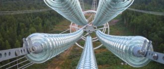
If a phase is split into 2-3 conductors, and there are 20 suspended insulators in garlands, then the overhead line voltage is 500 kV.
The security zone in this case is limited to 30 meters. A distance of less than 3.5 m to the wires is considered dangerous.
In the case of a phase division into 4 or 5 conductors, the connection of which is ring or square, and the presence of 20 or more insulators in the garlands, the overhead line voltage is 750 kV.
The protected area of such routes is 40 m, and approaching live parts closer than 5 m is dangerous to life.
Russia has the only power line in the world with a voltage of 1150 kV. The phases in it are divided into 8 wires each, and the garlands contain 50 or more insulators.
You should not approach this route more than 8 meters. You can see such a high-voltage line, for example, on the section of the Siberia - Center highway.
You can get detailed information about any overhead line and its location on an interactive map on the Internet.
Lines 110/150 kV
110 kV power lines are probably the most common type of power lines, especially in urban areas, after 10 kV, of course. They can be found both in the city and outside the city, or rather, it is generally difficult to find a place where they can not be found.
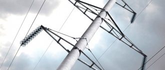
The 110 kV lines are already beginning to make some kind of impression, let’s just say that I associate the abbreviation transmission line with them in principle, although it is sometimes difficult to distinguish them from 220 kV lines. 110 kV lines are high supports made of metal structures or concrete, usually carrying 2 circuits (6 wires), single-circuit ones are also found, but less often. Insulators are always plates, 6-9 plates in a garland. I have never seen wooden supports for such stress, but they still exist. Each phase on 110 kV lines is made of one wire, i.e. no phase splitting is observed.
110 kV lines have a significantly larger security zone of 20 meters. There is also a new element - a lightning protection cable.
Regarding 150 kV lines, it seems that in Russia they are a little exotic, if they exist at all. At least this is the conclusion I came to by studying power grid maps, plates, and various similar documents.
110 kV power line supports near CHPP-2
110 kV power transmission line supports on the edge of the Tsaritsyno recreation center
Horned power transmission line support for 110 kV
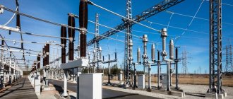
Typically, 110 kV lines connect large 220/110 (or higher) substations with smaller 110/10/6 substations, often located within urban areas. They can power railway traction substations, or, for example, small factories. For example, 110/10/6 kV substations look like this:
Power substation "Krasnogorskaya" 100/10/6 kV
Transformers 40 MVA
At the same time inconspicuous and fascinating. Unprepossessing - this is compared to what will happen next.
And then we have much more serious things going on...
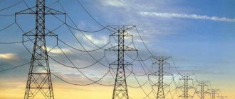
Power lines 220 kV
In appearance they resemble 110 kV, but larger, higher, and have longer strings of insulators - about 10-20 pieces, you’ll hesitate to count. There is an opinion that there is no phase splitting on such power lines, there is still 1 phase, this is 1 wire, but this opinion is inaccurate. The supports are also made of metal structures, much less often of concrete.
220 kV lines are found much less frequently than 110 kV lines. As a rule, they connect different settlements, regions, districts, and can have a significant length of up to several tens or even hundreds of kilometers. Like 110 kV lines, they usually run in two circuits, but single-circuit options also exist. Being near such lines, you can already hear a distinct crackling sound - corona discharges are taking their toll.
The security zone of a 220 kV cable line is 25 meters.
220 kV power line support - Dagomys substation
Double circuit tower 220 kV
HF suppressors 220 kV
Sign on the support
Supports of a two-tier structure
Types of power lines
Workers performing electrical installations have all the necessary knowledge and experience to help them competently, in compliance with all safety measures, carry out their work near power lines. However, such rules may be unfamiliar to the average person. However, any adult should have concepts related to electrical safety, because one day, such knowledge can save a life. To avoid electric shock, which in turn is under high voltage, you need to know some features regarding power lines. All Kazan electrical networks are classified in accordance with a certain set of parameters, namely:
- Low voltage. Basically, these are structures under “low” voltage up to 1 kV.
- Medium voltage. Such designs have a charge of up to 10 kV. Designed to support the life of, for example, one village.
- High voltage. Such power lines can be found near cities. Their power can reach up to 220 kV. The smallest is 110 kV.
- Ultra high. The level of electric current in such power lines reaches up to 500 kV.
- Ultra high. Their power can reach up to 1150 kV.
To avoid an accident, distances should be maintained along such structures. It doesn’t matter whether you are doing any work along power lines, or just happen to be close to them, it is important not to deny safety precautions. Staying at a minimum distance is a must for all those who find themselves directly near power lines. Otherwise, a breakdown of the air gap of the power line may occur, which in turn is fraught with consequences. Often, the installation of electricity is located in a security zone, which does not imply any construction of additional facilities and the constant presence of people.
Power lines 330 kV
It must be said that this is not a very common type of power transmission lines, and they can only be found in St. Petersburg, where the entire energy ring operates at a voltage of 330 kV, and, perhaps, even in Crimea.
Outwardly, they strongly resemble 220 kV lines, but they look somewhat larger, and have a clear splitting of the phase wires into 2 wires. There are also about 20 insulators in the garlands.
I was lucky enough to visit St. Petersburg once, so, in fact, here it is:
330 kV power line (left)
Design of overhead power lines
The design of overhead power lines is carried out in accordance with regulatory requirements, rules and standards: PUE (electrical installations), SNiP (design of overhead power lines), departmental and other acts.
Standardization of the vast majority of construction and installation work during the construction of overhead power lines, the structures used, devices, supports, materials, voltage parameters and other characteristics, and the obligation to coordinate projects limit the implementation of individual solutions. Therefore, the design of overhead power lines is usually standard, but allows for the adaptation of standard solutions to the actual conditions of installation and operation of power lines.
According to voltage standards, overhead power lines are distinguished:
- three-phase current up to 1000 V (1 kV);
- three-phase current above 1kV.
- direct current.
At least 3 wires are suspended on a three-phase power transmission line, forming one circuit. On DC power lines - at least 2 wires.
The project, based on a preliminary survey of the power transmission line construction area, analysis of climatic operating conditions, and requirements of the technical specifications, determines:
- Power supply diagram for power lines:
- power, voltage, redundancy;
- number of circuits (one, two or more);
- number of lines (one, two, several parallel) and supports.
- Type, materials and design (brand) and number of wires, lightning protection cables.
- Design climatic conditions for the operation of power transmission lines - ice (ice-frost), wind loads, temperature levels under given conditions and their influence.
- Method of installation (suspension) – type of supports, fastening, tension.
- Calculated parameters for the relative position of wires, grounded parts of supports, the surface of the earth, and ground objects. The main goal is to eliminate electrical discharges during overvoltages on power lines of a given voltage level.
- Span length. Critical spans of power lines. Dependence of voltage on various operating conditions (modes).
- Other parameters and their values in accordance with the Electrical Installation Rules (PEU).
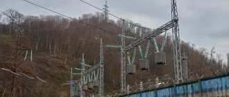
Power lines 500 kV
Three pyramidal supports of a 500 kV power line and interesting graffiti
This is where the real monsters begin, their very appearance inspiring greatness and awe. 500 kV power lines are large lines that usually connect power systems of different regions; the typical line length is about 200-300 km, although they can be longer.
The supports are very high, usually U-shaped or glass-shaped, always single-chain. Corner and tension supports are usually made of three separate pyramidal supports and have 3 garlands of insulators. There is phase splitting - 3 wires per phase, insulators consist of an average of 30 plates per garland. In the south of Moscow, by the way, in Butovo, you can find a 500 kV power line with a vertical phase arrangement and splitting into 4 wires.
In our country, not many facilities can operate at a voltage of 500 kV. Often (but not always), one such substation powers one large city, for example, Novosibirsk. Around the harsh Chelyabinsk you can count as many as 3 such substations, and near the vast Moscow there are already 10 of them.
Under the 500 kV lines there is a devilish crackling sound, the grass begins to beat with electricity and fluorescent lamps glow. Which, however, does not prevent people from building summer cottages in clearings for such power lines...
The security zone of a 500 kV power line is 30 meters.
Intermediate U-shaped support
Tension pyramid supports
Corner supports with surge arrester
Sign on one of the supports
Building directly under power lines
Overhead power lines
Overhead power lines, overhead power lines, are characterized by high complexity. Their design and operating procedures are regulated by special documentation. Overhead lines are characterized by the fact that electricity is transmitted through wires laid in the open air. To ensure safety and reduce losses, the composition of overhead lines is quite complex.
Composition of VL
Trigger - concept and classification
What is VL? This is not a high-voltage line, as is sometimes believed. VL is a whole complex of structures and equipment. The main elements that make up any power line:
- Current-carrying wires;
- Bearing supports;
- Insulators.
Other components are also important, but their type, nomenclature and quantity depend on various factors:
- Fittings;
- Lightning protection cables;
- Grounding devices;
- Arresters;
- Sectioning devices;
- Aircraft warning markings;
- Auxiliary equipment (communication equipment, remote control);
- Fiber optic communication line.
The fittings include fasteners for connecting insulators, wires, and fastening them to supports.
For your information. Arresters, grounding and lightning protection devices serve to ensure safety and increase reliability when voltage surges occur, including during a thunderstorm.
Sectioning devices allow you to disconnect part of the power line for the period of routine or emergency work.
High-frequency and fiber-optic communication equipment is designed for remote dispatch control and control of the operation of lines, sectioning devices, substations and distribution devices.
Documents regulating overhead lines
The main documents that regulate any power line are the Construction Norms and Rules (SNiP), as well as the Rules for the Construction of Electrical Installations PUE. These documents regulate the design, construction, construction and operation of overhead power lines.
Classification of overhead lines
A wide variety of designs and types of overhead lines allows us to identify groups within them that are united by common characteristics.
By type of current
Most existing power lines are designed to operate with alternating current, which is due to the ease of voltage conversion.
Certain types of lines operate with direct current. They are intended for some applications (power supply of contact networks, powerful DC consumers), but the overall length is small, despite lower losses on the capacitive and inductive components.
By purpose
- Intersystem (long-distance) – for combining several energy systems. This includes overhead lines 500 kV and above;
- Trunk – for connecting power plants into a network within one power system and supplying electricity to central substations;
- Distribution - for connecting large enterprises and settlements with central substations;
- overhead lines of agricultural consumers;
- Urban and rural distribution network.
Line Ekibastuz-Kokshetau 1150 kV
According to the operating mode of neutrals in electrical installations
- Networks with solidly grounded neutral;
- Networks with isolated neutral;
- With resonant grounded neutral;
- With effectively grounded neutral.
According to the operating mode depending on the mechanical condition
The main operating mode of the overhead line is normal, when all wires and cables are in good condition. There may be cases when some of the wires are missing, but the power line is in operation:
- In case of a complete or partial break - emergency mode;
- During installation of wires and supports, use installation mode.
Main elements of overhead lines
- Route – the location of the power line axis relative to the ground surface;
- The foundation of a support is a structure in the ground on which the support rests, transferring to it the load from external influences;
- Span length - the distance between the centers of adjacent supports;
- Sag - the distance between the bottom point of the wire and the conditional straight line between the points of suspension of the wires;
- Wire size - the distance from the bottom of the wire to the surface of the earth.
Dimensions of power lines
Power lines 750 kV
It must be said that it is no longer easy to see such power lines - there are quite a few of them, but what you see... What you see can no longer be unseen...
750 kV power transmission line supports near the Vladimirskaya substation
750 kV supports are generally similar to 500 kV, but almost 2 times larger, wider, and higher. Guyed supports and V-shaped supports are often found. The phase splitting here is already 5 wires per phase (pentagon), 2 double lightning cables are stretched along the tops of the supports. The garlands of insulators are even longer, from 40 to 50 plates; on the tension supports, the insulators end in large rings that cannot be confused with anything.
Intermediate tower 750 kV
In our country, facilities with 750 kV inputs/outputs can probably be counted on one hand. Among them, for example, are the Bely Rast substation, the Vladimirskaya substation, and the Konakovskaya state district power station. Such facilities include many nuclear power plants - Kalinin NPP, Leningrad NPP.
750 kV lines stretch over enormous distances of up to 400 kilometers, sometimes more.
The security zone of the 750 kV power line is 40 meters. It seems they don’t build dachas under such monsters anymore...
Power lines 1150 kV
I haven’t seen it live yet, perhaps because there is only one line for such voltage in our country. More precisely, two ends enter our country from Kazakhstan: one can be found somewhere in Chelyabinsk, the second near Barnaul, near the village of Ozerki, in the form of the Altai substation 500/110/10. This line, by the way, now operates at a voltage of 500 kV - the project for the highest-voltage power line in the Soviet Union never took off...
What can you say about such a power line? Enormous dimensions of the supports, 8 wires per phase, and incredibly long garlands of insulators. I think this cannot be confused with anything...
By the way, there are pieces of power lines that look similar near the Bely Rast substation, and somewhere near Kaluga. But even if they work, they also operate at 500 kV.