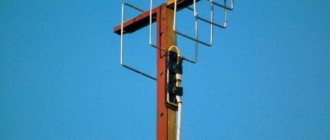
In summer cottages, a television signal can rarely be received without amplification: it is too far from the repeater, the terrain is usually non-uniform, and trees get in the way. For normal “picture” quality, antennas are needed. Anyone who knows at least a little how to handle a soldering iron can make an antenna for their dacha with their own hands. Outside the city, aesthetics are not given so much importance; the main thing is quality of reception, simple design, low cost and reliability. You can experiment and do it yourself.
Device characteristics
A television antenna is a bipolar device capable of emitting and receiving signals in the meter and decimeter ranges. Modern digital television requires accurate calculation of wavelength indicators, since only in this case is it possible to obtain a high-quality signal.
An analog antenna will pick up any wave, even the weakest one, while a digital one will require a clear, stable signal.
Modern TVs are capable of monitoring the level of digital signals themselves. For other devices you will need to calculate everything yourself.
Currently, television can operate at any frequency and on waves of different lengths. In order for a digital antenna created by yourself to function efficiently, it is necessary to adjust its waves in accordance with the transmitting station.
To do this you will need:
- Calculate the wavelength for each package of television channels;
- Determine the maximum wavelength that has the shape of a sine wave;
- Calculate half the length of the wave cross section.
The calculation is made using the formula: L = 300 / F. Where L denotes the length and F the frequency.
Options for homemade designs: general principles
Depending on the distance between your TV receiver and the transmitting antenna of the television center, the signal level will change. Another negative factor affecting the quality of television wave propagation is the presence of obstacles. Ideal reception occurs when there is a direct line of sight between the two antennas. That is, you can see the mast of the television center, even through binoculars. If there are buildings or tall trees in the path of the TV signal, there will be no reliable reception. However, waves reflected from other objects can be received by a TV antenna amplifier. If even weak waves do not “break through” to your house, you will have to make a mast. The network of television and radio broadcasting stations is located in such a way that you can receive a signal in any locality.
- Indoor antenna. Operates without an amplifier in relative proximity to the transmitting mast. If you can see the television center from your window, some of the channels can be caught literally with a piece of wire. How to make a television antenna with your own hands can be seen in the illustration.
The quality of workmanship in such conditions affects only the aesthetic component. But if you live on the 1st–3rd floor, and even surrounded by concrete boxes of a residential neighborhood, a simple design will not work. An indoor antenna, especially one made by yourself, will require a signal amplifier.Information: Indoor version, these are not necessarily the classic “horns” installed on top of the TV receiver. The product can be located on the wall, in a window opening, inside a glazed loggia.
The advantage of this design is that there is no need for weather protection.
- Street TV the antenna may look exactly the same as an indoor one. In this case, a prerequisite is high strength (so that the wind does not change the geometry) and protection of the contact group from corrosion. It is usually placed in close proximity to the window (in high-rise buildings) or on the roof of a private household. The connecting cable is relatively short, so an amplifier is not required to reliably receive a digital or analog signal. Except when the transmitting center is far away.
The structure is accessible for maintenance and repair; this is an undeniable advantage of being located nearby. - Outdoor antenna for long-range TV . As a rule, this is a rather bulky design with a screen and additional elements that amplify a weak signal. An electronic amplifier is welcome, but with proper design it may not be needed. Perhaps to compensate for a long cable (there will definitely be losses in it). Such devices are mounted on the roofs of high-rise buildings or on masts in private households. The fastening must be strong, otherwise the wind can easily destroy the structure.
- The antenna type is selected based on the reception characteristics and wind load in the region. For example, the Kharchenko antenna (the most popular homemade option) should not have a high windage. It may be necessary to choose another, more complex project.
Next, let's look at examples of making antennas at home using scrap materials, from simple to complex.
Selecting a location and connecting
Determining where to install the antenna usually depends on how it is connected. Placement can be indoor or outdoor. It should be understood that the external option involves more convenient signal reception.
- An outdoor antenna is usually mounted on the roof so that there are fewer obstacles in the form of walls and other buildings.
- But we must not forget that the clarity of the signal largely depends on the length of the cable. The larger it is, the lower the quality of transmission.
- An indoor antenna works best if there is a clear signal. Owners of dachas and country houses are looking for compromise options.
Experts recommend measuring signal quality with special instruments that can help eliminate errors in equipment placement.
Coaxial cable device
The simplest option for a self-made antenna is considered to be a product made from coaxial cable. Equipment can be manufactured quite quickly and without special training.
This antenna receives channels in the UHF range. In addition to the cable, to assemble the product you will need a piece of plywood or other sheet material to create a platform on which the device will be mounted.
You will also need cutting tools and electrical tape. Next you need to follow the instructions:
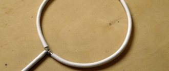
- Cut a piece of cable a little more than half a meter long and bend it into a ring without connecting the ends. Secure it like this to the base.
- Use another piece of cable (0.175 m) as a loop and connect.
- At the other end of the cable, install a connector for connecting to the TV.
The antenna is ready to receive the signal, but may be too weak. In this case, you will need to purchase an amplifier unit. You can also complicate the product by wrapping the cable in a figure eight.
A simple Wi-Fi antenna made from a metal can
An antenna for receiving a Wi-Fi signal can also be made from improvised means - from a tin can. This DIY TV antenna can be assembled in half an hour. This is if you do everything slowly. The jar should be made of metal, with smooth walls. Tall and narrow canning jars work great. If you will be installing a homemade antenna on the street, find a jar with a plastic lid (as in the photo). The cable is an antenna, coaxial, with a resistance of 75 Ohms.
This is what a Wi-Fi can antenna looks like from the outside
In addition to the can and cable, you will also need:
- RF-N connector;
- a piece of copper or brass wire with a diameter of 2 mm and a length of 40 mm;
- cable with a socket suitable for a Wi-Fi card or adapter.
Wi-Fi transmitters operate at a frequency of 2.4 GHz with a wavelength of 124 mm. So, it is advisable to choose a jar such that its height is at least 3/4 of the wavelength. For this case, it is better that it be more than 93 mm. The diameter of the can should be as close as possible to half the wavelength - 62 mm for a given channel. There may be some deviations, but the closer to the ideal, the better.
Dimensions and assembly
When assembling, a hole is made in the jar. It must be placed strictly at the desired point. Then the signal will be amplified several times. It depends on the diameter of the selected jar. All parameters are shown in the table. You measure the exact diameter of your can, find the right stitch, and have all the right dimensions.
How to make a Wi-Fi antenna with your own hands
| D - diameter | Lower limit of attenuation | Upper limit of attenuation | Lg | 1/4 Lg | 3/4 Lg |
| 73 mm | 2407.236 | 3144.522 | 752.281 | 188.070 | 564.211 |
| 74 mm | 2374.706 | 3102.028 | 534.688 | 133.672 | 401.016 |
| 75 mm | 2343.043 | 3060.668 | 440.231 | 110.057 | 330.173 |
| 76 mm | 2312.214 | 3020.396 | 384.708 | 96.177 | 288.531 |
| 77 mm | 2282.185 | 2981.170 | 347.276 | 86.819 | 260.457 |
| 78 mm | 2252.926 | 2942.950 | 319.958 | 79.989 | 239.968 |
| 79 mm | 2224.408 | 2905.697 | 298.955 | 74.738 | 224.216 |
| 80 mm | 2196.603 | 2869.376 | 282.204 | 070.551 | 211.653 |
| 81 mm | 2169.485 | 2833.952 | 268.471 | 67.117 | 201.353 |
| 82 mm | 2143.027 | 2799.391 | 256.972 | 64.243 | 192.729 |
| 83 mm | 2117.208 | 2765.664 | 247.178 | 61.794 | 185.383 |
| 84 mm | 2092.003 | 2732.739 | 238.719 | 59.679 | 179.039 |
| 85 mm | 2067.391 | 2700.589 | 231.329 | 57.832 | 173.497 |
| 86 mm | 2043.352 | 2669.187 | 224.810 | 56.202 | 168.607 |
| 87 mm | 2019.865 | 2638.507 | 219.010 | 54.752 | 164.258 |
| 88 mm | 1996.912 | 2608.524 | 213.813 | 53.453 | 160.360 |
| 89 mm | 1974.475 | 2579.214 | 209.126 | 52.281 | 156.845 |
| 90 mm | 1952.536 | 2550.556 | 204.876 | 51.219 | 153.657 |
| 91 mm | 1931.080 | 2522.528 | 201.002 | 50.250 | 150.751 |
| 92 mm | 1910.090 | 2495.110 | 197.456 | 49.364 | 148.092 |
| 93 mm | 1889.551 | 2468.280 | 194.196 | 48.549 | 145.647 |
| 94 mm | 1869.449 | 2442.022 | 191.188 | 47.797 | 143.391 |
| 95 mm | 1849.771 | 2416.317 | 188.405 | 47.101 | 141.304 |
| 96 mm | 1830.502 | 2391.147 | 185.821 | 46.455 | 139.365 |
| 97 mm | 1811.631 | 2366.496 | 183.415 | 45.853 | 137.561 |
| 98 mm | 1793.145 | 2342.348 | 181.169 | 45.292 | 135.877 |
| 99 mm | 1775.033 | 2318.688 | 179.068 | 44.767 | 134.301 |
The procedure is as follows:
- Cut off the top of the jar, wash thoroughly and dry.
- On the sidewall we mark the point where the emitter should be installed. She needs to be capped. We take something with a sharp tip (a large diameter drill will do, for example), place it exactly at this point, and hit the drill. It should not be strong so that the jar does not dent. But not too weak - there should be a trace.
Stages of manufacturing a Wi-Fi antenna
- You will need a set of drills - you need to start drilling with a small size, gradually increasing to 12-16 mm - according to the size of the purchased RF connector.
- We process the edges with a file or sandpaper.
- A copper or brass wire of a given length - 30.5 mm - must be soldered to the RF connector.
For normal soldering quality, sand the end of the wire until clean metal appears (without an oxide film). It is more convenient to solder by holding the connector in a vice with the lead positioned vertically upward. We heat the treated end of the wire with a soldering iron and solder it to the output of the RF connector. It is necessary to ensure that the emitter is strictly vertical. It looks like this when finished - We install the connector in the prepared place in the jar and tighten it with a clamping bolt.
- We solder the cable to the back side of the connector.
- DIY Wi-Fi antenna is ready.
You can do without an RF connector, but with it everything is much simpler - it’s easier to position the emitter vertically upward, connect the cable going to the router or Wi-Fi card.
Figure 8 antenna
Another version of the simplest device for receiving a television signal is a figure-of-eight antenna. The photos of the antenna presented give an idea of why this name was chosen.
The available materials are: a thick cardboard box, a special cable, a tip for connecting to a TV, a soldering iron, electrical tape, foil, glue, cutting tools.
The manufacturing process consists of several stages:
- Cover the bottom of the box with foil so that it serves as a signal reflector.
- Close the box and attach a figure-of-eight cable to the lid.
- From the middle part of the figure eight, bring out two ends to connect the product.
- Connect one end of the conductive cable to the TV using a connector, and run the other from the screen to the central core.
- Connect the ends of the cable to the exposed ends of the figure eight.
The figure-eight antenna is ready for use. It can provide a high-quality digital signal that is not inferior to satellite.
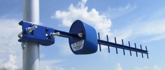
And finally, the most complex antenna for digital TV that you can make yourself
The log-periodic circuit allows you to get maximum gain without additional circuits.
The principle of operation of the design: in the direction of the signal source there are two conductive busbars, on which perpendicular vibrators are installed in strict sequence. Their length and distance between each other are calculated according to a strict algorithm. An error of 2–5% will lead to complete system inoperability. But a properly assembled antenna will receive analog and digital signals with the highest quality.
Note:
This type of antenna requires careful orientation towards the TV tower.
Can be used with a screen that helps strengthen a weak signal.
Device made from aluminum cans
A fairly popular antenna model is made from simple aluminum drink cans. The containers have a lot of advantages, as they have a sufficient area when unfolded, have good conductivity close to copper, and have a streamlined shape that reduces windage. The main advantage is the absolute availability of the material.
In addition to the aluminum parts, you will need 10 m of high-quality television cable with a durable central core and a continuous double braid. You also need to prepare a wooden hanger, fasteners, electrical tape and a soldering tool. Then, following the instructions, you can begin assembly:
- First, the cable is prepared. It is cut at one end and partially cleared of the insulating coating.
- The inner copper core is then released.
- The opposite end is equipped with a nozzle for connecting to TV.
- The contacts, freed from insulation, are soldered to the banks.
- The cans are fixed in one line on the hanger using electrical tape at a distance of 7.5 cm.
It is better to place an antenna made from cans on a window. It will work especially well if there are no high-rise buildings between it and the station.
Making your own television equipment is a great way to save money and an opportunity to acquire the necessary equipment. You can make your own Wi-Fi antenna, designs for analogue or digital television.
Instructions for assembling the best antennas
You can assemble many interesting and effective antennas with your own hands. Let's look at detailed instructions for making the best and easiest to make models.
Homemade #1 - simple TV antenna
If the repeater is located within 30 km from the dacha, then the most common design, assembled from two tubes and a cable, will do. The wire is connected to the corresponding TV input jack.
Layout and selection of materials
A typical device for a primitive country antenna is shown in the figure below. It can be seen that two tubes of the same length are joined on a plate, which in turn is fixed to the mast.
A pipe signal catcher can be made in a couple of hours. The work does not require any qualifications of the performer or the presence of expensive tools
The first thing you need to do is find out the broadcast frequency of the local TV tower - the length of the pipes depends on the parameter.
Broadcast band range – 50-230 MHz. Each channel requires its own length of antenna “whiskers”.
The table shows the design parameters of the signal catcher based on the frequency of the broadcasts. The broadcast band is divided into 12 channels
Pipes made of duralumin, steel, and brass are suitable for making an antenna. Their diameter can vary between 8-24 mm, most often they take 16 mm. The main condition is that the sections must be equivalent, prepared from pipes with the same properties.
Necessary materials:
- metal pipe - a cut 6 cm shorter than the length determined from the table values;
- wire with a resistance of 75 Ohms , the required length is the distance from the TV to the antenna plus 2 m for sagging and matching loop;
- thick electrical insulating getinax - thickness from 4 mm;
- metal strips , clamps for fixing pipes on a plate;
- mast for the antenna - this can be a corner; if the height is small, it is permissible to use a wooden block.
For work, it is advisable to stock up on a soldering iron, solder, and flux. It is recommended to solder the connections of the central conductors - this will extend the life of the device and improve image quality.
To protect against oxidation, the joint areas must be filled with silicone or epoxy resin. An affordable, but not reliable way is to wrap it with electrical tape.
Assembly and configuration of the invention
First, cut the required size of the pipe and saw it into two equal parts. You can use metal cutters.
The next step is to flatten the tubes on one side for easy attachment to the holder. The pieces are applied to the getinax and fixation points are marked.
The distance between the inner ends of the tubes is 6 cm, between the outer ends - the distance indicated in the table.
Subsequent work progress:
- Secure the antenna whiskers to the holder with clamps, and fix the getinax plate itself on the mast.
- Connect the pipes through a matching device - cable loop type RK-1,3,4. The element parameters are displayed in the right column of the table, the manufacturing principle is shown in the antenna design diagram.
- Solder the central cores to the ends of the tubes, connect the braid with a piece of a similar conductor.
- Connect the central conductors of the ends of the matching loop to the television cable. Connect the braid with copper wire.
- Fix the loop and the downward wire on the rod.
- Raise the mast to the roof of the country house and adjust the antenna.
Two people are needed to determine the optimal position of the device. The first rotates the antenna on the street, and the second monitors the change in the image on TV.
To quickly set up, you can check with your neighbors on which side of the house the receiver is located and where the vibrators are directed
Having detected good signal quality, the structure is fixed in the selected position.
Homemade #2 - loop antenna made from pipe
The module is a little more difficult to create, but it expands the reception radius to 40 km. The main difficulty lies in the need to bend the pipe.
The bending radius does not have a special role. The main requirements for the device: the distance between the inner ends is 65-70 mm, the evenness and symmetry of the arrangement of the wings
The length of the cable and pipe is calculated based on the broadcast frequency of TV channels.
Blanks are made to suit the required parameter - the vibrator and the wire for the matching device are measured and cut. The recommended pipe diameter is 12-18 mm.
Table values for the correspondence between channel frequency and signal catcher parameters. For example, with an airwave indicator of 93.25 MHz, the length of the pipe should be 151 cm, and the length of the matching cable should be 104 cm
Assembly begins by bending the pipe. The edge of the vibrator is flattened and sealed. The pipe is filled with sand, and the second end is sealed in the same way as the first. The edges can be sealed by placing the plugs on silicone.
The shaped pipe is attached to the mast. Matching loops are screwed and soldered to the ends of the vibrator, and the television cable is fixed. Secure the braid with copper wire and begin setting up.
Homemade #3 - Kharchenko signal catcher
The figure-of-eight or zigzag television antenna is suitable for DVB-T2 digital television, broadcasting in the UHF range. The module is easy to manufacture. To implement the project, you will need conductive metal.
Calculation and drawing development
The design of the TV antenna is very primitive - two squares/diamonds fastened together. In the original design, the Kharchenko module provides for a reflector located behind the figured elements.
A field of metal strips is required for analog signals. Digital television reception is possible without a reflector. The field can be developed later if the reception is poor
To make a zigzag antenna, it is not necessary to calculate the wavelength. It is advisable to build a structure with more broadband - this will increase its capabilities.
If desired, you can calculate the device parameters. Divide the wave value of the transmitted signal by 4 - the resulting value is the side of the square.
There should be a small distance between the two parts of the TV antenna. To maintain the gap, it is enough to make the outer sides longer and the inner sides shorter. Length of sides (B1 and B2) - at your discretion
The example shown shows a drawing of an antenna with side parameters: B1 - 14 cm, B2 - 13 cm. The difference in lengths of one centimeter gives the required distance between the squares.
The lower sections are extended by 1 cm. This gap is necessary for the loop for soldering the antenna cable.
Frame making and cable preparation
Subsequent calculations will be given in relation to the data in the drawing shown above. The total perimeter of the squares is 112 cm. You should cut the wire to the required length and form the part according to the diagram.
Work order:
- Bend the wire in the middle at a right angle.
- Next come two sections of 14 cm each, followed by sides of 13 cm each. After each bend, we check the evenness of the corners, it must be strictly 90 degrees.
- When the first square is formed, begin to create the second figure. Again there are versatile elements of 14 cm each, and behind them are two parts of 13 cm + 1 cm.
Minor differences in side lengths are acceptable. The main thing is to maintain right angles.
If the molding of the structure is done correctly, then between the two parts of the TV antenna there should be a distance of 1.5-2 cm
The next step is preparing the cable. It is cleaned on both sides. An incision is made along the circumference of the cable, 2-2.5 cm from the edge.
The work is done carefully so as not to damage the inner braid. Along the cut line, the cable is slightly broken and the insulation is removed.
The braid and foil must be twisted into a bundle. You should get two conductors: a central monocore and a twist. Both elements must be tinned. The wire should stick out 2 cm, cut off the excess
Solder the plug on the other side of the cable. The wire must be cleaned to 1 cm, the conductors must be formed and tinned.
In areas where soldering is performed, clean the plug with sandpaper and wipe with alcohol. Solder a monocore to the central output, and a twist to the side output. Crimp the grip around the insulation, screw on the plastic tip, or alternatively, fill it with non-conductive sealant. Before the composition dries, assemble the plug.
The order of connecting elements
The final stage of assembly is the joining of the frame and cable. If there is no connection to a specific channel, then it is better to do the soldering at the midpoint to expand signal capture.
The cut end of the cable is connected to the two sides of the square in the center. Before final fixation, you can check the performance of the antenna. If everything is normal, then seal the soldering area.
The most reliable method is to fill it with silicone or glue. A plastic lid from a five-liter eggplant is suitable for the case.
Holes are made in the mini-container for the square elements, a frame with a wire is placed and filled with a sealing compound.
Homemade product #4 – “double square” antenna
The narrowband design will solve the problem of a weak signal or clogging of the broadcast with a stronger broadcast. The antenna is also suitable for receiving digital television. The main condition for operation is a clear orientation towards the signal distributor.
Device diagram and dimensions
Structurally, the TV antenna is presented in the form of two frames connected at the top and bottom by arrows. The large square is a reflector, the smaller one is a vibrator.
A variation with three frames is possible, providing a high signal gain. Least square – director
The upper boom is made of metal, and the lower one is made of getinax, textolite or other insulating material.
Requirements for the TV antenna device:
- the centers of the squares must be on the same line, this straight line faces the transmitter;
- the smaller frame has an open contour, the ends are fixed to the textolite plate;
- The upper part of the mast for the antennas is made of wood.
The parameters for the manufacture of two-element frame television antennas are taken from the table. The dimensions of the working elements depend on the type of waves: decimeter or meter.
Explanations for the table: B – side length of the smaller square, P – value of the larger frame, A – distance between two elements, W – loop in a short-circuited bridge
In a three-frame design, the distance between the ends of the middle frame is increased to 5 cm.
Assembly and connection
To connect the frame to the antenna cable, you will need a balun short-circuited cable. The device is constructed from sections of antenna wire.
The right element is a cable, the shortened left one is a feeder. A television cable is attached to the place where they are connected. The length of the segments is determined from the table, taking into account the wavelength of the signal.
Before assembling the elements, they are cleaned. The aluminum layer is removed from the cable and the braid is twisted into a bundle. The central conductor is cut off
The same actions are performed with the feeder, leaving the cable core.
Further sequence of work:
- Solder the central core of the feeder and the cable braid to the left end of the vibrator.
- Attach the feeder twist to the right end of the active frame.
- Connect the bottom of the cable to the feeder braid with a metal jumper. Solder the harnesses with low-melting solder.
- The cable sections must run parallel, the distance is 5 cm. To fix the distance, dielectric material is used. The matching device is mounted on a textolite plate.
- Solder the television cable to the bottom of the feeder, joining the corresponding elements - braid to braid, rod to rod.
The use of a matching device reduces the likelihood of interference and eliminates the double image effect. You cannot do without it if you are at a significant distance from the transmitter.
Homemade #5 - TV antenna made from tin cans
The original design of the antenna using improvised means significantly improves the signal quality. This option is suitable for a dacha in the suburbs, not far from a TV tower.
To create a primitive device you will need: 2 beer cans of 0.5 or 0.75 liters, self-tapping screws, a 3-5 m television cable, a screwdriver, a soldering iron, tin, a wooden pin or hanger, and electrical tape.
Subsequent actions can be divided into several stages.
Preparing the cable and making contacts
When preparing the cable, clean the insulation by retreating 10 cm. Divide the cable into two conductors - the central core and the braided twist. At the other end of the cable you need to install a regular plug.
When making contacts, the twisted cable screen is fastened to one can, and the copper core to the other. Self-tapping screws are suitable for fixing.
To obtain a better image, it is better to strengthen the fastenings by soldering. Connections must be sealed
Assembling a homemade structure
During assembly, it is necessary to make a supporting structure for the signal receiver. In the simplest version, you can use ordinary coat hangers. A wooden stick will also work.
The cans are fixed to the mast with adhesive tape or electrical tape, the structure is lifted onto the roof and the setup begins, selecting the optimal location for the improvised antenna.
When working, you must use containers with a smooth surface; ribbed materials are not suitable. The jars are pre-washed and dried.