I had already created several static electricity generators before and these projects always aroused great interest. They are a lot of fun to play with and allow you to do a lot of different tricks with ESD. For example, you can shock your friends (and yourself), force sand or dust particles with your hands to behave strangely, since they are susceptible to static charges. You can also attract a stream of water, charge paper so that it sticks to the wall, and perform many other magical tricks.
The video above demonstrates the assembly process for this project, and the text version below will give you step-by-step instructions. This is the third version of my static electricity generator, and it is the cheapest. It allows you to create a charge about the same as what happens when you catch a spark from a carpet while walking on it in your pajamas.
The USB ionizer, which is the main component of the project, can be found here: link
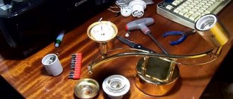
We will need:
- Ionizer.
- Insulated wire.
- Heat-shrink tubing.
- Hot glue.
- Solder and soldering iron.
- Button batteries 1.5v.
- Insulating tape.
Instructions for assembling a static electricity generator with your own hands
I had already created several static electricity generators before and these projects always aroused great interest. They are a lot of fun to play with and allow you to do a lot of different tricks with ESD. For example, you can shock your friends (and yourself), force sand or dust particles with your hands to behave strangely, since they are susceptible to static charges. You can also attract a stream of water, charge paper so that it sticks to the wall, and perform many other magical tricks.
The video above demonstrates the assembly process for this project, and the text version below will give you step-by-step instructions. This is the third version of my static electricity generator, and it is the cheapest. It allows you to create a charge about the same as what happens when you catch a spark from a carpet while walking on it in your pajamas.
The USB ionizer, which is the main component of the project, can be found here: link
- Ionizer.
- Insulated wire.
- Heat-shrink tubing.
- Hot glue.
- Solder and soldering iron.
- Button batteries 1.5v.
- Insulating tape.
Technology - youth 1964-03, page 20
I met Vasily Lavrovsky in Omsk. The conversation began with the most general topics, and then he suddenly asked:
— Have you ever seen electric generators that do not have a single meter of wire, but can produce a current of hundreds of thousands of kilowatts? Do you think it's impossible? So now I’ll tell you about an electric generator that can be built without copper, insulating materials, with an insignificant amount of electrical steel, without step-up transformers for transmitting current over long distances.
And I heard a story similar to a fantasy story...
LONG FORGOTTEN
Electricity was first produced by friction. Electrostatic machines were built on this principle. And then these machines almost ceased to be used - only some varieties of them are used in nuclear physics, electronics and other fields. The fact is that although they produce a very high voltage current, the current strength is negligible.
What if these high-voltage machines were given more power? After all, then you will get a generator with unlimited possibilities...
But how? To many, such a task seemed almost impossible to solve. However, scientists did not lose hope. “It seems to me absolutely possible,” wrote academician A.F. Ioffe more than twenty years ago, “electrostatic generators of thousands and tens of thousands of kilowatts...”
Meanwhile, until now, electric current has continued and continues to be obtained using complex, expensive generators that operate on the principle of electromagnetic induction. ,
GENERATOR FROM CONDENSER
Oppositely charged capacitor plates attract each other. To move them apart, you will need to expend mechanical force, which must exceed the force of electrical interaction. The expended mechanical energy will be spent on increasing the potential difference on the capacitor plates. The capacitance of the capacitor will decrease, and the voltage on its plates will increase.
This principle served as the basis for the creation of Lavrovsky’s capacitive generators.
If we make a model in which one capacitor plate remains stationary, and the second rotates clockwise, and we attach an exciter to the collector and stationary plates, then...
Look at the picture. You can verify that when removing plate “a” from plate “g” and reducing the capacity from Cmax to Cmin. the tension will increase as many times as Smack. RELATES TO Smnn. So, if the pathogen gives 1 000 in,
and the ratio of capacitances is 50, then the generator will deliver 50 thousand volts to the load.
But... such machines will only be good in space, because for their successful operation they need an absolute vacuum. On the ground, the low dielectric constant of air interferes. A discharge occurs between the plates or rings, and the accumulated charges disappear.
In a vacuum, the breakdown voltage reaches 100 million V per 1 cm of distance between the plates. Under these conditions, due to high voltage, large charges can be obtained and retained.
To move the capacitor plates apart. you have to use force.
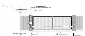
GENERATOR VASILY
Vladimir STRELKOV, our specialist. Correspondent Fig. I. KALEDINA
In terrestrial conditions, Lavrovsky proposed using a material with a high dielectric constant - barium titanate.
...But again the air interfered, this time because of another peculiarity. The most insignificant layer of air between the rotor and stator made of barium titanate negated the wonderful properties of ceramics: on the one hand, to have an ultra-high dielectric constant, high polarization of the medium, and on the other, to be a good insulator. The air was almost not polarized, and the generator worked with negligible efficiency. And yet Lavrovsky found a way out.
TO THE RESCUE OF PEACEFUL ATOM...
Ionized gas is an excellent medium for polarization!
If the air in the rotor-stator gap is ionized, it acquires a high dielectric constant, sufficient for good operation of the machine.
To do this, it is necessary to cover sections of the rotor and stator with a radioactive isotope with alpha decay. Then the required polarization will appear in the gap. Particles with alpha decay will eliminate the need for complex and expensive protection.
As the air becomes rarefied, the amount of ionizing isotope that must be applied in the gap will decrease. And in order to reduce the amount of radioactive substances to the limit and at the same time increase their efficiency, you can use a “rough vacuum” in the gap - 5-10 mm of mercury.
…PLUS PLASTIC
But barium titanate is ceramic. Its strength is significantly less than steel. A barium titanate rotor cannot be given a large number of revolutions - it will shatter into pieces.
vacuum 5″l(lft.
PATIENT
•METAAAA.COATED AND 30-STRONG LINKS WITH RAASHIKSHY SHOP NZ PLASTICS
And for generators that are installed at power plants, speeds of up to 3 thousand rpm are required.
PATIENT
BARIUM TITANATE
LOAD
In this way, the simplest model of a capacitive generator for operation in space can be built.
LOAD
Ceramics came to the rescue.
It turned out that you don’t have to rotate heavy ceramics. The “former” ceramic rotor is made motionless. A metal n-wheel with plastic insulating inserts is placed between it and the stator. When the insert is against isolated clouds during movement,
16
Features of PCB tracing when organizing ESD protection
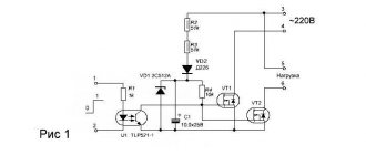
When designing a PCB, it is very important to comply with ESD protection regulations. Figure 17 shows a classic static electricity protection circuit.
Rice. 17. Classic protection against static electricity
In this circuit, the protection device (diode) is located between the external connector and the device we want to protect. Please note that when a static discharge event occurs, the impedance of the PCB interconnect wires becomes important. High currents and conductor impedance can result in unwanted overvoltage at the terminal of the protected device. The inductance of the conductors varies depending on the manufacturing technology of the printed circuit board, but approximately it can be assumed that the inductance of 1 mm of conductor is equal to 1 nH. The issue of conductor inductance is especially important for the areas highlighted in red in Figure 17. Assume that the inductance of one conductor is 5 nH. An equivalent circuit with such assumptions is shown in Figure 18.
Rice. 18. Electrostatic discharge event model
When an ESD event occurs, the diode is expected to limit the voltage at the input of the protected device to the clamping voltage, thereby providing overvoltage protection. However, for the circuit shown in Figure 18, this is not entirely true because ESD generates a significant current that also flows through the circuit board conductors. As a result, a voltage drop is formed across the inductances of the printed conductors, proportional to the magnitude of the inductance and the rate of change of current. In this case, the input of the protected device will have a voltage equal to the sum of the voltage drops across the inductors and the diode. If we assume that the conductor inductance is 5 nH and the current rate of change is 37.5 A/ns, then the total voltage drop can exceed hundreds of volts. Such voltage is quite capable of damaging the microcircuit.
The solution to this problem is very simple - you need to control the shape of the PCB conductors. An example of the shape of the conductors is shown in Figure 19.
Rice. 19. Conductor shape for ESD protection
The length of the conductors should be minimized, and the shape should be similar to that shown in Figure 19. The length of the grounding conductor should also be minimized, and most importantly, to minimize parasitic inductance, the interlayer junction should be located as close as possible to the protection device and to the ground terminal of the protected device.
An equivalent circuit for proper protection is shown in Figure 20.
Rice. 20. Equivalent circuit for proper ESD protection
In the case of the circuit presented in Figure 20, the voltage on the protected device will not exceed the clamping voltage of the diode. It is also recommended that the protection device be located as close as possible to the source of the disturbance, in this case the connector.
Original story
Testatika's electrostatic generator, based on the 1989 Pidgeon, includes an inductor circuit. The "free energy" device is supposed to use the energy potential of the atmosphere, which is in some respects reminiscent of the Wimshurst unit. It was built by an engineer and promoted by the Swiss religious community.
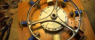
Inventor Bauman claimed that the concepts for the devices came to him through visitors from outer space while he was in a Swiss prison in the 1970s on charges of child abuse associated with a religious cult of which he was the founder. Testatika is known as the Swiss ML converter or Thesta-Distatica. Approximate diagram of the Testatika generator:
Working devices are said to have existed since the 1960s in a religious group called Methernitha (near Bern, Switzerland). The specific and exact operating principles of the devices are unknown. According to various sources, Testatika uses the design features of the Pidgeon electrostatic machine: it has an inductive circuit, a capacitive circuit and a thermionic rectifier valve. Until now, the devices have not used semiconductors or transistors. The entire device can be divided into two large components: a generator and auxiliary circuits.
Generator
The basic Pidgeon system specifies modifications to increase, stabilize, and lock charge polarities at specific points on the machine. The Wommelsdorf multi-disc condenser machine also has aspects applicable to the Testatika. Testatika has 50 steel gratings per disc. This is an innovation for the electrostatic machines of the past. Based on the speculative conclusions of enthusiastic scientists who studied the invention, several distinctive features of Mr. Bauman’s brainchild can be identified:
- The principle is based on previous research and patents on electrical circuits in which the sectors are corrugated.
- Such corrugated electrostatic sectors are more efficient charge carriers compared to their flat counterparts.
- The disks transfer charges from the rotating elements to the collectors.
- Perforated keypads replace the standard brushes or pointed guides of previous electrostatic machine designs.
- The collectors do not touch the disks; the charge passes through a parallel air gap from the metal grids to the pads. During operation, the air gap is exposed to miniature eddy currents that circulate around the perforated surface.
The above process, unlike the Pidgeon system, has an additional indirectly connected manifold on the front top center of the first disk.
The discs rotate at a speed of only 60 rpm (variable up to 15 rpm). Located very close to each other. The front one is transparent, made of plexiglass (positively charged “cloudy”), the back one is a dark disk (negative “grounded”) correspond to the triboelectric series. The disks can be doped with paramagnetic particles.
Neutralizing rods are placed so that charges are induced from one area, accumulating in other places. They align and stabilize particles of opposite signs, ensuring the correct distributed charge polarity in certain areas.
Auxiliary circuits
The Testatika electrostatic generator converts static energy into electromotive force using its oscillatory circuit and valve rectifiers. Electric current fluctuations are controlled by the connection of the thermionic rectifier valve, cylinder capacitors and natural resistance.
The oscillations of the electromagnetic circuit are modulated through transformers, rectified into DC pulses. German Plazon, an Estonian inventor, describes such methods for converting static energy. The thermionic rectifier valve has an anode mesh plate, a spiral copper grid, a glowing (heated) cathode wire running horizontally through its center, and associated wires.
The horseshoe magnet contains four blocks of plexiglass medium alternating with copper and aluminum plates. Two horseshoe-shaped magnets with laminated blocks of metallized plexiglass, alternating with copper and aluminum plates, form, as various sources say, “electronic cascade generators.” There is a chain reaction that produces “free electrons.” Insulated wire is also wound around horseshoe magnets for induction purposes.
Two outer cylinders are used. The connection of each individual secondary winding may be based on the "bursting discharge coil" developed by Nikola Tesla. The cylinders on the sides act partly as capacitors. This configuration forms a network of pulses. Each cylinder has a core of 6 anisotropic ferrite magnets with a hollow ring, plastic spacers for air gaps that form the transformer.
The central input rod connects at the bottom to a stack of interconnected pancake coils. One transformer is connected to the output negative polarity and the other to the output positive polarity with respect to the reluctance gaps. Each is connected to the secondary winding of the pancake coil. The use of aluminum shielding mesh and solid copper shielding sheets is aimed at minimizing stray electrostatic charges.
The two throttle assemblies are housed in vertical double glass tubes with a helically oriented aluminum strip. The pipes make up two-thirds of the tower's height. The glass tube ends at the top with rectangular brass rods that connect to the rectifier. The wooden base has alternating layers of perforated metal insulating plates forming a storage capacitor.
Perhaps this is yet another example of the alternative thinking needed to transform the current energy and environmental crisis. Despite the creation and demonstration of this device, the technology was not used by the rest of the world for more than 30 years, not only for moral reasons (the invention was the brainchild of a sect, and the engineer himself was accused of child abuse), but because no eyewitnesses There is no exact technical data about the structure of the miracle machine.
But the simple fact that the Methernitha religious community itself does not use the device casts doubt on its effectiveness in generating free energy. All their electricity needs are met by a couple of wind turbines, and they buy electricity like everyone else. The big question about the capabilities of this machine still remains unanswered.
DIY electrostatic generator
The operating principle of a static electricity generator (also called electrophore machines) is that the disks rotate relative to each other in opposite directions and create positive and negative charges. When the disks rotate, as charges accumulate, a discharge occurs—lightning between the electrodes.