What is a thyristor and their types
Many have seen thyristors in the “Running Fire” garland; this is the simplest example of the device described and how it works. A silicon rectifier or thyristor is very similar to a transistor. This is a multilayer semiconductor device, the main material of which is silicon, most often in a plastic housing. Due to the fact that its operating principle is very similar to a rectifying diode (AC rectifier devices or dinistors), the designation on the diagrams is often the same - this is considered an analogue of a rectifier.
Photo - Running fire garland diagram
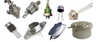
There are:
- ABB turn-off thyristors (GTO),
- standard SEMIKRON,
- powerful avalanche type TL-171,
- optocouplers (say, TO 142-12.5-600 or MTOTO 80 module),
- symmetrical TS-106-10,
- low frequency MTTs,
- triac BTA 16-600B or VT for washing machines,
- frequency TBC,
- foreign TPS 08,
- TYN 208.
But at the same time, IGBT or IGCT type transistors are used for high-voltage devices (furnaces, machine tools, and other industrial automation).
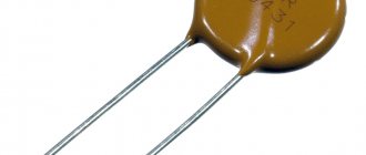
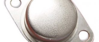
Photo – Thyristor
But, unlike a diode, which is a two-layer (PN) transistor (PNP, NPN), a thyristor consists of four layers (PNPN) and this semiconductor device contains three pn junctions. In this case, diode rectifiers become less efficient. This is well demonstrated by the thyristor control circuit, as well as any electricians’ reference book (for example, in the library you can read a book by the author Zamyatin for free).
A thyristor is a unidirectional AC converter, meaning it conducts current in one direction only, but unlike a diode, the device can be made to operate as an open circuit switch or as a DC rectifying diode. In other words, semiconductor thyristors can only operate in switching mode and cannot be used as amplification devices. The key on the thyristor is not capable of moving to the closed position on its own.
The silicon controlled rectifier is one of several power semiconductor devices, along with triacs, AC diodes, and unijunction transistors, that can switch from one mode to another very quickly. Such a thyristor is called high-speed. Of course, the class of the device plays a big role here.
DIRECTORY THYRISTORS
DIRECTORY THYRISTORS
A thyristor is a switching semiconductor device with two stable states having three or more pn junctions. Thyristors are intended for use in power converter circuits, pulse modulators, contactless control equipment, pulse amplifiers, generators, inverters and other switching circuits.
Type Uob.,p, Uob.,max,V Uos.,p, Uos.,max,V Ios.,i, A Ios.,av., Ios.,p.,A Uos.,i, Uos., V Uy.,not,V Izs.,p., Izs.,mAKU202A – 25* 30 10* <1.5* >0.2 <4*KU202B 25* 25* 30 10* <1.5* >0 ,2 <4*KU202V – 50* 30 10* <1.5* >0.2 <4*KU202G 50* 50* 30 10* <1.5* >0.2 <4*KU202D – 100* 30 10 * <1.5* >0.2 <4*KU202E 100* 100* 30 10* <1.5* >0.2 <4*KU202ZH – 200* 30 10* <1.5* >0.2 < 4*KU202I 200* 200* 30 10* <1.5* >0.2 <4*KU202K – 300* 30 10* <1.5* >0.2 <4*KU202L 300* 300* 30 10* < 1.5* >0.2 <4*KU202M – 400* 30 10* <1.5* >0.2 <4*KU202N 400* 400* 30 10* <1.5* >0.2 <4* KU208A 100* 100* 10 5* <2* – <5*KU208B 200* 200* 10 5* <2* – <5*KU208V 300* 300* 10 5* <2* – <5*KU208G 400* 400* 10 5* <2* – <5*
KN102A 10* 5 10 0.2 <1.5* 2 <0.08*KN102B 10* 7 10 0.2 <1.5* 3 <0.08*KN102V 10* 10 10 0.2 <1.5 * 4 <0.08*KN102G 10* 14 10 0.2 <1.5* 6 <0.08*KN102D 10* 20 10 0.2 <1.5* 8 <0.08*KN102Zh 10* 30 10 0.2 <1.5* 12 <0.08*KN102I 10* 50 10 0.2 <1.5* 15 <0.08*TS2-10 100-1100 100-1100 20 10 2 1.54 5TS2- 16 100-1100 100-1100 30 16 2 1.28 5TS2-25 100-1100 100-1100 50 25 2 1.12 5TS112-10 100-1200 100-1200 20 10 1.85 0.25 3TS112-16 100- 1200 100-1200 30 16 1.85 0.25 3Device type Urev.,p, Urev.,max,V Uss.,p, Uss.,max,V Ios.,i,A Ios.,avg., Ios. ,p.,A Uos.,i, Uos.,V Uu.,not,V Izs.,p., Izs.,mATS122-20 100-1200 100-1200 30 20 1.85 0.25 2TS122-25 100 -1200 100-1200 40 25 1.85 0.25 2TS132-40 100-1200 100-1200 60 40 1.85 0.25 5TS132-50 100-1200 100-1200 80 50 1.85 0.25 5TS142-6 3 100-1200 100-1200 150 63 1.8 0.25 7TS142-80 100-1200 100-1200 200 80 1.8 0.25 7TS161-100 200-1200 200-1200 150 100 1.45 0.3 1 5TS161- 125 200-1200 200-1200 200 125 1.45 0.3 15TS161-160 200-1200 200-1200 250 160 1.45 0.3 15TO142-50 600-1200 600-1200 78 50 1.85 0.9 5TO142 -63 600-1200 600-1200 98 63 1.75 0.9 5TO142-80 600-1200 600-1200 120 80 1.75 0.9 5T112-10 100-1200 100-1200 16 10 1.85 0.3 2.5Т112-16 100-1200 100-1200 25 16 1.8 0.3 3Т122-20 100-1200 100-1200 31 20 1.75 0.3 3Т122-25 100-1200 100-1200 39 25 1.75 0.3 3t222-20 100-1200 100-1200 31 20 1.75 0.3 3t222-25 100-1200 100-1200 39 25 1.75 0.3 3T131-40 100-1200 100-1200 63 40 1, 75 0.3 5Т131-50 100-1200 100-1200 75 50 1.75 0.3 6Т132-16 1300-2000 1300-2000 25 16 2.2 0.3 9Т132-25 1300-2000 1300-2000 39 25 2 ,2 0.3 9T232-16 1300-2000 1300-2000 25 16 2.2 0.3 9T232-25 1300-2000 1300-2000 39 25 2.2 0.3 9Type Uform.,p, Uform.,max, V Uss.,p, Uss.,max,B Ios.,i,A Ios.,av., Ios.,p.,A Uos.,i, Uos.,V Uy.,not,V Iss.,p ., Izs.,mAT141-40 1300-2000 1300-2000 63 40 1.95 0.3 15T141-50 1300-2000 1300-2000 78 50 2.1 0.3 15T142-32 1300-2000 1300-200 0 50 32 2.1 0.3 9T142-40 1300-2000 1300-2000 63 40 1.95 0.3 9T142-50 1300-2000 1300-2000 78 50 2.1 0.3 9T242-32 1300-2000 1300-2000 50 32 2.1 0.3 9T242-40 1300-2000 1300-2000 63 40 1.95 0.3 9T242-50 1300-2000 1300-2000 78 50 2.1 0.3 9T142-63 100-1200 100-120 0 99 63 1.65 0.3 6T142-80 100-1200 100-1200 125 80 1.65 0.3 6T242-63 100-1200 100-1200 99 63 1.65 0.3 6T242-80 100-1200 100- 1200 125 80 1.65 0.3 6Т151-63 1300-2000 1300-2000 99 63 1.95 0.3 20Т151-80 1300-2000 1300-2000 125 80 1.95 0.3 20Т161-125 3 00-1600 300 -1600 250 125 1.75 0.45 15T161-160 300-1600 300-1600 250 160 1.75 0.45 15T171-200 300-1600 300-1600 500 200 1.75 0.45 30T171 -250 300-1600 300-1600 500 250 1.75 0.45 30T171-320 300-1600 300-1600 500 320 1.6 0.45 30T123-200 400-1600 400-1600 530 200 1.9 0.45 15T1 23-250 400- 1200 400-1200 610 250 1.75 0.45 15T123-320 400-800 400-800 700 320 1.65 0.45 15T153-630 1300-2400 1300-2400 1500 630 2.1 0, 5 50T153-800 1000 -1800 1000-1800 1820 800 1.9 0.5 50T253-800 2000-2400 2000-2400 1850 800 2.1 0.5 50T353-800 2800-3200 2800-3200 1250 800 2.3 0.2 70T153-630 1300-2400 1300-2400 1500 630 2.1 0.5 50T153-800 1000-1800 1000-1800 1820 800 1.9 0.5 50T253-800 2000-2400 2000-2400 1850 80 0 2.1 0.5 50T353- 800 2800-3200 2800-3200 1250 800 2.3 0.2 70
A triac can conduct current in two directions, replacing two back-to-back SCRs. Triacs are made on the basis of a five-layer silicon structure and are intended for use in switching and control equipment.
TYPE Imax(A) Umax(V) Ioverload(A) IGT(gate current), mA(max) Q1 Q2 Q3 Q4 T2500D 6 25 60 MAC8N 35 – MAC9M – MAC9N 800 MAC228A8 600 5 5 5 10 MAC228A10 800 BTA08-600CW3G 50 – BTA08-800CW3G 800 BTB08-600CW3G 600 BTB08-800CW3G 800 BTA08-600BW3G – BTA08-800BW3G 800 BTB08-600BW3G 600 BTB08-800BW3G 80 0 MAC12SM 12 600 5 5 5 – MAC12SN 800 MAC12M 35 – MAC12N 800 MAC212A8 75 MAC212A10 800 BTA12-600CW3G 35 – BTA12-800CW3G 800 BTB12-600CW3G 600 BTB12-800CW3G 800 BTA12-600BW3G 50 – BTA12-800BW3G 800 BTB12-600BW3G 600 BTB12-800 BW3G 800 MAC15SM 15 600 5 5 5 – MAC15SN 800 MAC15M 35 – MAC15N 800 MAC15A6 75 MAC15A8 600 MAC15A10 800 MAC16M – MAC16N 800 MAC16CM 16 – MAC16CN 800 BTA16-600CW3G 35 – BTA16-600CW3G 800 BTB16-600CW3G 600 BTB16-800CW3G 800 BTA1 6-600BW3G – BTA16-800BW3G 800 BTB16-600BW3G 600 BTB16-800BW3G 800
- GUIDE TO IMPORTED DIODES
- PRECIOUS METALS IN RELAYS AND RESISTORS
Application of thyristor
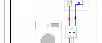
The purpose of thyristors can be very different, for example, a homemade welding inverter using thyristors, a charger for a car (thyristor in the power supply) and even a generator are very popular. Due to the fact that the device itself can pass both low-frequency and high-frequency loads, it can also be used for a transformer for welding machines (their bridge uses exactly these parts). To control the operation of the part in this case, a voltage regulator on the thyristor is needed.
Photo - using Thyristor instead of LATR
Don't forget about the ignition thyristor for motorcycles.
PART ONE GENERAL INFORMATION ABOUT THYRISTORS
Section one. Classification of thyristors 4.6. Classification and symbol systems 11 4.7. Graphic symbols 20 4.8. Terms, definitions and symbols of electrical parameters of thyristors 21 1.4- Standards for semiconductor devices-thyristors 33
Section two. Features of the use of thyristors in electronic equipment
4.9.General provisions 35 4.10.Main features of thyristors 40 4.11.Recommendations for the selection and use of thyristors 40
Description of design and principle of operation
The thyristor consists of three parts: “Anode”, “Cathode” and “Input”, consisting of three pn junctions that can switch between “ON” and “OFF” positions at very high speed. But at the same time, it can also be switched from the “ON” position for different durations, i.e., over several half-cycles, in order to deliver a certain amount of energy to the load. The operation of a thyristor can be better explained by assuming that it will consist of two transistors connected to each other, like a pair of complementary regenerative switches.
The simplest microcircuits demonstrate two transistors, which are combined in such a way that the collector current, after the “Start” command, flows into the NPN transistor TR 2 channels directly into the PNP transistor TR 1. At this time, the current from TR 1 flows into the channels into the bases of TR 2. These two interconnected transistors are arranged such that the base-emitter receives current from the collector-emitter of the other transistor. This requires parallel placement.
Photo - Thyristor KU221IM
Despite all safety measures, the thyristor may involuntarily move from one position to another. This occurs due to a sharp jump in current, temperature changes and other various factors. Therefore, before you buy a thyristor KU202N, T122 25, T 160, T 10 10, you need to not only check it with a tester (ring), but also familiarize yourself with the operating parameters.
Typical thyristor current-voltage characteristics
To start discussing this complex topic, look at the diagram of the current-voltage characteristics of a thyristor:
Photo - characteristics of the thyristor current-voltage characteristic
- The segment between 0 and (Vо,IL) fully corresponds to direct locking of the device;
- In the Vvo section, the thyristor is in the “ON” position;
- The segment between the zones (Vvo, IL) and (Vн,In) is the transition position in the on state of the thyristor. It is in this area that the so-called dinistor effect occurs;
- In turn, points (Vн,In) show on the graph the direct opening of the device;
- Points 0 and Vbr are the section where the thyristor is turned off;
- This is followed by the segment Vbr - it indicates the reverse breakdown mode.
Naturally, modern high-frequency radio components in a circuit can affect the current-voltage characteristics in an insignificant way (coolers, resistors, relays). Also, symmetrical photothyristors, SMD zener diodes, optothyristors, triode, optocouplers, optoelectronic and other modules may have different current-voltage characteristics.
Photo - current-voltage characteristic of a thyristor
In addition, we draw your attention to the fact that in this case, device protection is carried out at the load input.
Thyristor marking
Devices are marked with an alphanumeric code.
The designation of thyristors is based on an alphanumeric code
, consisting of four elements (GOST 10862-72).
The first element (letter or number) indicates the source material:
G, or 1, is germanium;
K, or 2, is silicon;
A, or 3, is gallium arsenide.
The second element (letter) is the type of device:
N - diode thyristor (dinistor);
U is a triode thyristor.
The third element (number) indicates the main functionality of the device and the development number:
from 101 to 199 - low-power diode and non-lockable triode thyristors
from 201 to 299 - diode and non-lockable triode thyristors of medium power
from 301 to 399 - low power triode turn-off thyristors
from 401 to 499 - triode switched thyristors of medium power
from 501 to 599 - low power symmetrical non-lockable thyristors
from 601 to 699 - symmetrical non-locking thyristors of medium power
The fourth element (letter) A, B, C, etc. indicates the type of device.
For example: KU361 B, GN503A
Questions:
1. Define a thyristor
2. For what purposes can thyristors be used?
3. What resistance does the thyristor have in the open and closed states?
4. How many areas and transitions does the dinistor have?
5. How is the dinistor unlocked?
6. Why is the pn junction not destroyed when the dinistor is connected directly?
- What happens when the dinistor is turned back on?
- What is the difference between a thyristor and a dinistor?
- Decipher (GOST 10862-72) KU 432B, 1T 117E, 2P673A, 2N456V
Topic 6 Microelectronics integrated circuits
Plan
1. General information about microelectronics integrated circuits.
2. IC classification
3. Marking of integrated circuits
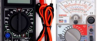
Thyristor check
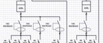
Before you buy a device, you need to know how to test a thyristor with a multimeter. The measuring device can only be connected to a so-called tester. The diagram by which such a device can be assembled is presented below:
Photo - thyristor tester
According to the description, it is necessary to apply a positive voltage to the anode, and a negative voltage to the cathode. It is very important to use a value that matches the resolution of the thyristor. The drawing shows resistors with a nominal voltage of 9 to 12 volts, which means that the tester voltage is slightly higher than the thyristor. After you have assembled the device, you can begin to check the rectifier. You need to press the button that sends pulse signals to turn it on.
Testing the thyristor is very simple; a button briefly sends an opening signal (positive relative to the cathode) to the control electrode. After this, if the running lights on the thyristor come on, the device is considered inoperative, but powerful devices do not always react immediately after the load arrives.
Photo - circuit tester for thyristors
In addition to checking the device, it is also recommended to use special controllers or a control unit for thyristors and triacs OWEN BOOST or other brands; it works approximately the same as a power regulator on a thyristor. The main difference is a wider range of voltages.
Video: operating principle of a thyristor
Specifications
Let's consider the technical parameters of the KU 202e series thyristor. This series presents domestic low-power devices, the main use of which is limited to household appliances: it is used to operate electric furnaces, heaters, etc.
The drawing below shows the pinout and main parts of the thyristor.
Photo - ku 202
- Set reverse on-state voltage (max) 100 V
- Closed voltage 100 V
- Pulse in open position - 30 A
- Repeated pulse in open position 10 A
- Average voltage <=1.5V
- Non-unlocking voltage >=0.2 V
- Set open current <=4 mA
- Reverse current <=4 mA
- Constant type unlocking current <=200 mA
- Set constant voltage <=7 V
- Turn-on time <=10 µs
- Turn-off time <=100 µs
The device turns on within microseconds. If you need to replace the described device, then consult a sales consultant at an electrical store - he will be able to select an analogue according to the diagram.
Photo - thyristor Ku202n
The price of a thyristor depends on its brand and characteristics. We recommend buying domestic devices - they are more durable and affordable. In spontaneous markets you can buy a high-quality, powerful converter for up to a hundred rubles.
Thyristors
Thyristors Thyristors
They are divided according to speed into low-frequency and high-frequency. They are used in various voltage and frequency converters, including for adjustable electric drives of flexible communication devices, power systems, DC power lines, in switching and control equipment, and in household appliances. Information about low-frequency thyristors is given in table. 14.1 and 14.2. High-speed thyristors are used in converters and other electrical installations where short turn-on and turn-off times are primarily required. They are distinguished by their high current carrying capacity at high frequencies (Table 14.3).
Symmetrical thyristors (triacs) have a symmetrical current-voltage characteristic and provide control in forward and reverse directions. Triacs are used in converters, voltage regulators, proximity switches and other devices (Table 14.4).
Information about thyristor diodes is given in table. 14.5.
The range of rectified (average) currents of power thyristors is from 10 to 4000 A, the range of reverse voltages is from several tens to 4000 V.
Permissible ambient temperature is from -50 to +45 °C at a pressure of 0.085-0.105 MPa and a relative humidity of 98%. Permissible transition temperature from -50 to
125 °C. Critical rate of voltage rise -
in the range from 50 to 1000 V/µs. The critical rate of current rise is in the range from 100 to 1000 A/µs.
The designs of power thyristors, as well as diodes, are mainly pin and tablet.
Types of coolers used: 0131—0281, OA, etc.
Designation of main parameters
Pmax is the highest long-term power dissipation. lOS - current in the open state (average) constant.
lopsm—maximum average current in the reverse conducting state (for thyristor diodes).
lЗС - current in the closed state is constant.
Uу is constant control voltage.
Uoc is the voltage across the thyristor in the open state.
U3C - long-term permissible repetitive reverse voltage in the closed state.
ton—on time.
Table 14.1
Thyristors type KU
Device type | |||||||||
| 2U202D | 20I | 10,0 | 10 | 1,5 | 100 | <7 | 5 | — | 150 |
| 2U202D1 | 20I | 10,0 | 10 | 1,5 | 100 | <7 | 5 | — | 150 |
| 2U202E | 20I | 10,0 | 10 | 1.5 | 100 | <7 | 5 | — | 150 |
| 2U202E1 | 20I | 10,0 | 10 | 1,5 | 100 | <7 | 5 | — | 150 |
| 2U202Zh | 20I | 10,0 | 10 | 1,5 | 200 | <7 | 5 | — | 150 |
| 2U202Zh1 | 20I | 10,0 | 10 | 1.5 | 200 | <7 | 5 | — | 150 |
| 2U202I | 20I | 10,0 | 10 | 1,5 | 200 | <7 | 5 | — | 150 |
| 2U202I1 | 20I | 10,0 | 10 | 1.5 | 200 | <7 | 5 | — | 150 |
| 2U202K | 20I | 10,0 | 10 | 1,5 | 300 | <7 | 5 | — | 150 |
| 2U202K1 | 20I | 10,0 | 10 | 1,5 | 300 | <7 | 5 | — | 150 |
| 2U202L | 20I | 10,0 | 10 | 1.5 | 300 | <7 | 5 | — | 150 |
| 2U202L1 | 20I | 10,0 | 10 | 1,5 | 300 | <7 | 5 | — | 150 |
| 2U202M | 20I | 10,0 | 10 | 1,5 | 400 | <7 | 5 | — | 150 |
| 2U202M1 | 20I | 10,0 | 10 | 1,5 | 400 | <7 | 5 | — | 150 |
| 2U202N | 20I | 10,0 | 10 | 1,5 | 400 | <7 | 5 | — | 150 |
| 2U202N1 | 20I | 10,0 | 10 | 1.5 | 400 | <7 | 5 | — | 150 |
| KU215A | 40 | 10,0 | 10I | 3,0 | 1000I | <50I | 500 | 1000 | 150 |
| 2U215A | 40 | 10,0 | 10I | 3,0 | 1000I | <50I | 500 | 1000 | 150 |
| KU215B | 40 | 10,0 | 10I | 3,0 | 800I | <50I | 250 | 600 | 150 |
| 2U215B | 40 | 10,0 | 10I | 3,0 | 800I | <50I | 250 | 600 | 150 |
| KU215V | 40 | 10,0 | 10I | 3,0 | 600I | <50I | 250 | 400 | 200 |
| KU222A | 150 | 10 | 10I | 3,5 | 2000I | <50I | 200 | 1000 | 170 |
| 2U222A | 150 | 10 | 10I | 3,5 | 2000I | <50I | 200 | 1000 | 170 |
| KU222B | 150 | 10 | 1OI | 3,5 | 2000I | <50I | 200 | 1000 | 300 |
| 2U222B | 150 | 10 | 10I | 3,5 | 2000I | <50I | 200 | 1000 | 300 |
| KU222V | 150 | 10 | 1OI | 3,5 | 1600I | <50I | 200 | 1000 | 170 |
| 2U222V | 150 | 10 | 1OI | 3,5 | 1600I | <50I | 200 | 1000 | 170 |
| KU222G | 150 | 10 | 1OI | 3,5 | 1600I | <50I | 200 | 1000 | 300 |
| 2U222G | 150 | 10 | 1OI | 3,5 | 1600I | <50I | 200 | 1000 | 300 |
| KU222D | 150 | 10 | 1OI | 3,5 | 1200I | <50I | 200 | 1000 | 170 |
| KU222E | 150 | 10 | 1OI | 3,5 | 1200I | <50I | 200 | 1000 | 300 |
| 2U229A | 150I | 200I | 1,0 | 50I | 1000 | <20I | 50 | 500 | 15 |
| 2U229B | 150I | 200I | 1,0 | 50I | 1000 | <20I | 50 | 500 | 35 |
| 2U229V | 150I | 200I | 1,0 | 50I | 1000 | <20I | 50 | 500 | 35 |
| 2U229G | 150I | 200I | 1,0 | 50I | 1000 | <20I | 50 | 500 | 50 |
| 2U229D | 150I | 200I | 1,0 | 50I | 1000 | <20I | 50 | 500 | 50 |
| 2U229E | 150I | 200I | 1,0 | 50I | 800 | <20I | 50 | 500 | 15 |
| 2U229Zh | 150I | 20OG | 1,0 | 50I | 300 | <20I | 50 | 500 | 50 |
| 2U229I | 150I | 200I | 1,0 | 50I | 800 | <20I | 50 | 500 | 50 |
| 2U229K | 150I | 200I | 1,0 | 50I | 600 | <20I | 50 | 500 | 15 |
| 2U229L | 150I | 200I | 1,0 | 50I | 600 | <20I | 50 | 500 | 50 |
| 2U229M | 150I | 200I | 1,0 | 50I | 1000 | <20I | 50 | 500 | 35 |
| 2U229N | 150I | 200I | 1,0 | 50I | 800 | <20I | 50 | 500 | 35 |
| KU701A | 100 | 20 | 6,0 | 3,0 | 800 | 3/5 | 100 | 100 | 30 |
| 2U701A | 100 | 20 | 3,5 | 2,0 | 800 | <3,5 | 120 | 100 | 30 |
| KU710B | 100 | 20 | 6,0 | 2,0 | 800 | 3/5 | 100 | 100 | 60 |
| 2U701B | 100 | 20 | 3,5 | 2,0 | 800 | <3,5 | 120 | 100 | 40 |
| KU701V | 100 | 20 | 6,0 | 3,0 | 800 | 3/5 | 100 | 100 | 40 |
| 2U701V | 100 | 20 | 3,5 | 2,0 | 600 | <3,5 | 120 | 100 | 30 |
| KU701G | 100 | 20 | 6,0 | 2,0 | 800 | 3/5 | 100 | 100 | 120 |
| 2U701G | 100 | 20 | 3,5 | 2,0 | 600 | <3,5 | 120 | 100 | 40 |
| KU701D | 100 | 20 | 6,0 | 3,0 | 600 | 3/5 | 100 | 100 | 30 |
| KU701E | 100 | 20 | 6,0 | 2,0 | 600 | 3/5 | 100 | 100 | 60 |
| KU701ZH | 100 | 20 | 6,0 | 3,0 | 600 | 3/5 | 100 | 100 | 40 |
| KU701I | 100 | 20 | 6,0 | 2,0 | 600 | 3/5 | 100 | 100 | 120 |
| KU702A | 150 | 20 | 20I | 3,5 | 200OP | <7 | 200 | 100 | 150 |
| 2U702A | 150 | 20 | 15I | 3,5 | 2000I | <7 | 120 | 100 | 135 |
| KU702B | 150 | 20 | 20I | 3,5 | 2000I | <7 | 200 | 100 | 250 |
| 2U702B | 150 | 20 | 15I | 3,5 | 2000I | <7 | 250 | 100 | 250 |
| KU702V | 150 | 20 | 20I | 3,5 | 1600I | <7 | 200 | 100 | 150 |
| 2U702V | 150 | 20 | 15I | 3,5 | 1600I | <7 | 120 | 100 | 250 |
| KU702G | 150 | 20 | 20I | 3,5 | 1600I | <7 | 200 | 100 | 250 |
| 2U702G | 150 | 20 | 15I | 3,5 | 1600I | <7 | 250 | 100 | 250 |
| KU702D | 150 | 20 | 20I | 3,5 | 1200I | <7 | 200 | 100 | 150 |
| KU702E | 150 | 20 | 20I | 3,5 | 1200I | <7 | 200 | 100 | 250 |
| KU706A | 150 | 40 | 20I | 3,0 | 1600I | 25/40I | 200 | 1000 | 150 |
| 2U706A | 150 | 40 | 1,5 | 2,5 | 1600I | 25/40I | 200 | 1000 | 130 |
| KU706B | 150 | 40 | 20I | 3,0 | 1200I | 25/40I | 200 | 1000 | 150 |
| 2U706B | 150 | 40 | 1,5 | 2,5 | 1200I | 25/40I | 200 | 1000 | 130 |
| KU706V | 150 | 40 | 20I | 3,0 | 1000I | 25/40I | 200 | 1000 | 150 |
Table 14.2
Low frequency thyristors
| Device type | lOCM, A | lZSM, mA | lON, mA | Uocm, V | U3CM, IN | UyM, V | ton, ISS | Recommended Cooler Type |
| 1112-10 | 10 | 2,5 | 100 | 1,85 | FROM | 7,5 | 10 | 011-60 |
| T112-15 | 16 | 2,5 | 100 | 1,85 | 100 | 7,5 | 10 | 011-60 |
| Т122-20 | 20 | 3,0 | 130 | 1,75 | BEFORE | 7,5 | 10 | 0221-60 |
| 1122-25 | 25 | 3,0 | 130 | 1,75 | 1200 | 7,5 | 10 | 0221-60 |
| T132-40 | 40 | 5,0 | 150 | 1,75 | from | 9,0 | 10 | 0231-80 |
| 1132-50 | 50 | 5,0 | 150 | 1,75 | 100 | 9,0 | 10 | 0231-80 |
| T142-63 | 63 | 5,0 | 210 | 1,65 | BEFORE | 10,0 | 10 | 0241-80 |
| T142-80 | 80 | 6,0 | 210 | 1,65 | 200 | 10,0 | 10 | 0241-80 |
| T151-100 | 100 | 13 | 700 | 1,85 | from | 5,5 | 25 | 0151-80 |
| Т161-125 | 125 | 15 | 700 | 1,75 | 300 | 5,5 | 25 | 0171-80 |
| T161-160 | 160 | 15 | 700 | 1,75 | 5,5 | 25 | 0171-80 | |
| T171-200 | 200 | 30 | 700 | 1,75 | before | 5,5 | 25 | 0181-110 |
| Т171-250 | 250 | 30 | 700 | 1,75 | 1600 | 5,5 | 25 | 0181-110 |
| T171-320 | 320 | 30 | /00 | 1,60 | 5,5 | 25 | 0181-110 | |
| Thyristors of cellular design | ||||||||
| TSh-200 | 200 | 15 | 700 | 1,9 | 400—1600 | 9,0 | 25 | 0123-100 |
| T132-250 | 250 | 15 | 700 | 1,75 | 400-1200 | 9,0 | 25 | 0123-100 |
| T123-320 | 320 | 15 | 700 | 1,65 | 400-800 | 9,0 | 25 | 0123-100 |
| Т133-320 | 320 | 35 | 700 | 2,0 | 900—2000 | 9,0 | 25 | 0143-150 |
| Т133-400 | 400 | 30 | 700 | 1,75 | 400—1600 | 9,0 | 25 | 0143-150 |
| T143-400 | 400 | 50 | 700 | 2,15 | 1800-2400 | 9,0 | 30 | 0243-150 |
| P43-500 | 500 | 30 | 700 | 1,80 | 400-1600 | 9,0 | 25 | 0243-150 |
| Т143-630 | 630 | 30 | 700 | 1,75 | 400-1200 | 9,0 | 25 | 0243-150 |
| Т153-630 | 630 | 50 | 700 | 2,1 | 1300—2400 | 9,0 | 30 | 0153-150 |
| Т153-800 | 800 | 50 | 700 | 1,9 | 1000—1800 | 9,0 | 30 | 0153-150 |
| T253-800 | 800 | 70 | 700 | 2,1 | 2000-2400 | 9,0 | 30 | 0153-150 |
| T253-1000 | 1000 | 70 | 700 | 1.8 | 1000—1800 | 9,0 | 30 | 0153-150 |
| T253-1250 | 1250 | 70 | 700 | 1,6 | 400—1200 | 9,0 | 30 | 0153-150 |
| Low-frequency avalanche thyristors | ||||||||
| TL171-250 | 250 | 35 | 600 | 2,05 | 700- | 6,0 | 10 | 0281-80 |
| TL171-320 | 320 | 35 | 600 | 1,65 | -1100 | 6,0 | 10 | 0281-110 |
Table 14.3
High-speed thyristors TB
| Device type | lOCM, A | lZSM, mA | lON, mA | Uocm, V | U3CM, IN | UyM, V | ton, ISS | Recommended Cooler Type |
| TB151-50 | 50 | 20 | 300 | 2,50 | 500- | 5 | 2 | 0151-80 |
| TB151-63 | 60 | 20 | 300 | 2,15 | 5 | 2 | 0151-80 | |
| TB161-80 | 80 | 30 | 400 | 2,60 | 5 | 2 | 0161-80 | |
| TB161-100 | 100 | 30 | 400 | 2,15 | BEFORE | 5 | 2 | 0161-80 |
| TB171-160 | 160 | 40 | 500 | 2,0 | 5 | 2 | 0181-110 | |
| TB 171-200 | 200 | 40 | 500 | 1,75 | -1200 | 5 | 2 | 0181-110 |
| Thyristors of tablet design | ||||||||
| TB 133-200 | 200 | 40 | 500 | 2,4 | 600- | 5 | 2 | |
| TB 133-250 | 250 | 50 | 500 | 2,0 | 5 | 2 | ||
| TB143-320 | 320 | 50 | 600 | 2,5 | BEFORE | 5 | 2,5 | 0343-150 |
| TB 143-400 | 400 | 70 | 600 | 2,1 | 5 | 3,2 | ||
| TB 153-630 | 630 | 40 | 700 | 2,2 | -1200 | 5 | 3,2 | |
| TB153-800 | 800 | 70 | 700 | 2,2 | 600- | 5 | 3,2 | |
| TB253-800 | 800 | 70 | 700 | 1,8 | 5 | 4,0 | 0350-350 | |
| TB253-1000 | 1000 | 70 | 700 | 2,25 | -1400 | 5 | 4,0 |
Table 14.4
Symmetrical thyristors TS
| Device type | lOCM, A | lZSM, mA | lON, mA | Uocm, V | U3CM, IN | UyM, V | ton, ISS | Recommended Cooler Type |
| T.161-150 | 160 | 15 | 500 | 1,75 | from200 | 8,5 | 20 | 0171-80 |
| GS 161-200 | 200 | 15 | 500 | 1,6 | 8,5 | 20 | 0171-80 | |
| GS 171-250 | 250 | 25 | 500 | 1,7 | up to 1200 | 8.5 | 20 | 0181-80 |
| GS 171-320 | 320 | 25 | 500 | 1,5 | 8,5 | 20 | 0181-80 |
Table 14.5
Fast-switching thyristor-diodes TD4
| Device type | lOCM, A | lZSM, mA | lON, mA | Uocm, V | U3CM, IN | UyM, V | ton, ISS | Recommended Cooler Type |
| TD4171-125/50 | 125 | 50 | 350 | 2,2 | 1600- | 5 | 32- | 0181-110 |
| TD4171-160/63 | 160 | 63 | 350 | 2,2 | -1600 | 5 | -63 | 0181-110 |
| TD4153-320/125 | 320 | 125 | 350 | 2,7 | 600- | 6 | 32- | 0153-150 |
| TD4153-400/160 | 400 | 160 | 350 | 2,7 | -1600 | 6 | -63 | 0153-150 |
Sketches of some types of thyristors are shown in Fig. 14.1.
Information about thyristors is also given in [8, 28, 29, 30,
46, 48].
← Previous | Next → … contents …