In this article we will talk about the Darlington transistor or Darlington pair, give some example circuits, show applications, advantages and disadvantages.
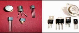
There are a wide variety of Darlington transistors available in the market today, which vary in conductivity, collector current, power dissipation, package type, maximum CE voltage, etc.
These transistors are found in various types of devices such as power regulators, motor controllers, audio amplifiers, etc. Many optical isolator circuits are made with Darlington transistors to have high current carrying capacity at the output stage.
Why do we use Darlington transistor?
As is known, to switch a transistor into conduction mode, a small base current is required in a common-emitter circuit. Sometimes this small base current (current gain) may not be enough to drive the transistor into conduction.
The current gain or beta of a transistor is the ratio of the collector current to the base current.
Transistor gain or current gain (β) = load or collector current / input or base current.
Load current = current gain (β) × base current
For a normal transistor, the value of β is approximately 100. The above ratio indicates that the load current is 100 times the base current of the transistor.
Transistor tester / ESR meter / generator
Multifunctional device for testing transistors, diodes, thyristors...
More details
Consider the schematic diagram below. Here a transistor with a variable resistor connected between the power supply and the base of the transistor is used to change the brightness of the lamp.
In this circuit, the base current is the only factor that determines the current flowing through the collector-emitter. Thus, by changing the resistance of the variable resistor, you can change the brightness of the lamp.
If the resistance value of the variable resistor is greater, then the base current decreases - the transistor turns off. When the resistance is too low, enough current will flow through the base, which will cause the collector-emitter current to increase, causing the lamp to shine brighter. This is an amplification of the current in the transistor.
In the above example, we saw driving a load (lamp) using a single transistor. But in some circuits, the input base current from the source may not be sufficient to drive the load. We know that the amount of current flowing through the collector-emitter is the product of the base current and the gain of the transistor.
Since increasing the current from the source is not possible, the only way to increase the load current is to increase the gain of the transistor. But for each transistor this is a constant coefficient. However, we can increase the gain by using a combination of two transistors. This configuration is called the Darlington configuration.
A Darlington transistor is a connection of two transistors in a certain way. A pair of bipolar transistors provides very high current amplification compared to a single standard transistor as mentioned above.
A pair of these transistors can be PNP or NP. The figure below shows the Darlington pair configuration with NPN as well as PNP transistors.
Sensitivity
The sensitivity of the transmitter largely depends on the value of the load resistor R1 of the electret microphone. We used 39k ohms in the prototype because the microphone we used was very sensitive. If you want to increase sensitivity, then the resistance of this resistor can be reduced to 33 kOhms, but do not go lower.
Electret microphones come in different sizes. They all work on the same principle - they generate an output signal when voltage is applied. Some of them have high sensitivity, while others have extremely low sensitivity. It's impossible to tell the difference without actually testing them.
Infrared heater with thermostat + lamp
Quick heating of the room, individual temperature in each room…
More details
Electret microphones do not produce voltage or current, but rather vary the voltage across a load resistor. This is why a load resistor is needed in series with one of the pins.
Example of a Darlington transistor circuit
Consider the following circuit where a Darlington pair is used to switch a load that is rated at 12V and 80W. Let's take the current amplification of the first and second transistors as 50 and 60, respectively. Thus, the base current required to fully turn on the lamp is calculated as follows.
The collector current is equal to the load current,
IC = 80/12 = 6.67 A
The output current of the Darlington transistor is given by Ic = IB (β 1 + β 2 + β 1 β 2 ),
IB = IC / (β 1 + β 2 + β 1 β 2 )
Current gain, β1 = 50 and β2 = 60
So, IB= 6.67 / (50 + 60 + (60 × 50))
IB = 2.2 mA
From the above calculation it is clear that with a small base current we can switch large loads. This small base current can be supplied from any microcontroller output or any digital logic circuits.
Analogs
Silicon transistors with an NPN structure, epitaxial-planar, intended for use in switching power supplies, ballasts, electric motor control circuits, etc., and general-purpose equipment may be suitable for replacement.
Domestic production
Transistors similar in parameters to the 13003 series (MJE13003).
| Type | PC, W | UCB, B | UCE, V | UBE, B | IC, A | UCE(sat), V | Tj, °С | fT, MHz | hFE | ton / ts / tf, μs | Frame |
| MJE13003 | 40 | 700 | 400 | 9 | 2 | 0,6 | 150 | 4 | 5…40 | — / 3,5 / 1 | TO-126 |
| KT8170A | 40 | 700 | 400 | 9 | 2,25 | 3 | 150 | 4 | 5…40 | 1,1 / 4 / 0,7 | TO-126 |
| KT859A | 40 | 800 | 800 | 10 | 3 | 1,5 | 150 | ˃ 3,3 | ˃ 10 | 0,35 / 3,3 / 0,35 | TO-220AB |
| KT841A/V | 50 | 600/800 | 350 | 5 | 10 | 1,5 | 150 | 10 | 12…45 | 0,08 / 0,8 / 0,2 | TO-3 |
| KT8118A | 50 | 900 | 800 | — | 3 | ˂ 2,0 | 150 | ˃ 15 | 10…40 | — | TO-220 |
| KT8120A | 60 | 600 | 450 | 5 | 8 | 1 | 150 | 20 | ˃ 10 | — / 2 / 0,2 | TO-220 |
| KT840A/B/V | 60 | 900/750/800 | 400/350/375 | 5 | 6 | 0,6 | 150 | 8…15 | 10…60 | 0,2 / 3,5 / 0,6 | TO-3 |
| KT868A/B | 70 | 900/750 | 400/375 | 5 | 6 | 1,5 | 150 | ˃ 8 | 10…100 | — | TO-3PML |
Foreign production
Analogs of transistor E13003 (MJE13003).
| Type | PC, W | UCB, B | UCE, V | UBE, B | IC, A | UCE(sat), V | Tj, °С | fT, MHz | hFE | ton / ts / tf, μs | Frame |
| MJE13003 | 40 | 700 | 400 | 9 | 2 | 0,6 | 150 | 4 | 5…40 | — / 3,5 / 1 | TO-126 |
| 3DD1910 | 40 | 700 | 400 | 9 | 2,5 | 1 | 150 | 5 | 15…30 | 1 / 5 / 0,8 | TO-126A |
| 3DD13005A7 | 40 | 800 | 400 | 9 | 3 | 0,6 | 150 | 5 | 15…35 | 1 / 5 / 1 | TO-126F |
| WBR13005D1 | 40 | 700 | 400 | 9 | 4 | 1 | 150 | 4 | 10…40 | — / 3,6 / 1,6 | TO-126 |
| BTN3A60T3 | 40 | 900 | 700 | 9 | 3 | 0,6 | 150 | 4 | 10…40 | — | TO-126 |
| HLD133D | 35 | 700 | 400 | 9 | 2 | 1 | 150 | — | 5…40 | — / 4 / 0,8 | TO-126 |
| ST13007DFP | 36 | 700 | 400 | 9 | 8 | 3 | 150 | 4 | 8…40 | — / 2,2 / 0,15 | TO-220FP |
| BUL310FP | 36 | 1000 | 500 | 9 | 5 | 1,1 | 150 | — | 10 | — / 1,8 / 0,5 | TO-220FP |
Analogs of transistors 13003BR (MJE13003BR) and 13003T (KSE13003T).
| Type | PC, W | UCB, B | UCE, V | UBE, B | IC, A | UCE(sat), V | Tj, °С | fT, MHz | hFE | ton / ts / tf, μs | Frame |
| MJE13003BR | 30 | 600 | 400 | 9 | 2 | 0,85 | 150 | — | 5…40 | — / 3 / 0,8 | TO-126 |
| BLD123D | 30 | 600 | 400 | 9 | 2 | 0,9 | 150 | — | 5…40 | — / 4 / 0,8 | TO-126 |
| KSE13003T | 30 | 700 | 400 | 9 | 1,5 | 3 | 150 | 4 | 5…40 | 1,1 / 4 / 0,7 | TO-220 |
| FJPE3305 | 30 | 700 | 400 | 9 | 4 | 1 | 150 | 4 | 8…40 | 0,8 / 4 / 0,9 | TO-220F |
| KSH13005AF | 30 | 700 | 400 | 9 | 4 | 1 | 150 | 4 | 8…60 | 0,8 / 4 / 0,9 | TO-220F |
| MJE13005AF | 30 | 800 | 400 | 10 | 5 | 1 | 150 | 4 | 8…35 | 0,15 / 5 / 0,8 | TO-220IS |
| MJE13005F | 30 | 700 | 400 | 9 | 4 | 1 | 150 | 4 | 10…35 | 0,8 / 4 / 0,9 | TO-220IS |
| STD13005F/FC | 30 | 700 | 400 | 9 | 4 | 1 | 150 | 4 | 8…40 | 0,8 / 4 / 0,9 | TO-220F-3L |
| STL128DFP | 30 | 700 | 400 | — | 4 | 1,5 | 150 | — | 10…32 | — / 0,6 / 0,1 | TO-220FP |
| TS13005CI | 30 | 700 | 400 | 9 | 4 | 1 | 150 | 4 | 8…40 | 0,7 / 3 / 0,5 | ITO-220 |
| TSC236CI | 30 | 700 | 400 | 9 | 4 | 1,3 | 150 | — | 8…32 | 0,5 / 3 / 0,5 | ITO-220 |
| BUL128FP | 31 | 700 | 400 | 9 | 4 | 1,5 | 150 | — | 10…45 | — / 2,9 / 0,4 | TO220FP |
Note: the table data is obtained from the datasheet of the manufacturing companies.
Applications of Darlington transistor
Darlington transistors are primarily used in switching and amplification circuits to provide very high DC gain. Some of the key circuits are high- and low-side switches, sensor amplifiers, and audio amplifiers. For photosensitive devices, photodarlingtons are used. Let's look at the operation of the Darlington transistor using a specific example.
Darlington transistor (NPN) as a switch
The figure below shows driving an LED using a Darlington transistor. The switch on the base can also be replaced with a touch sensor, so that when you touch the sensor, the LED will light up. The 100k ohm resistor acts as a protection resistor for the transistor pair.
Darlington Transistor as a Switch
When the switch is closed, a voltage greater than 1.4 V is applied to the Darlington transistor. This causes the Darlington pair to become active and pass current through the load. This causes the LEDs to glow very brightly, even when the base resistance changes.
When the switch is open, both bipolar transistors are in cutoff mode and the current through the load is zero. Thus, the LED goes out.
It is also possible to use a Darlington pair to drive inductive loads such as relays, motors. Compared to a single transistor, driving inductive loads using a Darlington pair is more efficient because it provides high load current with low base input current.
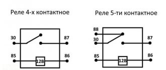
The figure below shows a Darlington pair that drives a relay coil. When switching an inductive load, a diode must be connected in parallel to protect the circuit from induced currents. As in the LED circuit above, the relay coil is energized when base current is applied. We can also use a DC motor as an inductive load instead of a relay coil.
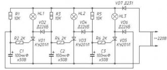
Symmetrical transistor multivibrator
The principle of operation is to transition from one unstable state (Q1 closed, Q2 open) to another (Q1 open, Q2 closed).
Let's start with the first state: Q1 is closed, Q2 is open.
Capacitor C1 quickly charges through the “smaller” resistor R4 and the base junction Q2. At the same time, through open Q2, through the “larger” resistor R2, C2 is slowly discharged, the negative voltage on which keeps Q1 in a locked state.
In the process of further recharging C2, a positive unlocking voltage appears at the base of Q1, and Q1 begins to open. The current through it increases, the voltage at the collector of Q1 and the base of Q2 decreases, which causes it to turn off.
The voltage on the collector of Q2 increases and through the capacitor C2 opens Q1 even more.
The process of opening Q1 accelerates the closing of Q2, and the process occurs almost like an avalanche, and the transition from one state to another occurs very quickly.
Voltages on capacitor C1, base-emitter and collector-emitter of transistor Q2 Voltages on capacitor C1, base-emitter and collector-emitter of transistor Q2
In general, transistors periodically open and close each other.
Now a little about the calculation of elements.
The period consists of two parts t1 and t2, depending on the resistances R2, R3 and capacitances C1, C2:
t1 = 0.7 x R3 x C1;
t2 = 0.7 x R2 x C2
For example, in the circuit in the picture above, the period is t1 + t2 = 2*0.7*22 kOhm*0.1 µF = 3.08 ms.
Period 3.3 ms Period 3.3 ms
The duration of the decay of the pulses depends on the resistance of resistors R1 and R4: the lower the resistance, the faster the decay.
When R1 = R4 = 470 Ohm When R1 = R4 = 470 Ohm
The main disadvantage of this scheme is the slow declines. This shortcoming is corrected in the diagram:
Darlington transistor (PNP) as a switch
We can use PNP transistors as a Darlington pair, but NPN transistors are most commonly used. There is not much difference in the circuit using NPN or PNP. The figure below shows a simple sensor circuit that generates an alarm using a Darlington pair.
This circuit is a simple water level indicator using a Darlington pair as a switch. We know that this transistor configuration provides a large collector current so it can drive the buzzer at the output.
When the water level is insufficient to close the sensor, the Darlington transistor is turned off. Therefore, the circuit is broken and no current flows through it.
As the water level rises, the sensor closes, resulting in the required base current being supplied to the Darlington pair. Consequently, the circuit is completed and load current flows so that the buzzer sounds.
Multivibrator frequency
Note that the charging of the capacitor through Rb continues for a relatively long time, but the switching of transistors occurs almost instantly. Therefore, the multivibrator generates rectangular pulses. And their frequency is determined by the charging time of the capacitors:
f = 1.443 / (C1*Rb1 + C2*Rb2)
where f is frequency (Hz), C is capacitance in farads, R is resistance in ohms
It remains to add a couple of technical notes. First: the multivibrator has two outputs, the signal can be removed from both the T1 collector and the T2 collector. These two signals are out of phase, some circuits take advantage of this property and use both signals. When connecting a load, it is important not to bypass the transistor, otherwise there is a risk of distorting the operation of the multivibrator, or even completely disrupting generation. It is best to connect the load in parallel with the collector resistance.
Well, the second note. It’s obvious, but without mentioning it, the article would be incomplete: we are analyzing here a circuit based on npn transistors, but in the same way, a multivibrator can be built on pnp transistors by changing the power polarity. And also on radio tubes, operational amplifiers, logic elements, etc. - the main thing is that there are two amplification stages covered by the OS. One of such schemes will be given below.
We recommend reading: LM358 microcircuit: datasheet in Russian, application, analogues, pin assignments
Output pulse shapes
The output voltage is approximately a square waveform. Considered below transistor Q1. In state 1, Q2 is base-emitter in reverse direction and capacitor C1 is “decoupled” from ground. The output voltage of the switched-on transistor Q1 quickly changes from high (limits: more than 1 kV) to low (limits: up to 250 V), since this is a low-resistive output, it loads a high impedance load (series-connected capacitors C1 and high-resistance base resistor R2). During state 2, Q2's base-emitter is forward biased and capacitor C1 is "connected" to ground. The output voltage of off transistor Q1 changes exponentially from low to high, since it is a relatively high resistive output, the low impedance load (capacitance C1) is loaded. This is for the output voltage R 1 C 1 of the integrating circuit. To get close to the required signal area, the resistor collector current needs to be below the resistance. The resistor base must be low enough to saturate the transistors at the end of recovery (RB <β.rc="">
Initial nutrition
However, if the temporary storage circuit and the high base are longer than required to fully charge the capacitors, then the circuit will remain in a stable state, both with the base at 0.6 V and the collectors at 0 V, and both capacitors discharging to -0 .6 V. This can happen at startup without external intervention if R and C are very small.
Protective components
Although not fundamental to circuit operation, diodes in series with the base or emitter of the transistors are needed to prevent the base-emitter transition, driving in the opposite direction of breakdown when the supply voltage exceeds V EB breakdown voltage, typically around 5 -10 volts for general purpose silicon transistors.
Advantages of a Darlington pair
A Darlington pair has several advantages over a standard single transistor. Here are some of them:
- It provides very high current gain than a standard single transistor
- It provides very high input impedance or good impedance conversion.
- They can be two separate transistors or supplied in one package.
- Simple and convenient circuit configuration as only a few components are used.
- In the case of a photodarlington pair, the external noise is much less compared to a phototransistor with an external amplifier.
Disadvantages of a Darlington pair
- Low switching speed
- Bandwidth is limited
- At certain frequencies, this configuration introduces a phase shift in the negative feedback loop.
- The required base-emitter voltage is high and twice that of a standard transistor.
- High power dissipation due to high saturation voltage.
- The total leakage current is high because the leakage current of the first transistor is amplified by the next transistor. This is why three or more Darlington steps are not possible.
Hence, the Darlington pair is very useful in most applications as it provides high current gain at low base currents.
Although this has some limitations, these pairs are widely used in applications where high frequency response is not required but high levels of current gain are required. In case of audio power amplifier circuits, this configuration provides better power output.
Is it possible to assemble the circuit yourself?
Yes, you can. This device is perfect for beginners and those interested in electronics.
This circuit has few details, but it works simply and reliably. You can assemble the circuit by mounted mounting, on a circuit board, or try your hand at making a printed circuit board - laser ironing technology (LUT).
From parts, KT315 transistors can be taken from any that are similar in analogues. Resistors are 0.125 W, and capacitors are no less than the supply voltage. You can power it from a LBP (laboratory power supply) or from a +12 V battery or charger.
Regarding the frequency setting. You can change the frequency using capacitance and resistance. It's much easier with resistors. It is enough to simply replace a regular resistor with a variable one (not a tuning one). It is enough to use 1-2 or 3-1 from contacts 1-2-3.
The greater the resistance, the smaller the adjustment step. You can draw wires from the variable resistor and visually observe the change in frequency.