In any technology, LEDs are used to display operating modes. The reasons are obvious - low cost, ultra-low power consumption, high reliability. Since the indicator circuits are very simple, there is no need to purchase factory-made products.
From the abundance of circuits for making a voltage indicator on LEDs with your own hands, you can choose the most optimal option. The indicator can be assembled in a couple of minutes from the most common radioelements.
All such circuits are divided into voltage indicators and current indicators according to their intended purpose.
Working with a 220V network
Let's consider the simplest option - phase checking.
This circuit is a current indicator light found on some screwdrivers. Such a device does not even require external power, since the potential difference between the phase wire and the air or hand is sufficient for the diode to glow.
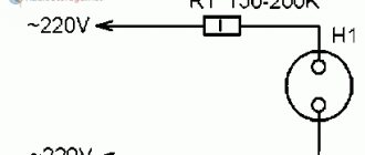
To display the mains voltage, for example, to check the presence of current in the socket connector, the circuit is even simpler.
The simplest current indicator on 220V LEDs is assembled using capacitance to limit the current of the LED and a diode to protect against reverse half-wave.
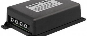
Voltage, current, power meter on DIN rail. Powerful stuff.
There have been numerous reviews of the popular Wattmeter here; I also needed such a device. But due to the specifics of my work, I decided to take it, so to speak, “for growth.” Below the cut you will find photos of the outside and inside, as well as small measurements. I have long thought about having a device for measuring power on my farm, I even thought about assembling it myself, but in the end I looked at a ready-made device. First of all, three things attracted me to this device, which fundamentally distinguish it from the well-known wattmeter, these are: LED indicator Current measurement up to 100 Amperes Possibility of mounting on a DIN rail.
Photo of packaging and brief description of the device
The meter arrived in a small box, on one of the sides it was written what the device can measure. Alternating voltage Alternating current Active power Apparent power Power factor.
On the other side of the package, brief main characteristics are indicated. Voltage 80-300 Volts Current 0-100 Amps
The dimensions of the packaging, as often happens, are matched closely, which is good. The device will not hang out in its “house” during the journey.
The entire kit consists of the meter itself and instructions, nothing more.
Instructions, there is more information here, but all of it is in English. But the performance characteristics can be distinguished without problems. Measurement accuracy - 1% ± 2 digits. Indication of voltage and current 4-digit 0.31-inch display. Indication of active and total power, as well as power factor - 5-digit 0.31-inch display. For a current of less than 10 Amps, the minimum display resolution is 0.01A, for a current of more than 10 Amps, correspondingly 0.1 A. Active power - 0-30000 W Total power - 0-30000 VA Power factor - 0.000-1.000 Measurement speed, 2 times per second. Dimensions - 54x80x64mm
The device is designed for installation on a standard DIN rail. Width 3 modules, or 54mm.
The device looks very neat. If it had the ABB or Lengrand logo on it, I would completely believe it. no burrs, flash, cracks, etc. At the top there are planned places for connecting an external sensor (the device has two modifications), I have a version with a built-in current transformer, so these places are closed.
At the back there is a latch for fixing the module on the DIN rail.
And here is the device itself. The top two indicators display voltage and current. The lower one can be switched to display modes of active, apparent power or power factor. The button is in the lower left corner. In the lower right there are three LEDs indicating what value is currently displayed. When power is applied, the device always starts with the active power displayed.
On the right side wall there is a wiring diagram for the device. Everything is concise and extremely clear.
Let's take a look inside the meter
Photo inside
Inside the device there are two boards, a current transformer, as well as a guide tube into which we insert the wire on which the current is measured.
The board with indicators is attached with four screws, the second board is attached with only one, although there is room for four. But I didn’t see any problems because of this, since there is no mechanical load on this board.
Power supply board and indication board.
And this is the main board, which deals with measurements and display. It is worth noting that all the boards are well washed from flux, there are no crookedly installed components, the soldering is neat, there are no complaints. The device uses only two microcircuits, the tm1640 display driver, and the bwl13118 controller, which handles everything else (ADC, mathematics). I couldn’t find data on it, if anyone knows what it is or what its analogue is, write, I’ll add it to the review. I suspect. that it could be some kind of PIC.
The terminals are quite simple and hold the wire well, especially since only the meter’s power goes through them.
The power supply is made according to a circuit with a quenching capacitor, capacity 0.82 μF, voltage 630 Volts, I was very pleased with the latter, they often save money and install 400 Volt capacitors.
The board also contains voltage measurement resistors and a load resistor for the current transformer. Unfortunately, there is no fuse.
Rectifier filter capacitor with a capacity of 470 μF for a voltage of 16 Volts. There are current limiting resistors.
First of all, I checked the accuracy of the input voltage measurement. The result was quite pleasing. Since the display accuracy is higher than that of my multimeter (3000 versus 1999), it is noticeable in the photo that when displaying higher than 0.5, the multimeter displays 1 plus sign, and below 0.5 the current one, i.e. averages over the larger value.
I have removed further accuracy checks under the spoiler.
For further testing, I prepared an additional piece of cable and a socket to make it more convenient to connect the loads.
The very first test surprised me somewhat, but not even because the device slightly underestimates the current, while it still fits within the accuracy declared by the manufacturer. I was surprised that when I connected a 150W incandescent lamp as a load, I saw a power of only 122W. No, I understand that the lamp is 20 years old, but I haven’t used it much, the rest of the time I use it only when checking power supplies and very rarely. In this case, it is not a device problem, but a load problem.
I have read several times that with current sensors of the type used here, to increase accuracy, it is desirable that the conductor on which the measurement takes place is located in the center of the hole of the current sensor. To do this, I took a piece of coaxial cable insulation, wrapped it on top of masking tape, in the place where the transformer is located, and also wound a little tape on the wire itself so that it would be as accurately as possible in class=”aligncenter” width=”800″ height= "600"[/img]
The measurement accuracy has actually increased slightly.
Since the load is active, the device shows total power, the same as active.
The power factor is correspondingly equal to unity.
Since I won’t be able to find a powerful load in the near future, I had to use the most powerful one that I found at home and that I can measure with a regular multimeter. An iron was used for this test. Fortunately, it was possible to measure the resistance of the heater and calculate the current, but disassembling a modern iron (to measure the resistance of the heater) turned out to be not so easy, so I limited myself to comparing the current with my multimeter. If we assume that the multimeter shows accurately, then the device under review lied by only 0.12A with a measurement range of up to 100A.
For further tests, I took out of storage a dial multimeter with hardware trueRMS, so to speak . This test clearly shows why to measure the current consumption of switching power supplies (without a Power Factor Corrector) you need a device with trueRMS. As a test, a switching power supply loaded with approximately 120 Watts is connected. The analog device and meter showed the same current of 0.7 A, a digital conventional multimeter underestimated the readings and showed 0.53 A. Before starting measurements, the needle in the analog multimeter was set to 0.
The total power was 166 VA.
The power factor is correspondingly 0.789
The needle of the device stands exactly at 0.7 Ampere; it would, of course, be better to use an appropriate digital device, but what are you rich in?
To increase the measured current, I added a load to the switching power supply and also connected a 150 (122) Watt incandescent lamp parallel to its input. The readings of the digital device are again underestimated, since the load has a capacitive component. The active load power is 276 W.
The total load power is 301 VA.
The power factor increased slightly due to the addition of the active load and amounted to 0.910
Since the arrow does not fall exactly on the scale division, I cannot say that the readings are practically accurate; rather, if there is a run-up, it tends to zero.
At this point I finish the accuracy check stage, if you have any ideas to check. offer.
Summary.
Pros:
High-quality production. I was not able to test the device at high currents, but the device passed the tests carried out, the results are above. Convenient design, sufficient functionality for such a device. Well-readable display (one of the reasons why I chose this option). Large current measurement range.
Minuses
Lack of fuse in the power supply circuit of the device. To increase measurement accuracy, it is advisable to place the wire being measured in the center of the hole.
My opinion. I am completely satisfied with the device, I will add a fuse later, I don’t see a big problem in this, I showed above how to place the wire in the center. It’s bad that we couldn’t test it at high currents, at least 40-50 Amps. But so far the readings are completely within the error declared by the manufacturer. The indicator is good (I didn’t really like devices with an LCD display). Yes, I completely forgot, heating of the device during measurements and operation was not noticed.
The meter is provided for review and testing by eachbuyer.
I hope this review was helpful. I think that there will be people who will find such a device useful.
You can save a little on your purchase
The store is holding a promotion, an 8% discount on all products when you enter the NEWORDER8
With this coupon the meter will cost about $20.
DC Voltage Check
Often there is a need to ring the low-voltage circuit of household appliances, or check the integrity of a connection, for example, a wire from headphones.
As a current limiter, you can use a low-power incandescent lamp or a 50-100 Ohm resistor. Depending on the polarity of the connection, the corresponding diode lights up. This option is suitable for circuits up to 12V. For higher voltages, you will need to increase the limiting resistor.
Indicator for microcircuits (logic probe)
If there is a need to check the performance of a microcircuit, a simple probe with three stable states will help with this. If there is no signal (open circuit), the diodes do not light up. If there is a logical zero on the contact, a voltage of about 0.5 V appears, which opens transistor T1; if there is a logical one (about 2.4 V), transistor T2 opens.
This selectivity is achieved thanks to the different parameters of the transistors used. For KT315B the opening voltage is 0.4-0.5V, for KT203B it is 1V. If necessary, you can replace the transistors with others with similar parameters.
Terminology
In numerous articles posted on the Internet, you can find the terms “voltage indicator”, “low voltage indicator”, “voltage indicator”. However, often no distinction is made between the areas of their use, and sometimes they are even identified. Let's try to understand this issue.
Numerous rules for the use of electrical protective equipment, which are constantly changing and republished, always use the term “voltage indicator”. In this case, all such devices are divided into bipolar ones, consisting of two bodies connected by a flexible insulated conductor; and single-pole, containing one body. The former operate on active current flowing through both bodies, and the latter operate on capacitive current flowing through the user’s body.
The widely used term “voltage indicator” refers specifically to the second type of indicator. Their early models were produced in the form of a screwdriver with an indicator light in the handle. Modern devices look more like a construction marker (though with a metal contact part at the end).
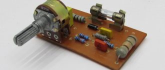
Option for car
A simple circuit for indicating the vehicle's on-board voltage and battery charge. The zener diode limits the battery current to 5V to power the logic chip.
Variable resistors allow you to set the voltage level to trigger the LEDs. It is better to carry out the setup from a network stabilized power source.
Please rate the article. We tried our best:)
Did you like the article? Tell us about her! You will help us a lot :)