The nuances of battery operation
The most common type is the lead-acid battery. The service life of the device is calculated on average for 5 years. Recharging such batteries requires using at least 10% of the current from the total capacity of the device.
For example, with an indicator of 75Ahh, a minimum current value of 7.5A is required for charging. If the current is higher, the battery will not fail, but the car may lose its brains.
Repairing the control unit for air conditioning, gearbox, alarm system, and so on is not a cheap pleasure.
A device with a voltage of 11.9-12.1 Volts is discharged; in working condition, the charge level should be 12.5-12.7 Volts.
What you need to know when charging a battery
When charging a car battery, it is important to follow a number of rules. This will help you extend your battery life and maintain your health:
- All lead batteries are charged with a current no higher than one tenth of the battery capacity. If you have a battery with a capacity of 60 A/h in your car, then the calculation of the charging current looks like this: 60/10 = 6 A.
- Explosive gases may be released during charging. This is especially true for serviceable batteries. One spark is enough for hydrogen accumulated in a garage or other room to explode. Therefore, you need to charge batteries in a well-ventilated area or on a balcony.
- Charging the battery is accompanied by the release of heat, so constantly monitor the temperature of the battery case by touch. If the battery becomes noticeably hot, immediately reduce the charging current or stop charging altogether.
- If the battery is serviceable, constantly monitor the electrolyte level in the banks and its density. During the charging process, the electrolyte “boils away” and the density increases. If the plates in the jar are exposed or the density rises above 1.29, and charging is not yet complete, add distilled water to the electrolyte.
- Do not overcharge the battery. The maximum voltage on it with the charger connected is 14.7 V.
- Do not allow the battery to be deeply discharged; recharge it periodically. If the voltage on the battery drops below 10.7 when the load is off, the battery will have to be thrown away.
The question of creating a simple battery charger with your own hands has been clarified. Everything is quite simple, all you have to do is stock up on the necessary tools and you can safely get to work.
Originally posted 2018-07-04 08:34:51.
Conditions for homemade battery charging
To charge the device, the following requirements must be met:
- Constant voltage setting – 14.4V;
- Possibility of charging for a long time;
- Automatic shutdown when maximum current values are exceeded;
- Protection against pole connection error. When connecting minus to plus, the charging process must be stopped.
Any violation of the above requirements may irreversibly damage your device.
Everything with your own hands
Thyristor pulse charger 10A on KU202
Hello. Today I will talk about a thyristor phase-pulse power regulator circuit that I have been using for a long time, which I will use as a charger for lead-acid batteries
I already wrote about charging with a thyristor. This charger is much better. I will begin the description of the KU202 thyristor charger with the advantages: - The charger can easily withstand a current of up to 10A (depending on the thyristor, in this case KU202) - The charge current is pulsed, which, according to many radio enthusiasts, will help with the service life of the battery - The circuit consists of easily accessible parts, you can assembled almost from trash. The charger circuit is easily repeatable and even a beginner can assemble it, if only he knew how to solder - And the last advantage is that this circuit does not require any gadgets. The circuit is already equipped with everything necessary so that hackers do not burn out either the battery or the circuit. The charger circuit has short circuit protection, reverse polarity protection, and a charging voltage limiter. Limiting the charging voltage makes it possible not to monitor the end of charging, but to leave charging uncontrolled for a long time; the circuit itself will turn everything off
Scheme of a thyristor charger on KU202 Let's consider the circuit of the charger. On the left, on Q2Q3 transistors, there is a circuit of a thyristor phase-pulse power regulator; there is a lot of information on the Internet about what this is. The adjustment of the opening phase and, accordingly, the charging current is regulated by variable resistor R4. Transistors Q2Q3 are an analogue of a unijunction transistor, which can be replaced with KT117 to simplify the circuit. I use a power thyristor KU202, it is available here and is powerful enough to charge car batteries with sufficient current. By the way, the charging current is set to 110 from the capacity.
The right side of the diagram is battery protection. Transistor Q1Q4 contains overvoltage protection, short circuit protection and polarity reversal protection. The circuit turns on only when a battery is connected to the charging output. Current flows through the divider R3R6, opening transistor Q1 and energizing the phase-pulse current regulator. Reverse polarity protection works like this. When the terminals are not connected correctly, the current flowing through the same divider turns off the transistor, so no current flows to the power regulator. The charging cut-off device works quite simply, when the end of charging voltage reaches 14.4V, the voltage on the divider R8R11 becomes sufficient to break down the zener diode, transistor Q4 opens, closing Q1. And the most important thing in the circuit is the transformer. The circuit is powered by a transformer with a voltage of 18-25V. In my case, during testing, I powered the charger from a Regulated AC source. Printed circuit board of a thyristor charger for car batteries
Download the printed circuit board of the thyristor charger. You can see how to make a printed circuit board with your own hands in the article How to make a printed circuit board.
At the output, the board has two LEDs to indicate battery connection. Green indicates a correctly connected battery, red indicates polarity is broken or polarity is reversed. It’s also a good idea to put a fuse on the output, just in case
Now about the tests. The circuit is soldered and assembled, the diode bridge and thyristor are installed on radiators, and the output wires are soldered.
The printed circuit board was used from old chargers and prepared for powerful resistors. But since I recalculated the values, now all resistors can be used at 0.25 W. I also used transistors like KT315 KT361, old but reliable. You can use KT3102 KT3107 KT814 KT815 KT816 KT817
I’ll carry out the tests on a gel battery, I’m too lazy to remove a normal battery from the car! In this photo, I intentionally connected the charger incorrectly, but nothing happened other than the red LED lighting up. That's the way it should be
Now I connected it correctly and the current started flowing. The photo shows the minimum current readings, but you can make it smaller by increasing the rating of R4, say up to 33 kOhm. I left the minimum current at 2A, since there is no point in setting a lower current for a car battery
And here the maximum current is 8A. This indicator is regulated by resistor R2. The smaller the resistor, the higher the maximum current. But you shouldn’t chase the current, since the KU202 will not draw more than 10A, and a current of 10A is quite enough to charge a battery with a capacity of 120Ah.
The photo shows an almost charged battery and it’s time to make just one adjustment, this is to set the maximum voltage. To do this, you need to wait until the battery is charged to 14.4V and use the variable resistor R8 to set the torque so that the voltage does not rise higher.
And the entire circuit is assembled, charging, charging, and protection are working. Let’s stop there for now, this circuit was assembled to recalculate the values of the resistors, tell you about the principle of operation and what I will do with it next, I will tell you in the article about the starting charger, but for now that’s all.
Thanks to the reader, I was able to find out the author of the modification of the automatic shutdown circuit, the author is master144, and the discussion on the forum is here
Do you want the same device? Write to me on my internal VKontakte email. And also subscribe to updates in the group, buttons at the top of the site, and you will always be aware of the latest updates From uv. Edward
Models of homemade battery chargers
Any homemade charger does not provide any guarantee of long-term operation. The main thing here is simplicity and efficiency. Next, let's look at examples of how you can charge a car battery yourself.
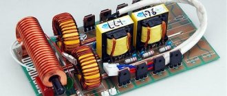
Features of regulators for primary transformers
The battery charging current is 10% of its capacity. This means that a battery with a capacity of 60Ah is charged with a current of no more than 6A. The charging voltage when the car is running is 14.5V. Given the required margin, the charger should be capable of delivering 10A at 16V.
A voltage reserve is necessary to regulate and limit the charging current.
In different models of devices it is done in different ways:
- Additional resistances. They turn on after the diode bridge. The simplest design, but with the largest dimensions.
- Transistors. High adjustment accuracy, but the most complex circuit that requires good cooling of power transistors.
- Thyristor control. Simple diagrams. The adjustment is carried out by a thyristor switch in the primary winding circuit or by thyristors installed instead of diodes in the rectifier bridge.
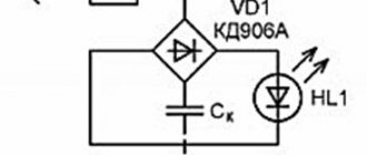
Using a lamp and a semiconductor diode
This method of recharging a battery device is relevant at home. To implement this, you must have a 220V outlet.
- The circuit elements include a standard 100-150 Watt incandescent lamp, a semiconductor diode, a socket plug and a cable with crocodile clips.
- In this connection, the diode serves as a voltage converter from AC to DC.
- To prevent a short circuit, it is enough to use a 10-15 A fuse. The lamp and diode must be connected to the “+” of the battery.
With a lamp power of 100 watts, the incoming current will be 0.17A. To achieve a value of 2A, you will need to charge the battery for at least 10 hours.
Most likely, it will not be possible to completely restore the charge of a dead battery, but it will be enough to start the car.
What is a triac
The thyristor has a drawback that complicates its use in an alternating current network - it passes through only one half-wave and the output produces a constant pulsating voltage instead of an alternating voltage. Therefore, these devices are used in pairs or together with a diode bridge. The triac is free from this drawback.
A triac is similar in appearance to a thyristor. Just like a thyristor, it opens with a current pulse flowing through the control electrode, but this device passes both half-waves through itself and is capable of operating in an alternating current network.
Schematic diagram of a triac current regulator for active and inductive loads. The design of a triac regulator is similar to a thyristor regulator. The difference is that the triac controls both polarities and therefore there is no need to use a diode bridge or back-to-back connection of elements.
In addition, the polarity of the control voltage does not matter for the triac, which simplifies the pulse control circuit.
Advice! To adjust the triac, you can use a dimmer from an incandescent lamp. To do this, it is connected between the anode and the control electrode of the power triac.
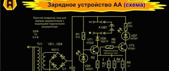
Charging model assembled from a PC power supply
The standard power supply for a personal computer is rated at 12 Volts. To charge the battery, we remind you that you will need at least 14.4 Volts.
First, all unnecessary wires are unsoldered; for charging you will only need green wires. The end of this cable is soldered to the negative contacts where the black wires exit.
- This circuit allows you to start the charger directly. The wires coming from the battery terminals are connected to the minus and plus on the power supply. The plus is soldered where the yellow cable exits, and the minus is soldered to the end of the black wire.
- Next, you need to regulate the power; a TL494 or TA7500 microcontroller is assigned to this characteristic in the power supply. We turn the board over and look for the leftmost leg of the microcircuit.
- 3 resistors are connected to the lower output of the microcontroller. You need to find a resistor connected to the terminal of the 12V block, unsolder it, and then measure the effective resistance.
To determine the required number of kOhms, a variable resistance resistor is soldered in place of the soldered resistor. We connect the power supply board to the network by hooking up a multimeter to it.
Using a variable resistor, we obtain the minimum required voltage value of 14.4 Volts. Once this voltage is reached, we solder the variable resistor and measure the resistance.
Next, install a constant resistor designed for the obtained value. Such a homemade charger will produce a current of about 5-6A, which is quite enough to charge batteries with a capacity of 50-60Ah.
Diagram and purpose of a thyristor voltage regulator for a transformer
The current flowing through the battery during charging is determined by the internal resistance of the battery, its emf and the voltage at the output of the charger. To change it, in addition to other methods, you can adjust the voltage on the primary winding. The most convenient way is to use a thyristor regulator.
Battery charging models
Chargers are divided into three groups:
- Launchers. Designed to start the engine with a discharged battery. It is not recommended to use it to charge batteries - insufficient voltage and lack of adjustments.
- Chargers. Designed to charge batteries. They have manual or automatic adjustment.
- Starting chargers. Can perform both functions.
How to properly use a homemade charger
Any homemade device requires special care to use. Here are some tips when using them:
- Carefully observe polarity when connecting. Check manual charging with a multimeter.
- Do not close the contacts to check the operating voltage level. Although it is recommended to short-circuit for 1-3 seconds in order to establish which can the discharge is coming from, such a short-circuit can have a negative impact later when charging the device.
- Connect the battery to the network only after the terminals have been correctly connected and securely fixed. Switch off in reverse order.
- Many people, when working with a battery, forget about the acid inside the device. After removing it, do not keep it in an area exposed to sunlight and allow it to overheat.
- After charging the battery, do not leave it for a long time. A homemade charging device can fail at any time. And as a consequence, you will have to purchase a new battery.
Homemade chargers are ideal for cases when the battery has already passed more than 3-4 years of use and is close to exhausting its service life.
If you don’t have the financial means, then such models will really help you start your car, especially in winter. For relatively new batteries, it is better to purchase certified factory starting devices.
Other simple options for adjusting the voltage in the primary
In addition to thyristor and triac regulators, there are other ways to control the charging current in the primary winding of a transformer:
- Switching the leads of the primary winding. The disadvantage is that these conclusions must be made when winding the coils.
- By connecting the charger after LATRA (laboratory autotransformer). Its power must be at least 160W.
- Variable resistance connected in series with the transformer. Its parameters are approximately 50-100 Ohm, power 50 W and depend on the specific charger.
Despite the advent of modern chargers, many car owners have devices with conventional transformers, and adjusting the device along the primary winding makes it possible to do without powerful thyristors or additional resistances.
Photo of a homemade charger for a car battery
FakeHeader
Comments 102
Is there a file for the printed circuit board?
How many volts are lost at the output?
I did everything according to your scheme. The current is regulated only between 4-5A! tell me what the problem is!
But no one said a word about the choice of transistor and possibly radiator :). It’s even easier to make a current limiter on lm317, then essentially one TO-220 body and a couple of resistors