Today, there are quite a lot of different battery-powered devices. And it’s even more annoying when, at the most inopportune moment, our device stops working, because the batteries are simply dead, and their charge is not enough for the normal functioning of the device.
Buying new batteries every time is quite expensive, but trying to make a homemade device for charging finger batteries with your own hands is quite worth it.
Many craftsmen note that it is preferable to charge such batteries (AA or AAA) using direct current, because this mode is most beneficial in terms of safety for the batteries themselves . In general, the transferred charge power from the network is about 1.2-1.6 times the capacity of the battery itself. For example, a nickel-cadmium battery with a capacity of 1A/h will be charged with a current of 1.6A/h. Moreover, the lower the given power, the better for the charging process.
Manufacturing process
In the modern world, there are quite a lot of household appliances equipped with a special timer that counts down a certain period, then signaling its end. When making your own device for charging AA batteries, you can also use this technology , which will notify you when the battery charging process is complete.
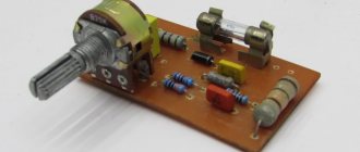
The charger for AA batteries is a device that generates direct current, charging up to 3 A/h. During production, the most common, even classic, scheme was used, which you see below. The basis, in this case, is the transistor VT1.
The voltage on this transistor is indicated by a red LED VD5, which acts as an indicator when the device is connected to the network. Resistor R1 sets a certain power of currents passing through this LED, as a result of which the voltage in it fluctuates. The value of the collector current is formed by the resistance from R2 to R5, which are included in VT2 - the so-called “emitter circuit”. At the same time, by changing the resistance values, you can control the degree of charging. R2 is constantly connected to VT1, setting a constant current with a minimum value of 70 mA. To increase the charging power, it is necessary to connect the remaining resistors, i.e. R3,R4 and R5.
It is worth noting that
the charger functions only when the batteries are connected .
After connecting the device to the network, a certain voltage appears on resistor R2, which is transmitted to transistor VT2. Then, the current flows further, as a result of which the VD7 LED begins to burn intensely.
Do-it-yourself charger for AA batteries - a metalworker's guide
Today, there are quite a lot of different battery-powered devices. And it’s even more annoying when, at the most inopportune moment, our device stops working, because the batteries are simply dead, and their charge is not enough for the normal functioning of the device.
Buying new batteries every time is quite expensive, but trying to make a homemade device for charging finger batteries with your own hands is quite worth it.
Many craftsmen note that it is preferable to charge such batteries (AA or AAA) using direct current, because this mode is most beneficial in terms of safety for the batteries themselves .
In general, the transferred charge power from the network is about 1.2-1.6 times the capacity of the battery itself. For example, a nickel-cadmium battery with a capacity of 1A/h will be charged with a current of 1.6A/h.
Moreover, the lower the given power, the better for the charging process.
- 1 Manufacturing process
- 2 Charging from USB port
- 3 Conclusion
Features of chargers for AA batteries
Using ordinary batteries is unprofitable, since their service life is very limited. Therefore, it is more practical to use batteries.
Their advantage lies in repeated use, provided they are handled correctly. First of all, this is due to the conditions for their recharging.
Batteries, releasing accumulated energy to devices, periodically need to be charged. This is what battery chargers are for.
History of chargers
The discovery of galvanic electricity led to the creation of the first prototype of rechargeable batteries. In 1798, Italian physicist Alessandro Volta conducted an experiment involving placing copper and zinc plates connected in series in an acid solution.
He discovered that when current was passed through the plates after it was interrupted, a residual charge remained on them. Subsequently, Gotero, Marianini, and Becquerel became interested in these experiments.
But it was only in 1859 that Plante created the truly first battery..
His experiment was based on strips of lead with a piece of cloth sandwiched between them. He then rolled the strips and immersed them in acidified water.
Further development led to the fact that when the plates were coated with lead oxides, the formation of the active layer improved.
In 1896, the American company National Carbon Company (NCC) was the first in the world to begin producing batteries. Today it is known as Energizer. Early in 1901, scientist Thomas Edison patented a nickel-cadmium type of battery.
At the same time, Waldmar Jungner was developing a nickel-iron type called an alkaline battery. Alkaline batteries are used in transport and power plants.
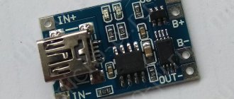
Charging from USB port
You can make a charger for nickel-cadmium batteries based on a regular USB port . At the same time, they will be charged with a current of approximately 100 mA. The scheme, in this case, will be as follows:
At the moment, there are quite a lot of different chargers sold in stores, but their cost can be quite high. Considering that the main point of various homemade products is precisely to save money, self-assembly is even more advisable in this case.
This circuit can be modified by adding an additional circuit to charge a pair of AA batteries. Here's what we ended up with:
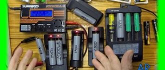
To make it more clear, here are the components that were used during the assembly process:
It is clear that we cannot do without basic tools, so before starting assembly you need to make sure that you have everything you need:
- soldering iron;
- solder;
- flux;
- tester;
- tweezers;
- various screwdrivers and knife.
Interesting material about making it yourself, we recommend viewing it
A tester is necessary to check the performance of our radio components. To do this, you need to compare their resistance, and then check it with the nominal value.
For assembly we will also need a case and a battery compartment. The latter can be taken from the children's Tetris simulator, and the body can be made from a regular plastic case (6.5cm/4.5cm/2cm).
We attach the battery compartment to the case using screws. The board from the Dandy console, which needs to be cut out, is perfect as a basis for the circuit. We remove all unnecessary components, leaving only the power socket. The next step is to solder all the parts based on our diagram.
The power cord for the device can be taken from a regular computer mouse cord with a USB input, as well as part of the power cord with a plug. When soldering, polarity must be strictly observed, i.e. solder plus to plus, etc. We connect the cord to USB, checking the voltage supplied to the plug. The tester should show 5V.
Construction and details
The charge-discharge device is mounted on a printed circuit board made of single-sided foil fiberglass laminate measuring 60x45 mm and placed in a plastic case. Due to the simplicity of the circuit, the device can be assembled on a breadboard or even mounted.
The PCB is designed for two channels and its drawing is provided. Element labeling is shown for only one channel, since the second channel is identical.
The following figure shows the location of parts on the board, as well as their markings according to the circuit diagram.
Battery compartments, LED and incandescent lamps, as well as switches and push-button switches are located on the outer part of the housing. The battery compartments are first glued to the case with glue, and then additionally secured with screws. Screws are used with countersunk heads.
The installation of battery compartments and switches is carried out by hinged mounting directly inside the case. Push-button switches are located at the rear of the housing and are connected to the printed circuit board by a flexible wire.
The device uses resistors with a power of 0.125 W. Resistor R2 is a multi-turn trimmer of any type. Instead of transistors KT315B (VT1, VT2) and KT814B (VT3), you can use any with similar parameters. KT814 transistors are equipped with heat sinks.
We can replace the KT502 (VT4) transistor with any silicon one with a maximum collector current of at least 150 mA. The KT3102G (VT5) transistor was selected with an increased current coefficient and can be replaced with any one with similar parameters.
The device is connected to the power supply using a regular USB cable. The connector that is used to connect to the phone is cut off and the red and black wires are used to supply power. The red vein is a plus, and the black vein is a minus.
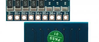
Diagram of a device for charging batteries AG0 - AG13
Instead of KD102B diodes, as you can see, there are KD105B diodes - everything works. I tried resistor values slightly different from those recommended and got a different maximum charge current at the output, from 2.5 to 10 mA. A charger with variable current will allow you to charge more efficiently the entire range of existing “watch” batteries, from format AG0 to AG13. So, in its final form, the memory circuit began to look like this.
Is it worth making such a charger?
This solution has its advantages:
- light weight;
- ease of manufacture;
- low cost;
- compactness.
But among the minuses, it is worth highlighting problems when charging from a generator and difficulties in operation at low temperatures. Also, the charger has low reliability and may not work at the most crucial moment. However, using it as a backup charger is a good option.
Now you know why you needed to study physics at school. Everyone can try to make a charger for lithium batteries with their own hands. This is not only saving money, but also new knowledge!
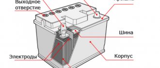
Why do you need a battery?
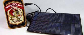
A universal battery will come in handy when traveling. You won't need to carry all your chargers with you. You can make a battery that will meet all your needs in terms of size and ease of use.
You can also make your own automatic battery charger, which will come in handy in the winter. Even if the garage or parking lot is heated, the battery still lacks heat. So it explodes quickly.
You can replenish its operating reserve during breaks using a homemade charger, and then you can safely travel long distances even in the most severe weather conditions.