Transistors KT117
KT117 is a special semiconductor device, the so-called unijunction transistor . KT117 is designed to work in generators as a low-power switch. A unijunction transistor does not have a collector, but has an emitter and two bases - 1 and 2.
The circuit equivalent to the KT117 unijunction transistor looks like this:
And the circuit of a sound generator assembled on KT117 may look like this:
The circuit turns out to be much simpler, since one KT117 replaces two conventional bipolar transistors here.
Main disadvantages
We are talking about the lack of electronic protection that could withstand a short circuit, overload, or polarity reversal. The fuse takes on part of the role of protection. But this is not the most convenient solution.
If you have the desire and experience, then you can separately assemble a protective circuit and connect it to a ready-made thyristor charger.
The second disadvantage is the galvanic connection of the tuning unit to the network. This drawback can be eliminated by using an adjusting resistance with a plastic axis.
Another disadvantage is the need to install cooling radiators. The best solution would be a finned radiator made of aluminum. The problem is partially solved. To do this, use a circuit that activates an adjustment module in the winding of the supply transformer.
In fact, assembling a thyristor charger is quite simple. But without certain skills and knowledge, taking on such work, as well as conducting experiments at home, is strongly not recommended.
How do you feel about homemade battery chargers? Has anyone assembled a charger using thyristors? Is it worth doing such homemade products?
Parameters of a unijunction transistor.
The maximum emitter current for KT117A, KT117B, KT117V, KT117G is 30mA.
The voltage between the bases - for all KT117 - is 30V.
The voltage between base 2 and emitter - for all KT117 - is 30V.
The maximum power dissipation for all KT117s is 300 mW.
Interbase resistance:
For KT117A,B - from 4 to 9 kOhm. For KT117V,G - from 8 to 12 kOhm.
The maximum operating frequency for all KT117s is 200 kHz.
Transfer coefficient - the ratio of the switching voltage to the voltage between the bases: For KT117A - from 0.5 to 0.7 For KT117B - from 0.65 to 0.9 For KT117V - from 0.5 to 0.7 For KT117G - from 0.65 up to 0.9
The transistor housing is plastic or metal-glass. Alphanumeric markings.
Foreign analogues of KT117A (B, V, D) - 2N6027, 2N6028.
Required Components
To make a homemade thyristor battery charger, you will need to collect all the necessary elements for assembly.
In the presented embodiment, an electrolytic type capacitor is used. It can withstand a voltage of at least 63 V.
Resistors, of which 6 are required, must have a power of 0.25 W. Another resistor is needed for 2 W.
Diodes for a rectifier must pass a current of no more than 10 A, and also withstand a reverse voltage of up to 50 V. The VD2 pulse diode used will withstand a similar voltage.
The following can be used as transistors:
- KT3107;
- KT502;
- KT361;
- KT503;
- KT315;
- KT3102.
The necessary components and analogues for them include:
- rectifier unit type KTs 402, 405 with any index;
- zener diodes KS 525, KS 518 or KS 522;
- transistor KT 117 with the letters B, V and G;
- diode bridge at the output, rated for 10 A (from D242 to D247).
Of course, this is far from the only available scheme. But this is one of the simplest options for making a homemade thyristor charger.
The operating principle of a unijunction transistor.
So, any unijunction transistor contains one pn junction, which is generally clear - from its name.
If there is only one transition, where does it have three electrodes, and how does it even work? On a semiconductor crystal of uniform conductivity, at a certain distance from each other, there are ohmic contacts - Base1(B1) and Base2(B2). Between them there is a pn junction region - a contact with a semiconductor of opposite conductivity, the ohmic contact of which is the emitter. Typically, the operating principle of a unijunction transistor is considered using a simple equivalent circuit.
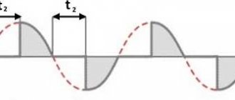
R1 and R2 here are the resistances between terminals B1 and B2, and V1 is the emitter pn junction. According to this circuit, current will flow through R1 and R2, and the voltage drop across R1 will bias the diode in the opposite direction. Thus, the diode will be closed until a forward voltage greater than the voltage drop across R1 is applied to the emitter. As soon as such voltage is applied, the diode opens and begins to pass current in the forward direction. In this case, the resistance R1 decreases even more - the drop voltage decreases. An avalanche-like process of opening the transistor occurs.
Everything with your own hands
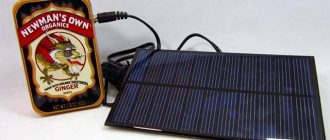
Hello. Today I will talk about a thyristor phase-pulse power regulator circuit that I have been using for a long time, which I will use as a charger for lead batteries. I already wrote about charging with a thyristor. This charger is much better. I will begin the description of the KU202 thyristor charger with the advantages: - The charger can easily withstand a current of up to 10A (depending on the thyristor, in this case KU202) - The charge current is pulsed, which, according to many radio enthusiasts, will help with the service life of the battery - The circuit consists of easily accessible parts, you can assembled almost from trash. The charger circuit is easily repeatable and even a beginner can assemble it, if only he knew how to solder - And the last advantage is that this circuit does not require any gadgets. The circuit is already equipped with everything necessary so that hackers do not burn out either the battery or the circuit. The charger circuit has short circuit protection, reverse polarity protection, and a charging voltage limiter. Limiting the charging voltage makes it possible not to monitor the end of charging, but to leave charging uncontrolled for a long time; the circuit itself will turn everything off
Scheme of a thyristor charger on KU202
Consider the charger circuit. On the left, on Q2Q3 transistors, there is a circuit of a thyristor phase-pulse power regulator; there is a lot of information on the Internet about what this is. The adjustment of the opening phase and, accordingly, the charging current is regulated by variable resistor R4. Transistors Q2Q3 are an analogue of a unijunction transistor, which can be replaced with KT117 to simplify the circuit. I use a power thyristor KU202, it is available here and is powerful enough to charge car batteries with sufficient current. By the way, the charging current is set to 1/10 of the capacity.
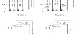
The right side of the diagram is battery protection. Transistor Q1Q4 contains overvoltage protection, short circuit protection and polarity reversal protection. The circuit turns on only when a battery is connected to the charging output. Current flows through the divider R3R6, opening transistor Q1 and energizing the phase-pulse current regulator. Reverse polarity protection works like this. When the terminals are not connected correctly, the current flowing through the same divider turns off the transistor, so no current flows to the power regulator. The charging cut-off device works quite simply, when the end of charging voltage reaches 14.4V, the voltage on the divider R8R11 becomes sufficient to break down the zener diode, transistor Q4 opens, closing Q1. And the most important thing in the circuit is the transformer. The circuit is powered by a transformer with a voltage of 18-25V. In my case, during testing, I powered the charger from a Regulated AC source. Printed circuit board of a thyristor charger for car batteries
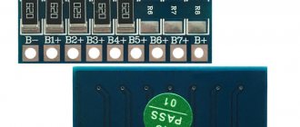
printed circuit board of a thyristor charger. How to make a printed circuit board with your own hands, you can see in the article How to make a printed circuit board.
At the output, the board has two LEDs to indicate battery connection. Green indicates a correctly connected battery, red indicates polarity is broken or polarity is reversed. It’s also a good idea to put a fuse on the output, just in case
Now about the tests. The circuit is soldered and assembled, the diode bridge and thyristor are installed on radiators, and the output wires are soldered.
The printed circuit board was used from old chargers and prepared for powerful resistors. But since I recalculated the values, now all resistors can be used at 0.25 W. I also used transistors like KT315 KT361, old but reliable. You can use KT3102 KT3107 KT814 KT815 KT816 KT817
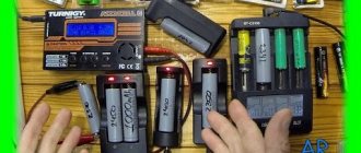
I’ll carry out the tests on a gel battery, I’m too lazy to remove a normal battery from the car! In this photo, I intentionally connected the charger incorrectly, but nothing happened other than the red LED lighting up. That's the way it should be
Now I connected it correctly and the current started flowing. The photo shows the minimum current readings, but you can make it smaller by increasing the rating of R4, say up to 33 kOhm. I left the minimum current at 2A, since there is no point in setting a lower current for a car battery
And here the maximum current is 8A. This indicator is regulated by resistor R2. The smaller the resistor, the higher the maximum current. But you shouldn’t chase the current, since the KU202 will not draw more than 10A, and a current of 10A is quite enough to charge a battery with a capacity of 120Ah.
The photo shows an almost charged battery and it’s time to make just one adjustment, this is to set the maximum voltage. To do this, you need to wait until the battery is charged to 14.4V and use the variable resistor R8 to set the torque so that the voltage does not rise higher.
And the entire circuit is assembled, charging, charging, and protection are working. I’ll stop there for now, this circuit was assembled to recalculate the resistor values, tell you about the principle of operation and what I will do with it next, I’ll tell you in the article about the starting charger, but for now that’s all.
Thanks to the reader, I was able to find out the author of the modification of the automatic shutdown circuit, the author is master144, and the discussion on the forum is here
Please do not write any more that the scheme is not working. Here is a video of the charger working
Do you want the same device? Write to me on my internal VKontakte email. And also subscribe to updates in the group, buttons at the top of the site, and you will always be aware of the latest updates From uv. Edward
Dear readers. The fact is that assembling my projects takes a lot of time, it’s unforgivable that I withhold a lot of money from the family budget and I won’t do it anymore. If you like what I’m doing here and want to continue, then I ask for your support. There will be support, there will be a lot of new things (drawings and diagrams are already there). You can support here
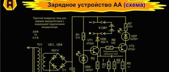
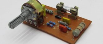
Scheme of a thyristor regulator based on a unijunction transistor.
The figure below shows a diagram of a thyristor regulator, with an incandescent lamp as a load.
R1 - 100 KOhm - variable, 0.5 W, any type. Resistors R2 - 3KOhm, R3 - 1KOhm, R4 - 100 Ohm, R5 - 30KOhm - MLT. VD1 - zener diode D814V VD2 - KD105B VD3 - KD202R VC1 - KU202N Capacitor C1 - 0.1MF 400V, any type. Transistor VT1 - KT117A Fuse 0.5 - 1.5 Ampere (depending on the power of the lamp.)
to Home Page
The use of any materials from this page is permitted provided there is a link to the “Electrical is Easy” website.
Self-production of simple chargers made on a thyristor
Any experienced car owner almost certainly has a charger (charger) in their garage or home. The highest quality type involves smooth regulation of current and output voltage. It will not be possible to do this with step switches; the best option is to use an electronic circuit, where the main role is played by a thyristor - a component that changes U and I in the load. However, store-bought devices are quite expensive, and if you have skills in working with a soldering iron and knowledge in the field of radio engineering, you can design a charger using a thyristor yourself, which will cost an order of magnitude cheaper.
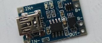
Schematic and printed circuit board of the SCR memory
The printed circuit board is drawn by hand with a marker. You can make the wiring yourself, for example based on this picture: