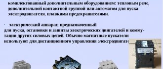
Electromagnetic contactors (starters)
We need to bring some order to the terminology.
Starters and contactors are often confused. To some they are the same thing, and some say that a contactor is just a big, powerful starter. But no one can really explain how powerful it is... Previously, during the times of the USSR, this was the case. Now starters that were produced or developed in those days are called starters (for example, PML, which is still produced in Ukraine), and new and foreign models are called contactors.
Electricians call the same devices starters, and sellers call them contactors. To be honest, I’m more used to talking about starters.
Safety and reliability
We set a goal: to create not only affordable, but also the most reliable and safe devices for solving a wide variety of household and industrial problems. It was important to achieve a balance of high quality and safety. This balance was achieved through a number of solutions we applied:
- — mechanical connection of contacts and additional mirror contacts for precise control of the starter state;
- — self-cleaning of contacts due to the use of additional contacts with corrugation and a sliding effect;
- — protection of terminals from direct contact with current-carrying elements;
- — continuous feedback from programmed controllers and microprocessors;
- — informing about the degree of wear of power contacts.
TeSys starters can withstand more than 1 million switching cycles, they are immune to shock and vibration, and do not make noise during operation. Schneider Electric equipment is indispensable equipment for any modern facility with high requirements for quality, reliability and efficiency at a reasonable price.
Main product advantages
The magnetic contactor from Schneider Electric has a number of advantages in comparison with analogues:
- — operating temperature range is above average – from -50 to +50 degrees Celsius;
- — extended range of rated current;
- — simplified installation thanks to special screwless clamps;
- — low noise during switching;
- — resistance to shock and vibration;
- — economical energy consumption;
- — the contactor additionally protects against voltage surges thanks to the built-in Transil diode;
- - increased durability and wear resistance, which is determined by the use of innovative developments.
Schneider Electric contactors: TeSys D and TeSys K series
TeSys D series
The series includes both reversible and non-reversible models, with different control circuit options. Suitable for all types of starters, connection - screw and spring terminals, terminal, cable with lugs, busbars or plug-in contacts. Each element is compatible with the manufacturer's latest patented technologies to ensure maximum engine protection, ease of installation and long-lasting installation. This type can be used as a contactor, motor starter, used in construction or organizing production infrastructure.
TeSys F series
The small dimensions of the devices in this series can provide a manifold increase in the efficiency of the working or operational process. This device with an automated switch will well complement the electronic relay contactor of this series, ensuring quick start-up and maximum engine protection. The TeSys F line equipment is safe and versatile in operation:
- — control circuits – alternating or direct current;
- — universal connection in various ways;
- — areas of application in addition to standard ones — control of engine operation;
- - any type in any operating conditions.
TeSys K series
Another compact modular contactor designed for three-phase motors. Significantly saves working space during installation and further operation; it can also be used as a starter contactor for electrical installations with low power consumption, susceptible to interference and voltage surges. Mounting method - on rails or screws, complete absence of noise during operation, control circuits - alternating or direct current, coils with reduced power consumption.
Areas of use:
- — residential or office premises;
- — industrial enterprises;
- — infrastructure.
TeSys B series
There is also a relay contactor of the TeSys B series. This is a rack vacuum contactor, available in four different models, the control circuit in this case is alternating current, rail mounted, designed to optimize the operation of motors of any type, capacitive and inductive connection circuits, circuits with active resistance .
This equipment is used in:
- — construction;
- - industry;
- — infrastructure;
- - in office and residential premises.
Electromagnetic starters PML
TU3420-091-05758109-2016. Electromagnetic starters of the PML series (hereinafter referred to as “starters”) are intended for use as switching
devices in electric drive control circuits, mainly in stationary installations, for remote starting by direct connection to the network, stopping and reversing three-phase asynchronous electric motors with a squirrel-cage rotor at voltages up to 660 V AC with a frequency of 50 and 60 Hz. The starters are equipped with thermal relays of the RTL TU3425-041 -05758109-2008 series, which provides protection of controlled electric motors from overloads of unacceptable duration and from currents arising when one of the phases is broken.
Optimal operating conditions, absence of noise and increased operational reliability are ensured by the use of special manufacturing technology for the magnetic contactor system. Wide possibilities for the layout of panels due to the possibility of mounting devices both vertically and turning to the right/left by 20°. Possibility of operation in harsh Russian conditions at ambient temperatures from -40°C to +55°C. Possibility of use in various operating conditions due to the enclosure with degree of protection IP54.
Symbol structure
Starter PML-Х1Х2Х3Х4Д-Х5А-Х6АС-(Х7А)-УХЛ3-Б-КЭАЗ
| Actuator | — Product group | |
| PML | — Series | |
| X1 | - A number indicating the size of the starter depending on the rated current: 1 - 10 A and 16 A, 2 - 25 A and 32 A, 3 - 40 A, 4 - 63 A, 5 - 100 A | |
| X2 | — A number indicating the intended use: 2 — irreversible | |
| X3 | — A number indicating the design according to the degree of protection: 2 — IP54 with “Start” and “Stop” buttons | |
| X4 | — A number indicating the number and design of auxiliary circuit contacts: | 40, 63, 100 |
| 0 | 1 "z" | 1 "z" + 1 "r" |
| 1 | 1 "r" |
An example of writing the designation of a starter with a rated current of 10 A, wear resistance version B, irreversible, degree of protection IP54, with 1 “z” auxiliary contact, with a switching coil for voltage 220 V with a frequency of 50 Hz, with a relay current setting range (7-10 A ) when ordering it and in the documentation of another product: Starter PML-1220-10A-220AS-(7-10 A)-UHL3-B-KEAZ
Starter PML-Х1Х2Х3Х4Д-Х5А-Х6АС-(Х7А)-УХЛ2-Б-КЭАЗ
| Actuator | — Product group | |
| PML | — Series | |
| X1 | - A number indicating the size of the starter depending on the rated current: 1 - 10 A and 16 A, 2 - 25 A, 3 - 40 A, 4 - 63 A | |
| X2 | — A number indicating the intended design: 2 — non-reversible, 6 — reversible with electrical and mechanical interlocking, 7 — star-delta | |
| X3 | — Execution by the presence of buttons: 1 — with a “Relay” button, 2 — with “Start” and “Stop” buttons, 3 — with “Start” “Stop” buttons and a signal lamp (manufactured only for voltages 127, 220 and 380 V , 50 Hz) | |
| X4 | — Design according to the number and purpose of auxiliary circuit contacts: | 40, 63 |
| 0 | 1 "z" | 1 "z" + 1 "r" |
| 1 | 1 "z" + 2 "r" |
An example of writing the designation of a starter for a rated current of 10 A, wear resistance version B, irreversible, degree of protection IP54, with “Start”, “Stop” buttons and a signal lamp, with 1 “z” auxiliary contact, with a switching coil for a voltage of 220 V frequency 50 Hz, with the relay current setting range (7-10 A) when ordering it and in the documentation of another product: Starter PML-1230-10A-220AS-(7-10a)-UHL2-B-KEAZ
Assortment of PML starters
Accessories for PML contactors and starters
Specifications
| Parameter name | Parameter designation | |||||
| Series | PML-1210 PML-1230 | PML-1611 PML-1621 PML-1631 | PML-1210D PML-1230D | PML-1611D PML-1621D PML-1631D | PML-2210 PML-2230 | PML-2611 PML-2621 PML-2631 |
| Type of main circuit current | variable | |||||
| Rated current, A | 10 | 16 | 25 | |||
| Motor power (AC-3) at 380 V 50 Hz, kW | 4,0 | 7,5 | 11 | |||
| Auxiliary contacts “z” - normally open “r” - normally open | 1 "z" | 1 "z" + 2 "r" | 1 "z" | 1 "z" + 2 "r" | 1 "z" | 1 "z" + 2 "r" |
| Execution | irreversible | reverse | irreversible | reverse | irreversible | reverse |
| Type of climate control | UHL2 | |||||
| Degree of protection | IP54 | |||||
| Design for switching wear resistance, million cycles (AS-3) | B-1.5 | B-1.0 | ||||
| Design for mechanical wear resistance, million cycles | B-10 | |||||
| Maximum switching frequency without load/with load, switchings per hour (AC-3) | 3600/2400 | 3600/1200 | ||||
| Rated operating current, A (AC-3) up to 380 V | 10 | 16 | 23 | |||
| Rated operating current, A (AC-3) at 660 V | 5 | 10 | 15 | |||
| Rated operating current, A (AS-1) | 20 | 32 | 40 | |||
| Rated operating current, A (AC-4) up to 380 V | 3,5 | 7,7 | 8,5 | |||
| Rated operating current, A (AC-4) at 660 V | 1,5 | 3,8 | 4,4 | |||
| Rated voltage of the main circuit, V | up to 660 | |||||
| Type of control circuit current | variable | |||||
| Rated control circuit voltage, V | 24, 36, 42, 48, 110, 120, 127*, 220*, 240, 380*, 400, 415, 440, 480, 660 | |||||
| Coil power consumption | ||||||
| switching on, VA | 70 | 110 | ||||
| retention, VA | 8 | 11 | ||||
| Rated insulation voltage, V | 660 | |||||
| Dimensions | ||||||
| Dimensions (HxWxD), mm | 160x87x116.5 | 280x123x143 | 185x101x134 | 280x123x143 | 185x101x134 | 280x123x143 |
| Installation, mm | 140 (2 M5 screws) | 260 (2 M5 screws) | 165 (2 M5 screws) | 260 (2 M5 screws) | 165 (2 M5 screws) | 260 (2 M5 screws) |
| Weight no more than, kg | 1,04 | 2,15 | 1,2 | 2,7 | 1,2 | 2,7 |
| 1,13 | 2,23 | 1,29 | 2,77 | 1,29 | 2,77 | |
| 2,27 | 2,85 | 2,85 | ||||
* Rated control circuit voltage for starters PML-1230, PML-1631, PML-1230D, PML-1631D, PML-2230, PML-2631
| Parameter name | Parameter designation | |||||
| Series | PML-3210 PML-3230 | PML-3210D PML-3220D PML-3230D | PML-3611D PML-3621D PML-3631D | PML-3610 PML-3620 PML-3630 | PML-4210 PML-4230 | PML-4610 PML-4620 PML-4630 |
| Type of main circuit current | variable | |||||
| Rated current, A | 40 | 63 | ||||
| Motor power (AC-3) at 380 V 50 Hz, kW | 18,5 | 30 | ||||
| Auxiliary contacts “z” - normally open “r” - normally open | 1 "z" + 1 "r" | 1 "z" | 1 "z" + 2 "r" | 1 "z" | 1 "z" + 1 "r" | 1 "z" |
| Execution | irreversible | reverse | irreversible | reverse | ||
| Type of climate control | UHL2 | |||||
| Degree of protection | IP54 | |||||
| Design for switching wear resistance, million cycles (AS-3) | B-1.0 | |||||
| Design according to M0V3U М U0, 1ГГ\1Л mechanical wear resistance, million cycles | B-10 | |||||
| Maximum switching frequency without load/with load, switchings per hour (AC-3) | 3600/1200 | |||||
| Rated operating current, A (AC-3) up to 380 V | 34 | 53 | ||||
| Rated operating current, A (AC-3) at 660 V | 21 | 43 | ||||
| Rated operating current, A (AS-1) | 60 | 80 | ||||
| Rated operating current, A (AC-4) up to 380 V | 18,5 | 28 | ||||
| Rated operating current, A (AC-4) at 660 V | 9 | 14 | ||||
| Rated voltage of the main circuit, V | up to 660 | |||||
| Type of control circuit current | variable | |||||
| Rated control circuit voltage, V | 24, 36, 42, 48, 110, 120, 127*, 220*, 240, 380*, 400, 415, 440, 480, 660 | |||||
| Coil power consumption | ||||||
| switching on, VA | 200 | |||||
| retention, VA | 20 | |||||
| Rated insulation voltage, V | 660 | |||||
| Dimensions | ||||||
| Dimensions (HxWxD), mm | 280x164x166 | 280x164x170 | 280x164x166 | 258x175x309 | 280x164x166 | 258x175x309 |
| Installation, mm | 260 (2 M5 screws) | 165x165 (4 M6 screws) | 260 (2 M5 screws) | 165x165 (4 M6 screws) | ||
| Weight no more than, kg | 3,1 | 2,4 | 3,24 | 6 | 3,11 | 6 |
| 3,15 | 2,42 | 3,24 | 6,08 | 3,16 | 6,08 | |
| 2,44 | 3,3 | 6,12 | 6,12 | |||
* Rated control circuit voltage for starters PML-3230, PML-3230D, PML-3630, PML-3631D, PML-4230, PML-4630
| Parameter name | Parameter designation | ||||||
| Series | PML-1220 | PML-1220D | PML-2220 | PML-2220D | PML-3220 | PML-4220 | PML-5220D |
| Type of main circuit current | variable | ||||||
| Rated current, A | 10 | 16 | 25 | 32 | 40 | 63 | 100 |
| Motor power (AC-3) at 380 V 50 Hz, kW | 4,0 | 7,5 | 11 | 15 | 18,5 | 30 | 45 |
| Auxiliary contacts “z” - normally open “r” - normally open | 1 "z" | 1 "z" + 1 "r" | |||||
| Execution | irreversible | ||||||
| Type of climate control | UHL3 | ||||||
| Degree of protection | IP54 | ||||||
| Execution according to switching HJnULUL 1 UHKUL. 1 Vlf NJIH CYCLIV (AC-3) | B-1.5 | B-1.0 | |||||
| MlPG|P1-1(=>1-1ы(=>PG1 V \\L IKJJ 1PSPIS 1 l\J mechanical wear resistance, million cycles | B-10 | B-5 | |||||
| Maximum switching frequency without load/with load, switchings per hour (AC-3) | 3600/2400 | 3600/1200 | 3600/750 | ||||
| Rated operating current, A (AC-3) up to 380 V | 10 | 16 | 23 | 28 | 34 | 53 | 86 |
| Rated operating current, A (AC-3) at 660 V | 5 | 10 | 15 | 18 | 21 | 43 | 56 |
| Rated operating current, A (AS-1) | 20 | 32 | 40 | 50 | 60 | 80 | 120 |
| Rated operating current, A (AC-4) up to 380 V | 3,5 | 7,7 | 8,5 | 12 | 18,5 | 28 | 44 |
| Rated operating current, A (AC-4) at 660 V | 1,5 | 3,8 | 4,4 | 7,5 | 9 | 14 | 21,3 |
| Rated voltage of the main circuit, V | up to 660 | ||||||
| Type of control circuit current | Variable | ||||||
| Rated control circuit voltage, V | 24, 36, 42, 48, 110, 120, 127, 220, 240, 380, 400, 415, 440, 480, 660 | ||||||
| Coil power consumption | |||||||
| switching on, VA | 70 | 110 | 200 | ||||
| retention, VA | 8 | 11 | 20 | ||||
| Rated insulation voltage, V | 660 | ||||||
| Dimensions | |||||||
| Dimensions (HxWxD), mm | 166x88x140 | 185x101x142 | 312x180x181 | ||||
| Installation, mm | 150 (2 M5 screws) | 165 (2 M5 screws) | 200x105 (4 M6 screws) | ||||
| Weight no more than, kg | 1,3 | 1,5 | 1,6 | 2,4 | 3,2 | 4,2 | |
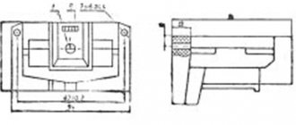
Overall and installation dimensions of PML starters of climatic version UHL3
Starters PML-1220, PML-1220D for rated currents of 10 and 16 A in a plastic shell
Starters PML-2220, PML-2220D for rated currents of 25 and 32 A in a plastic shell
Starters PML-3220, PML-4220, PML-5220D for rated currents of 40, 63 and 100 A in a metal shell
Overall and installation dimensions of climate control starters UHL2
Irreversible starters 1 and 2 sizes in a plastic shell
| Starter type | A | A1 | IN | L | H | H1 | H2 | Screw for fastening | Weight, kg |
| PML-1210 | 140 ± 0,4 | 46 ± 0,3 | 87 ± 1 | 160 ± 1 | 116,5 ± 1 | 18 ± 0,3 | M5 - 6g 2 screws | 1,04 | |
| PML-1220 | 1,04 | ||||||||
| PML-1230 | 124,5 ± 1 | 1,13 | |||||||
| PML-1210D | 165 ± 0,4 | 52 ± 0,3 | 101 ± 1 | 185 ± 1 | 134 ± 1 | 19 ± 0,3 | 1,20 | ||
| PML-1220D | 1,20 | ||||||||
| PML-1230D | 142 ± 1 | 1,29 | |||||||
| PML-2210 | 1,20 | ||||||||
| PML-2220 | 1,20 | ||||||||
| PML-2230 | 142 ± 1 | 1,29 |
Reversing starters 1 and 2 sizes in a plastic shell
| Starter type | A | A1 | B | B1 | H | H1 | H2 | Screw for fastening | Weight, kg |
| PML-1611 | 260 ± 0,7 | 46 ± 0,3 | 123± 1 | 280±1 | 130,5±1 | 18 ± 0,3 | M5 - 6g 2 screws | 2,15 | |
| PML-1621 | 2,23 | ||||||||
| PML-1631 | 136,5 ± 1 | 2,27 | |||||||
| PML-1611D | 52 ± 0,3 | 143±1 | 19 ± 0,3 | 2,70 | |||||
| PML-1621D | 2,77 | ||||||||
| PML-1631D | 149 ± 1 | 2,85 | |||||||
| PML-2611 | 149 ± 1 | 2,70 | |||||||
| PML-1621 | 2,77 | ||||||||
| PML-1631 | 2,85 |
Irreversible starters of 3 and 4 sizes in a shell, reversible starters of 3 sizes with reduced weight and dimensions in a plastic shell
| Starter type | A | A1 | IN | B1 | H | H1 | H2 | Screw for fastening | Weight, kg |
| PML-3210 | 34,5±0,5 | 60,5±0,5 | 31 ± 0,5 | 59 ± 0,5 | M5 - 6g 2 screws | 3,100 | |||
| PML-3220 | 3,130 | ||||||||
| PML-3230 | 170,5 ± 1 | 3,156 | |||||||
| PML-3210D | 2,400 | ||||||||
| PML-3220D | 2,420 | ||||||||
| PML-3230D | 170,5 ± 1 | 2,440 | |||||||
| PML-3611D | 3,200 | ||||||||
| PML-3621D | 3,240 | ||||||||
| PML-3631D | 170,5 ± 1 | 3,300 | |||||||
| PML-4210 | 42 ± 0,5 | 42 ± 0,5 | 44 ± 0,5 | 3,110 | |||||
| PML-4220 | 3,140 | ||||||||
| PML-4230 | 170,5 ± 1 | 3,160 | |||||||
| PML-1720 | 54 ± 0,5 | 30 ± 0,5 | 54 ± 0,5 | 54 ± 0,5 | 26 ± 0,5 | 56 ± 0,5 | 3,300 | ||
| PML-1720D | 3,300 |
Reversible starters 3 and 4 sizes in a metal shell
| Starter type | Screw for fastening | Weight, kg |
| PML-3610 | M5 - 6g 4 screws | 6,00 |
| PML-3620 | 6,08 | |
| PML-3630 | 6,12 | |
| PML-4610 | 6,00 | |
| PML-4620 | 6,08 | |
| PML-4630 | 6,12 |
Catalog PML starters (.pdf, 2.53 MB)
Operating manual for electromagnetic starters of the PML series (.pdf, 1.24MB)
What is the difference between a contactor and a starter?
In fact, a contactor is a device consisting only of an electromagnetic coil and contacts. When voltage is applied to the coil, the contacts close (or open). The contactor does not contain devices for protection, fixation, switching, indication, etc. A starter is a device that contains a contactor as the main component element. In addition, the starter usually contains a thermal relay for protection against overcurrent, START and STOP buttons, an indication, can be enclosed in a housing, and have a circuit breaker for short-circuit protection. In other words, the starter is used to start (turn on) various electricity consumers.
The starter can contain two contactors. This happens in cases where reverse engine control is used, or during a soft start, when a powerful engine is turned on first in a star circuit and then in a delta circuit.
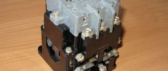
Disassembled starter PML-1220 0*2B. The contactor and thermal relay are visible.
Marking
The equipment marking or designation consists of 21 characters. They are designated in order:
- group,
- series,
- the size of the contactor by rated current,
- fulfillment as intended,
- performance according to the protective degree,
- design according to the contact number of the auxiliary electrical circuit,
- conditional number of rated connection current,
- the amount of voltage of the coil connected to the network,
- Climatic performance,
- wear resistance design,
- trademark.
Equipment marking
In general, a PML starter is a device consisting of a core and an armature. It is needed to remotely control three-phase motors. Supplied with surge suppressors. It has technical parameters indicated on the device body itself, in the form of markings.
Differences between a relay and a contactor
Relays differ from contactors only in design and purpose, and the difference between them is sometimes barely distinguishable.
Usually,
- The relay does not have arc chutes.
- The relay is housed in a sealed housing.
- The relay is designed for low current and purely resistive loads.
- The relay has switching contacts, which means normally open and closed.
- The relay is not designed to connect a reactive three-phase load.
- A relay can have from 1 to 6 equivalent contacts, and a contactor must have 3 power and (as an option) 1-2 low-current contacts.
- The relay does not have additional functions or contacts, and the contactor can be supplemented with attachments for various installations and purposes.
- The relay is mounted on the panel and can be easily replaced using just your hands. In order to replace the contactor, you need to de-energize the equipment and use a screwdriver.
Magnetic starters PML series
Description:
Electromagnetic starters of the PML series are used in stationary installations for remote starting by direct connection to the network, stopping and reversing three-phase asynchronous electric motors with a squirrel-cage rotor of alternating voltage 660V, frequency 50 and 60 Hz. If there are three-pole thermal relays of the RTT and RTL series, the starters can protect controlled electric motors from overloads of unacceptable duration and from currents that arise when one of the phases is broken. PML starters are compatible with control systems using microprocessor technology when the switching coil is bypassed with an interference suppression device or with thyristor control.
Used for remote starting by direct connection to the network and disconnecting three-phase asynchronous electric motors with a squirrel-cage rotor. Additional functions: reversing, in the presence of thermal relays - protection of motors from overloads of unacceptable duration, including those that occur when one of the phases fails, or a change in the switching circuit of the Y/A windings.
Structure of the symbol for magnetic starters of the PML series
Possible designations of magnetic starters of the PML series
The size of PML starters depending on the rated current: 1 -10A; 2 -25A; 3 -40A; 4 -63A;
Purpose and presence of a thermal relay for PML starters: 1 - non-reversible without a thermal relay; 2—irreversible with thermal relay; 5—reversing starter without thermal relay with electrical and mechanical interlocks; 6—reversing starter with thermal relay with electrical and mechanical interlocks; 7 — star-delta starter;
Protection level and presence of buttons: 0—IP00 without buttons; 1—IP54 without buttons; 2—IP54 with P+S buttons; 3 —IP54 with buttons P+S+signal lamp;
Main technical characteristics of magnetic starters of the PML series Table 1.6.7
| Starter characteristics | X100 | X110 | X210 | X220 | X230 |
| Rated current value, A | 10-63 | ||||
| Design and availability of thermal relay | irreversible without thermostat | irreversible with thermostat | |||
| Level of protection and presence of buttons | IP00 | IP54 without buttons | IP54 without buttons | IP54 with [Start] [Stop] buttons | IP54 with [Start] [Stop] buttons and warning light |
Overall dimensions (mm) Table 1.6.8
| Name | V, mm | L, mm | N, mm |
| PML 1100, PML 1101 | 64 | 78 | 74* |
| PML 1110, PML 1111 | 103 | 180 | 125 |
| PML 1210, PML 1220 | 87 | 160 | 116 |
| PML 1501 | 103 | 78 | 78* |
| PML 1611, PML 1621 | 123 | 280 | 130 |
| PML 2100, PML 2101 | 76 | 88 | 89* |
| PML 2210, PML 2220 | 142 | 270 | 136 |
| PML 2230 | 101 | 185 | 142 |
| PML 2501 | 128 | 100 | 149* |
| PML 2611, PML 2621 | 123 | 280 | 143 |
| PML 3100 | 75 | 127 | 107* |
| PML 3110, PML 3120 | 164 | 280 | 166 |
| PML 3220. PML 3230 | 164 | 280 | 166 |
| PML 3500 | 165 | 127 | 137* |
| PML 3610, PML 3620 | 258 | 309 | 171 |
| PML 4100 | 75 | 127 | 107* |
| PML 4110, PML 4210 | 164 | 280 | 166 |
| PML 4220, PML 4230 | 164 | 280 | 166 |
| PML 4500 | 165 | 126 | 137* |
| PML 4610, PML 4620 | 258 | 309 | 171 |
You can obtain additional information on PML starters by calling the phone number listed at the top of the page.
Installation of starters
Electromagnetic contactors are installed in two ways: on a DIN rail or using durable galvanized bolts.
Mounting equipment on a DIN rail
The contactors are mounted on a DIN rail thanks to the presence of a special groove with a retractable stopper on the back of the base. In order to fix the starter, the groove stopper is pulled out to the end, the device is put on a metal or plastic rail 35 mm wide, after which the stopper is returned to its original position. A starter secured in this way can, if necessary, be quickly dismantled and replaced with a new one.
DIN rail
Bolting
The contactor is secured using bolts as follows:
- Several holes are drilled in the panel on which the device is planned to be mounted;
- Using a tap, an internal thread of the required diameter is cut into the drilled holes;
- The bolts are inserted into the holes on the starter body and screwed into the cut threads on the panel.
Compared to a DIN rail, this installation method is more reliable, but it also requires significantly more time and effort.
Options
The main parameters of such devices include:
- Switching wear resistance is a characteristic indicating the maximum number of on/off cycles the device can withstand without repairing or replacing contacts;
- Number and type of contacts;
- Rated current for which the device contacts are designed;
- Voltage supplied to the control coil;
- Degree of protection (IP) from moisture and dust;
- Availability of control buttons, signal lamp;
- Availability of reverse function and built-in thermal relay;
- Dimensions and weight;
- Type of fastening (on DIN rail, using screws or bolts).
On a note. The main characteristics of the starter can be found by deciphering its markings.
Purpose and features of small-sized contactors
Frequent changes in current in electrical networks when turning electrical equipment on and off leads to emergency situations. To prevent them, a KMI contactor is used, which operates remotely under the control of weak electric currents. The name stands for small contactor. The device is also known as a KME contactor, that is, electromagnetic. It closes and opens electrical circuits that are in normal mode. These devices do not protect against short circuits, like automatic machines, but only carry out a combination of rated currents on different lines.
The small-sized KMI contactor is designed for a current load in the range of 9-95 A. Basically, these are asynchronous electric motors with a squirrel-cage rotor, as well as various types of loads with low inductance. Devices operating with a current load of up to 40 A are equipped with one group of make-break contacts. For currents above 40 A, two separate contact groups are installed - making and breaking.
These devices switch three-phase capacitor banks, as well as primary windings in three-phase low-voltage transformers. Exactly the same functions are performed by the small-sized KME - electromagnetic contactor.
Equipment of this type has undoubted advantages:
- The KMI - IEK series is produced in a wide range, significantly exceeding the number of analogues on the domestic market of electrical appliances.
- Together with contactors there are a large number of additional devices - contact attachments, electrothermal relays, time delay attachments and other useful equipment. They protect the electric motor from maximum current overloads, phase distortions and asymmetry, prolonged starting and rotor jamming.
- All KMI-IEK devices can be easily installed on a DIN rail with a width of 35 mm, unlike domestic products, for which such fasteners are installed only upon request.
- KMI-IEK devices allow reverse operation using a special locking mechanism.
- The design of the cover allows you to install additional contacts using a special attachment.
Connecting starters
The process of connecting the PML starter includes attaching the operating and supply circuit wires to the power contacts, connecting the power to the control coil.
Coil connection
To connect the control coil, wires from the button are connected to its two terminals. The wires used are the same as for installing the operating load circuit.
Additional devices
Additional devices used in conjunction with electromagnetic contactors of the PML series include the following:
- Thermal relays – protect the load connected to the contactor from high currents;
- Buttons – used to turn on the contactor;
- Contact extension attachments – used to increase the number of contacts in the operating circuit;
- Time delay relay – allows you to set the contact activation delay time.
When working with this type of electrical switching devices, experts advise not to disassemble and repair them yourself without special skills and experience. Technical inspection, disassembly and repair of starters should only be performed by qualified electricians.
Conditions for installation and placement of PMA starters.
Installation is carried out on a vertical surface using mounting screws, with an inclination of no more than 15 degrees. The altitude above sea level is not more than 2000 meters (when placed at an altitude from 2000 meters to 4300 meters, the rated current of the starter is reduced by 10%). PMA starters are installed in rooms with a non-explosive environment in which there are no aggressive gases in concentrations that can lead to destruction of the structure.
Design features.
Depending on the values, starters have different designs. For example, contactors of 3rd magnitude starters have a linear W-shaped magnetic system. This system consists of an armature and a core, which are housed in a plastic housing. Contactors of starters of the 4th, 5th, 6th magnitude have a different magnetic system - a forward-running U-shaped magnetic system. If a thermal relay is used together with the starter, then it is attached to the starter using a special square.
Decoding
- PMA series designation
- 3 - designation of rated current 40A
- Designation of starters based on the presence of a thermal relay and reversing design: 1 starter without a non-reversing relay
- 2 irreversible types with thermal relay
- 3 without thermal relay, reversible type
- 4 with reversible thermal relay
- 0 IP 00 without protective shell
Overall and installation dimensions
PME
| Figure 1. PME series irreversible starter with relay | Figure 2. PME series reversible starter with relay | ||||||
| Figure 3. PME series starter in a protective housing | |||||||
| Starter type | Drawing | L, mm | H, mm | B1, mm | B2, mm | A1, mm | A2, mm |
| PME-211 UHL4 V | 1 | 89 | 116 | 93 | — | 75 | 75 |
| PME-212 UHL4 V | 170 | ||||||
| PME-213 UHL4 V | 2 | 200 | 130 | 130 | — | 170 | 100 |
| PME-214 UHL4 V | 170 | ||||||
| PME-221 U3 V | 3 | 150 | 154 | 222 | — | 100 | 150 |
| PME-222 U3 V | — |
PML starters
The electromagnetic starter of the PML series is a modified contactor, the universal fastening of which allows it to be mounted either on a DIN rail or using bolts.
PML starters are widely used in stationary installations for remote starting, stopping and reversing three-phase asynchronous electric motors with a squirrel-cage rotor. It is possible to operate PML starters in other control and power distribution systems.
It is possible to install thermal protection, which allows the starters to protect electric motors from overloads and from currents arising from phase failure.
At the request of consumers, starters are equipped with an additional contact group (block contacts), used in control circuits, as well as a start/stop button. Depending on the design, the block contact may contain one or more normally open and/or one or more normally closed contacts. In addition, reversible assembly of starters is carried out, both with and without a thermal relay.
The reversible design of PML starters reverses three-phase motors by changing the order of the phases and consists of two starters mounted and interlocked with a mechanical and/or electrical interlock, which eliminates the possibility of simultaneous activation of the starters.
Structure of the symbol for starters of the PML-Х1Х2Х3Х4-А Х5 series:
- PML - type of magnetic starter;
- GOSTO - trademark;
- X1 is the value of the rated current of the starter (where “1” is 10A, 12A, “2” is 25A, “3” is 32A, 40A, “4” is 65A, “5” is 95A);
- X2 - design of the starter for its intended purpose and the presence of a thermal relay (where “1” is non-reversible, without a thermal relay; “2” is non-reversible, with a thermal relay; “4” is reversible, with a relay; “5” is reversible with electric and mechanical interlocking, without thermal relay; “6” - reversible, with thermal relay mechanical interlocking; (electrical interlocking upon request));
- X3 - version of the starter according to the degree of protection and the presence of buttons (where “0” - IP00; “1” - IP54, in a housing, without buttons; “2” - IP54, in a housing, with “Start” and “Stop” buttons; “ 3"-IP54, in a housing, with "Start", "Stop" buttons and a signal lamp; "4"-IP40, in a housing, without buttons; "5"-IP20; "6"-IP40 with "Start" and “Stop”; “7” – IP40, with “Start”, “Stop” buttons and a warning light);
- X4 - version of the starter according to the number of contacts of the auxiliary circuit (where “0” - 1 “p” (for 12A-40A), 1 “z” + 1 “p” (for 63A-95A), additional contacts - installation of a contact attachment is allowed PCL (to be specified when ordering);
- A - series index;
- X5 - climatic version and placement category.
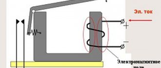
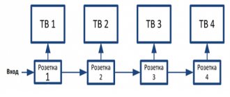
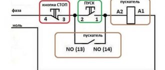
The figure shows a simplified diagram of turning on the engine using a starter. The switching element is the starter. The control circuit is assembled using Start and Stop buttons.
Selecting a starter depending on engine power:
| Mains voltage | Power of controlled motors, kW | |||||
| 220V | 3 | 5,5 | 7,5 | 18,5 | 30 | 40 |
| 380V | 4 | 11 | 11 | 30 | 45 | 75 |
| 660V | 3 | 11 | 18 | 33 | 55 | 100 |
| Starter size | 1 | 2 | 3 | 4 | 5 | 6 |
| Starter current | 10A | 25A | 32A | 63A | 100A | 160A |
Upon approval of the order, ANY EXECUTION of starters of the PML series is possible upon individual request (a combination of different nominal characteristics and additional components).
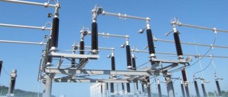
Areas of use
Among the leaders in the production of safety electrical equipment and automation equipment, Schneider Electric is deservedly considered one of the most reliable and progressive. Modular contactors are widely used in industrial production, trade and in everyday life.
This type of electrical equipment is most in demand for energy supply and installation:
- — ventilation and air conditioning systems;
- — lighting systems;
- — valves;
- — automatic gates, doors, etc.
All magnetic contactors can be divided into two categories, differing in their design features and capabilities:
- - reversible;
- - irreversible.
Structural elements
Each KMI contactor is equipped with a coil or electromagnet, which forms the basis of the device. This component is powered over a wide voltage range - 12-380 volts. Before connecting, you need to accurately set the operating current of the electromagnet, indicated in the passport or on the side of the coil body.
The next important design element is the core. It is a prefabricated structure with metal plates impregnated with varnish. The core consists of fixed and moving parts. The first part is used to accommodate the coil, and the other part - the movable one - is intended to accommodate the movable contacts. The fixed contacts are secured using screws to the plastic body of the device. Movable – attached to the core with a special insulating holder. Short-circuited aluminum rings are pressed into the pole tips of the stationary part, eliminating the effect of detonation.
The contact area of the contact solders in different IEC designs may differ. It depends on the operating current of the power circuits, which can be passed by the contactor. In this regard, each type of device has its own value - first, second, third, etc. Most of them are equipped with four contact pairs: three are intended for the power circuit, and one is additional and performs various functions. It blocks the control circuit, turns on a sound or color alarm, and partially provides automatic relay protection for the control of electrical installations.
The conductors are connected using special connecting contacts. They have an oval shape, which increases the reliability of fixation. For small wires, hardened disc washers are used, and for large conductors, a clamping clamp is provided. Notches on the contacts further increase the reliability of fixation, increase the contact area and reduce heating of the wires.
When power is applied to the coil, it results in an electromagnetic effect. Under its influence, the metal cylinder begins to move upward, after which the contact closes. The circuit supplying power to the coil is considered the control circuit, and the voltage in it is quite low, within 24 volts. The other circuit that closes the contact is a power circuit, since a current with a voltage of up to 660 volts passes through it. In the absence of power supply, the metal core returns to its original position under the action of a spring, and the circuit is open.
Design
Structurally, the electromagnetic contactor consists of two main blocks:
- Bottom (base) - this block consists of a cover, inside of which there is an W-shaped fixed magnetic circuit with a control coil in the central part. The number of turns and dimensions of the control coil depend on the voltage applied to it. Thus, in Soviet and modern models of these devices, coils designed for voltages from 24 to 380 V can be installed.
- Upper (contact group) - this block includes two types of contacts: movable and fixed. Spring-loaded movable contacts are located on a traverse with a fixed magnetic circuit (core) having the same shape and dimensions as that installed in the base. In this case, the cores of the base and contact group, identical in shape and size, are located opposite each other.
Two groups of fixed contacts are located on both sides of the movable traverse and secured in special grooves with screws. One group of such contacts is supplied with power cables that are under the voltage required to power the load. The second group of contacts is connected to the operating circuit - the cables that power the load.
Since sparking often occurs when connecting relay contacts, the entire upper part of the device is covered with a special cover that acts as a spark arrester.
PML contactor design
Between the upper and lower blocks there is a return coil or leaf spring.
On a note. For safety and more convenient control of the device, it is often placed in a sealed case with two buttons: “Start” and “Stop”. Some models often have a third button – “Reverse”.
Operating principle
This multi-contact electromagnetic relay works as follows:
- Using a button, an electric current with a specified voltage is supplied to the control coil;
- The current passing through the turns of the coil leads to magnetization of the W-shaped fixed core of the base;
- The magnetized lower fixed core attracts the magnetic circuit located on the movable cross-arm, compressing the elastic return spring;
- As a result of the attraction of the traverse core to the base magnetic circuit, it is closed by the spring-loaded fixed power contacts;
- As a result of the pairwise closure of the movable contacts of the traverse of the fixed power contacts, the load is switched on.
Magnetic starter
Disconnection of the starter and, accordingly, the load connected to it occurs when the supply of electric current to the control coil is stopped: the lower core is demagnetized and ceases to attract the upper one, as a result of which the traverse with contacts under the action of an expanding elastic spring disconnects the power contacts.
On a note. Under normal conditions, a working starter makes clicking sounds of the same duration when turned on and off. If the device makes different sounds, then there may be various malfunctions of its internal components.
Technical characteristics and types of KMI
The standard KMI contactor is an alternating current electromagnetic device that provides switching of electrical installations and equipment with power circuits.
Each model has the symbol KMI-Х-ХХ-Х-Х, which is deciphered as follows:
- The first character X means operating current limits, which are 1-9, 12, 12 A, 2-25, 32 A, 3-40, 50 A, 4-65, 80, 95 A and correspond to specific groups of devices.
- The second symbol XX corresponds to the rated current of category AC-3 and means several groups of small-sized starters. 1st group - 9, 12 and 18 A, 2nd group - 25 and 32 A, 3rd group - 40 and 50 A, 4th group - 65, 80 and 95 A.
- The third character X indicates the specific configuration of the contactor. For example, the number 1 corresponds to a device without a shell and without reverse.
- The fourth X character indicates the number of additional contacts. The number 0 is 1 normally open contact, the number 1 is 1 normally closed contact. The number 2 corresponds to the 1st make and 1st break contact.
The main parameters and technical characteristics include the following:
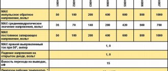
- The rated operating voltage is 230, 400 and 660 volts.
- The rated insulation voltage is 660 V.
- The rated pulse voltage is 6 kV.
- Rated operating current – 9-95 A.
- The value of the conventional thermal current is from 25 to 125 A.
- Indicators of maximum short-term load for less than 1 s for different devices range from 162 to 1710 A.
There are other device characteristics specified in the technical documentation that should be taken into account when choosing a product.
The manufacturer IEK produces a wide range of devices with different parameters and the possibility of use in various electrical circuits. Among them, three main groups can be noted:
- Small-sized AC IEC devices 9-95 A. Used for remote control of various industrial electrical installations, in lighting systems, etc.
- The contactor is a small-sized KMI with a thermal lever in its design. It is placed in a metal or plastic case and is used for switching three-phase motors operating with voltages up to 400 volts. If any phase is broken and overloads occur, this device is triggered and protects the circuit.
- KMI contactor, which has a coil that controls direct current. Used in automatic transfer systems, at power plants and distribution points, in electrical networks of railways and subways. There is no inrush operating current in the control coil.
PML starter. Technical description.
The PML starter is used in stationary installations for remote starting by direct connection to the network, stopping and reversing three-phase asynchronous electric motors with a squirrel-cage rotor of alternating voltage up to 380V, frequency 50 and 60 Hz.
In the presence of three-pole thermal relays of the RTL series, PML starters protect controlled electric motors from overloads of unacceptable duration and from currents arising when one of the phases is broken.
Structure of the symbol for starters of the PML-Х1Х2Х3Х4-А Х5 series:
- PML - type of magnetic starter;
- GOSTO - trademark;
- X1 is the value of the rated current of the starter (where “1” is 10A, 12A, “2” is 25A, “3” is 32A, 40A, “4” is 65A, “5” is 95A);
- X2 - design of the starter for its intended purpose and the presence of a thermal relay (where “1” is non-reversible, without a thermal relay; “2” is non-reversible, with a thermal relay; “4” is reversible, with a relay; “5” is reversible with electric and mechanical interlocking, without thermal relay; “6” - reversible, with thermal relay mechanical interlocking; (electrical interlocking upon request));
- X3 - version of the starter according to the degree of protection and the presence of buttons (where “0” - IP00; “1” - IP54, in a housing, without buttons; “2” - IP54, in a housing, with “Start” and “Stop” buttons; “ 3"-IP54, in a housing, with "Start", "Stop" buttons and a signal lamp; "4"-IP40, in a housing, without buttons; "5"-IP20; "6"-IP40 with "Start" and “Stop”; “7” – IP40, with “Start”, “Stop” buttons and a warning light);
- X4 - version of the starter according to the number of contacts of the auxiliary circuit (where “0” - 1 “p” (for 12A-40A), 1 “z” + 1 “p” (for 63A-95A), additional contacts - installation of a contact attachment is allowed PCL (to be specified when ordering);
- A - series index;
- X5 - climatic version and placement category.
Technical characteristics of PML:
| Parameter name | Meaning |
| Rated current | 10A, 12A, 25A, 32A, 40A, 65A, 80A, 95A |
| Main circuit rated voltage | ~ current U up to 380V, 50-60 Hz |
| Control coil | 24V, 36V, 42V, 110V, 220V, 380V, 50-60Hz |
| Auxiliary contacts | depending on configuration |
| Thermal relay | depending on configuration |
| Reverse (reversing starter) | depending on configuration |
| Mounting method | screw, DIN rail |
| Operating mode | intermittent PV 40% |
| Degree of protection | — IP00, IP20 (open) — for installation in heated rooms on panels, in closed cabinets and other places protected from water, dust and foreign objects, - IP40 (in the shell) - for installation inside unheated rooms in which the environment does not contain a significant amount of dust and water does not enter the starter shell, — IP54 (sheathed) — for indoor and outdoor installations in places protected from direct exposure to solar radiation and precipitation |
| Climatic versions and placement category | U3 |
Appearance, overall, installation and connection dimensions of PML starters:
| Starter type | V, mm | C, mm | D, mm | E, mm | F, mm | G, mm | d, mm |
| PML-1100 | 80 | 75 | 45 | 34 | 48 | 54 | 5 |
| PML-2100 | 93 | 83 | 56 | 40 | 50 | 55 | 5 |
| PML-3100 | 100 | 83 | 56 | 40 | 50 | 55 | 5 |
| PML-4100 | 112 | 98 | 76 | 40 | 108 | — | 6 |
| PML-5100 | 120 | 122 | 86 | 40 | 108 | — | 6 |
Note: The manufacturer reserves the right to improve this product aimed at improving its quality and reliability.
Contactor capabilities
Three-pole electromagnetic AC contactors are the most popular. The principle of operation is simple: a certain voltage is transmitted to the coil from the power source, after which it begins to turn on and off power contacts at short intervals. This technology eliminates surges and uncontrolled increases in voltage, reduces the duration of the arc, and protects power contact blocks from premature failure even during intensive use.
Contactors are aimed at automating the switching of electrical circuits and at the safe control of asynchronous equipment. Thanks to proven components, it becomes possible to build an extensive automated control system and at the same time ensure maximum safety.
terms of Use
The electromagnetic starter is designed to operate at a temperature of +/-40 degrees Celsius, with a degree of environmental pollution of 3 points and at an altitude of no more than 2 thousand meters. Its normal operating position is to be mounted on a vertical plane using the terminals of the switching coil up and down with screws or by snapping a standard rail. Deviation from the top in any direction is acceptable.
Mandatory use with voltage limiter
The device may only be used in accordance with the instructions. Only in this case is it possible to achieve a positive effect from interacting with it and at the same time maintain its performance while protecting the controlled electric motor from overload and electric current that appears at the moment of a break in one phase.
You might be interested in Description of the Peltier element
Use according to instructions