In this article, the reader will find useful information on how to assemble a three-phase input distribution device (IDU) for a private home. All the information you read below is almost entirely based on articles by Yu.V. Kharechko from his books [1] and [2].
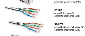
Below is an example of a three-phase input-distribution device for the electrical installation of an individual residential building (private house) with a ground floor, first floor and attic. The electrical installation of an individual residential building corresponds to the type of grounding of the TN-CS system. It is connected to the overhead power line with a four-core cable having three phase conductors and a PEN conductor. The division of the PEN conductor into a protective conductor (PE) and a neutral conductor (N) is made on the input terminal blocks of the ASU (see the circuit diagram of the ASU in Fig. 1).
Input distribution device (IDU). Types and application
The name input-distribution device (IDU) indicates that it is mounted at the input of electrical networks of several consumers, distributes electricity across them, and allows automatic power outage in the event of malfunctions and short circuits.
With the help of an ASU, it is convenient to disconnect the electrical circuit in the house during repair work, or for a period of prolonged inactivity of the electrical circuit. In multi-storey residential buildings, such an input system is installed in vestibules or stairwells. In small two-story houses, such an electricity input device is placed on the outside of the house. In factories, such devices are mounted in the workshop or on the outer wall of the production building. Typically, the input distribution device is used for alternating current voltage of 220 or 380 V.
Types of ASU
Electricity distribution and input devices are classified according to various criteria: the number of protective and other devices, size, current strength. Some samples have a special place for energy meters, and there are also devices that control the operation of lighting. Electrical circuit breakers located in the ASU housing serve for automatic emergency de-energization of circuits.
According to the purpose and characteristics of the ASU device, they are divided into the following types:
- Input systems responsible for receiving electricity.
- Distribution type, designed for distribution and accounting of data.
- Input and distribution systems that simultaneously perform the functions of the two previous types.
By current load on:
- 250 amp.
- 400 amp.
- 630 amp.
Design features
These devices differ significantly in size, since much depends on the power of the connected consumers. In turn, this indicator is related to the number of consumers who need electricity.
The input distribution device belongs to the group of electrical devices, which include various devices. The ASU not only receives energy, but also distributes it among objects. Each large residential building must have a separate ASU installed.
If the main facility consists of additional individual consumers, then additional ASUs are installed at each facility.
ASU equipment and devices are placed in metal cabinets, which consist of the following parts:
- The wires are connected to the copper busbars using a bolted connection. To increase the reliability of contact of power circuits, spring washers are additionally used. The phase bus must have holes for connecting consumer phase conductors. Working neutral conductors going to the consumer are connected to the neutral bus, which has similar holes.
- The input machine is used to connect the power cable. The parameters of the machine are determined in accordance with the power supply project.
- Fuses can be installed instead of an input circuit breaker and are intended for the same purposes. Their rating is also selected in accordance with the load size.
- The input circuit breaker protects the electrical wiring of the household network from excessive loads, short circuits, and also for performing power outages for network maintenance.
- Voltage limiters or arresters. They are installed after the input machine. If pulse overvoltages occur, the arrester is triggered. In this case, phase voltage is supplied to the protective bus, as a result of which the protection of the switchgear is triggered.
- A group of machines for individual networks. The main task of these machines is to distribute electricity among separate groups. Each group serves a separate room in the apartment, lighting and other various consumers requiring separate protection. If necessary, install protective shutdown devices. The machines are connected taking into account a uniform load for all phases. The number of machines in each phase is determined by the highest load of the connected networks.
- Wires and terminal blocks for making various connections. The wires must have the insulation color according to their intended purpose: phase - red wire, neutral wire - blue, ground - yellow-green. The ends of the wires must be marked. The phase bars must be painted in different colors. Conductors must have insulation suitable for 660 volts. At the point where the wires are introduced into the input distribution device, they are enclosed in bushings to ensure reliable insulation.
- Electricity consumption metering devices. Metering devices installed in these devices make it possible to control electricity consumption and the optimal distribution of loads in different circuits.
Operating principle
- The main power cable is inserted directly into the ASU input machine. The rated current of this machine is determined in advance. Its value is fixed in the technical specifications. The input machine protects the electrical wiring in the event of an emergency.
- This machine can forcefully turn off the power supply for network maintenance. There are ASU designs in which the input machine is replaced by a special disconnector or switch.
- The next elements installed behind the input machine are arresters. They are used to connect the protective bus and phase conductors. When powerful pulses occur, the arresters are triggered, which activates the protection of the input distribution device.
- The distribution of power supply finally occurs across groups of conductors, and is carried out by circuit breakers of different ratings. An additional protective measure is a residual current device.
Areas of application of ASU
The use of ASUs has its own characteristics depending on the places of their application. Let's consider the main features of using ASU.
Energy distribution in an apartment building with a TN-C system
TN-C is an outdated system, but it is actively used in old houses. This is a four-wire system consisting of three voltage phases and a combined neutral and working conductors (L1, L2, L3, PEN). In this PEN system, the conductor cannot be split and is delivered to the consumer in this form. It is also worth noting that quite often phase wires are given the names A, B, C.
As a result, with such a power supply system, with a single-phase connection, the consumer is connected with two wires (L, PEN), and with a three-phase connection with four (L1, L2, L3, PEN).
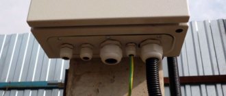
A power cable runs underground from the substation to the house. The cable enters the input box connected to the distribution board:
The risers laid vertically will extend from it. On each floor, floor panels will be connected to the risers, from which the apartments will be supplied with electricity.
Inputs can be made in various ways, this directly depends on the number of floors and size of the house, on the cable laying system (in the collector or in the ground). Why is that? Yes, because the load of a house with 100 apartments will be significantly lower than a house with 500 apartments. Moreover, the power supply requirements of, for example, a five-story building are relatively small - there are no elevators in the building and there is no need to install additional pumps to maintain water pressure, which cannot be said about a 30-story building where elevators and water supply pumps cannot be left without power.
It is for these reasons that not one, but two or more power supply cables with mutual redundancy can be installed in large houses. Distributing electrical energy between common building loads (elevators, entrance lighting, pumps) and apartments is a rather complex and time-consuming task. Distribution is carried out using complete electrical devices, the mounting methods, dimensions and installation locations of which are coordinated with the designs of the houses.
Let's look at options for connecting apartments to risers in apartment buildings with a TN-C system. The riser has four wires - three phases and one PEN conductor, designated in the diagram as A, B, C and PEN:
Between phases (A-B, C-B, C-A) the voltage will be 1.73 or more than between any of the phases and the neutral conductor (zero). From here we calculate the voltage between phase and neutral - 380/1.73 = 220 V. Two wires enter each of the apartments - phase and neutral. The current in both of these wires will be exactly the same.
They try to connect the load (in our case, apartments) evenly to different phases. In Figure a), out of six apartments, two are connected to each phase. Uniform connection makes it possible to reduce the neutral conductor current and avoid phase imbalance.
In old houses, combined electrical cabinets were sometimes used instead of floor panels. An example of such a cabinet is shown below:
This cabinet has compartments with separate doors. In one compartment there are signs with apartment numbers, switches and circuit breakers. In another there are meters, in the third there are low-current devices such as telephones, networks of television antennas, twisted pair cables for intercoms, the Internet and other devices.
In such a floor panel, each apartment has one switch and two automatic switches (the first for the general lighting line, and the second for plug sockets). Some versions of electrical cabinets may have a plug socket with a protective contact for connecting various machines (for example, cleaning machines).
Purpose
ASU, UVR or input switchgear is a set of various electricity metering devices, circuit breakers, fuses, etc. Depending on the size, several dozen different switches, transformers, and meters can be placed in it. There is also an IVRU - such a passport for a standard IVR means that it is an inventory one.
Photo - ASU with meters
The main difference between the modernized IVRU and the standard one is its increased degree of anti-vandal protection, the ability to be used in field conditions and at facilities under construction.
Photo - IVRU
The main purpose of the input switchgear is to supply the building or individual parts of residential and industrial premises with electrical energy. It consists of panels that are of one-way service type, i.e. they open only on one side. Depending on the design, there are single, two and three panels. Accordingly, these are VRU-1, VRU-2 and VRU-3. In Russia, even four-panel versions are sold - ASU Main Switchboard GM MAGNET.
Photo - input device diagram
Professional companies (ABB - ABB, VRU IEK, Schneider and others) manufacture the input switchgear directly in the container. This shield is protected from environmental influences, moisture and dust on the moving mechanical parts of its parts, and from external physical influence. At the same time, the manufacturer can make an ASU to order, according to your requirements.
Why do you need an ASU:
- For the distribution of electric current throughout residential and non-residential buildings;
- To install all protection, control, metering and current measurement devices in one place;
- Many models are equipped with an additional switch that will help protect the electrical network of a cottage or apartment from short circuits and overloads;
- To quickly turn on and off power to individual devices or parts of buildings.
Energy distribution in an apartment building with a TN-CS system
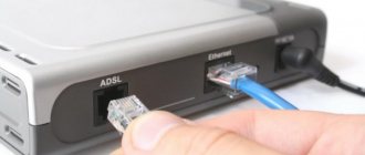
In a residential area, electrical wiring consists of an electrical input, a group electrical network that distributes energy from the electrical panel throughout the room, and, in fact, the electrical panel itself. For each group of consumers, electrical wiring is carried out using a cable with a certain cross-section and circuit breakers with previously calculated ratings.
Input and distribution devices
As mentioned earlier, the power cable coming from the substation goes to the IU (input device) or ASU (input distribution device). For an apartment building, their main difference from each other will be the availability of equipment for the distribution of energy throughout the building.
So, ASU is a set of protective devices (fuses, circuit breakers, and so on), devices and instruments for electricity metering (electricity meters, ammeters, and so on), electrical equipment (bus bars, switches, current transformers and other devices), as well as building structures, installed at the entrance to a building or residential premises, which include protective devices and metering devices (electricity meters) of outgoing electrical wiring lines.
You also need to remember that re-grounding lines are connected to both the VU and the ASU, which means that the splitting of the incoming PEN conductor can only be carried out here.
When using the TN-CS system, the combined PEN conductor coming from the substation must be split. The TN-CS system will only take place after splitting on the side of the transformer substation. In modern floor panels, three-phase circuit breakers and electric meters are usually installed. RCD and automatic devices.
After the ASU or VU, electricity is supplied to the floor electrical panels of the apartment building. When using the TN-CS system, five wires go to consumers (L1, L2, L3, N, PE).
And who would be interested in a little about the ASU:
Specifications
Each input switchgear has its own characteristics (with automatic transfer switch, without it, with automatic switches, etc.). Before starting installation, you need to study all the data specified in the device passports. Let's look at the characteristics of the most popular models:
VP – model with switches. VP VRU-8500:
| Rated current, A | 630 |
| Voltage, V | 0,4 |
| Wear resistance | Unlimited |
| Stability, kA | 10 |
| Panel dimensions, mm | 1800 (2000)*800 |
Depending on needs, overall dimensions may vary. ASU of this type is recommended for installation in in-house switchboards. Not suitable for outdoor use.
| Current, A | 250 |
| Voltage, V | 380 |
| Embedded elements | Transformer, capacitor, automatic switches. The 400 A model comes with a meter |
| frequency Hz | 50 |
| Usage | In three, four and five wire networks |
A VROOM type device has similar characteristics.
| Network requirement, A/V | 220/380 |
| frequency Hz | 50 |
| Additional requirements | The network must have a solidly grounded neutral |
| Generally accepted standards of ASU (GOST, TU) | TU 3434-007-05774835-2002. |
The description of this switchgear is somewhat different from those discussed above. It is mainly used for private or industrial buildings and is suitable for outdoor installation. Marking:
- VRU (VU) – Input switchgear;
- 3 – panel third in development;
- C – certificate of the plant, in this case, the Starookolsky plant;
- M - a device of a modernized series (with a counter, automatic machines and lighting control).
Video: ASU of an apartment building
Requirements and installation of ASU
To assemble any input distribution board or connect a finished device, you will need special circuits. Depending on the type of installation, you will need to obtain permission from your electricity supplier.
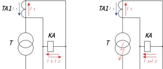
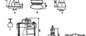
Photo - example of an input circuit
The photo shows approximate input diagrams of this type:
- Switches and fuses for single input (a);
- Single input and circuit breaker (b);
- Switches and fuses (c);
- Double input, similar to scheme B (d);
- double with AVR (d).
The price of an input switchgear depends on its parameters and size. In addition to checking compliance with the quality certificate, it is also necessary to analyze the requirements that each ASU must meet:
- In order for the device to operate reliably and without failures, it is very important to check that circuit breakers and other protective devices can be installed on all input and output lines;
- When connecting an ASU, each node is connected according to the color coding of the wires and their purpose. It is also recommended to mark the cables if repairs to the input switchgear are required;
- Before purchasing, be sure to calculate the required current and network voltage.
You can buy ASU in any city in Russia and the CIS countries: Moscow, Minsk and others. You can also purchase an old shield on radio markets or Internet portals. The cost varies from several hundred to tens of thousands of rubles.