When connecting private homes to an external power supply system, homeowners are faced with various problems and errors:
- discrepancy between the technical characteristics of the input equipment and the actual loads on the electrical network;
- insufficient level of electrical safety of the home electrical installation, the reason for which is the lack of necessary protection devices against electric shock;
- errors during connection of protective devices and violation of the sequence of their connection.
All this is caused by the lack of objective information about how to properly supply electricity to the house and what equipment should be equipped with the incoming electrical panel.
More precisely, many answers can be found to existing questions, but it is not so easy to find reliable information in them.
Rules for the installation of electrical installations, building codes, requirements of local power grid companies - if you delve into all this at the same time, you can quickly reach a dead end. Therefore, we would like to introduce you to the real experience of FORUMHOUSE users and the recommendations of specialists from the Legrand Group, our partners in the “HOUSE IN A YEAR” project with FORUMHOUSE.
Connecting power-receiving equipment in a private home is an issue that should be addressed by professionals. However, after reading the article, you can take note of a few recommendations for yourself.
Today you will learn:
- what are the requirements for the design of electrical panels;
- what devices electrical panels should be equipped with, and what functions the installed equipment performs;
- how to ensure selectivity of the home electrical installation;
- how to choose a protective device based on its performance characteristics;
- in what sequence to connect protective devices (RCDs, automatic circuit breakers, circuit breakers (CB)).
Organization of the entry point
During the connection process, a cable line (underground or overhead) is drawn from the street electricity metering panel (MU), located on the power transmission line tap-off support, to the distribution panel (DP), mounted indoors.
The metering panel (MCB) often contains only an input machine and an electricity meter. Circuit breakers, residual current devices and other elements, which will be discussed below, are installed in the distribution panel (DP), which is installed directly in the house.
In some cases, equipment for the control room and control panel can be installed in the same building.
The operating parameters of the equipment installed in the metering panel, its list and quantity - all this must be specified in the power supply project (or at least must be calculated by specialized specialists). But there are requirements that apply directly to the design of the electrical panel.
Sergey Savelyev Head of Technical Department of Legrand Group in Russia
The design of the electrical panel must ensure convenient supply of the power cable; it must contain neutral buses and grounding buses. At the same time, the electrical panel must have internal space sufficient to accommodate numerous outgoing cables, and its reserve necessary for possible expansion and modernization of the electrical installation.
We add that the body of the shield must be resistant to fire or made of self-extinguishing material. At the same time, he is obliged to reliably protect the built-in equipment from possible damage. A lock built into the door or dashboard handle will help prevent intentional damage, and protection from dust and moisture is guaranteed by the IP protection degree specified in the specification. If the shield is intended to be installed outdoors or indoors, where increased protection from moisture, dust and mechanical damage is required, then it is better to give preference to shields of class IP65 – IK09.
In order to avoid disagreements during the connection process with specialists from energy supply companies (whose requirements often contradict each other), a power supply project should be developed and agreed upon simultaneously with the architectural design.
If the connection point is organized in accordance with the requirements of the agreed electrical project, the owner of the site, as a rule, does not have problems during the connection process and further checks by regulatory organizations. Consequently, the work associated with installing and completing the electrical panel will not be in vain.
Let's talk about what the configuration of a home switchboard should be.
Photo tips for assembling the shield
1+
Read here! Electrical panel: general information and requirements for installation of main elements (125 photos)
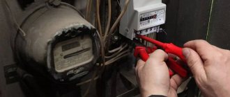
Input switch and meter
The starting point of a home electrical installation is considered to be the input switch to which the electric meter is connected, and other devices located after the meter.
Sergey Savelyev
The rating of the input AV is determined by the energy supply organization based on the allocated power. For example, with a three-phase input and 15 kW of allocated power, the rating is 25A. With a 1-phase input and 7.5 kW, the rating is 40 A. Moreover, if the power is more than 11 kW, the power supply must be three-phase. If there are three-phase consumers in the project, three-phase connection is allowed with an allocated power of less than 11 kW.
Transfer input device
If the electrical installation includes a source of autonomous power supply (for example, a diesel generator), then the system must have a reserve input device, which is installed after the electricity meter. We are talking about a switch that allows you to manually connect consumers to a generator or to an external power supply system. This device does not allow simultaneous use of two different power sources (transformer substation and diesel generator). This is its key advantage.
SPD
To protect the electrical installation from high-voltage pulses, from the consequences of a direct lightning strike and, as a result, from possible fires, it is necessary to integrate a surge protection device (SPD) into the system.
In the general diagram, SPDs are located immediately after the QF1 input device. In addition, the SPD should be connected to the circuit through a separate protection device QF2 (circuit breaker or fuse). The number of poles of the input device and SPD should be selected based on the number of phases and the operating mode of the neutral. (see diagram). When entering air into a building, installation of an SPD is mandatory!
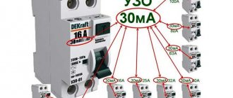
Fire protection RCD
Fire safety residual current devices are designed to protect against fire. Devices that operate at a rated differential current of 100 to 300 mA are used as fire protection RCDs. This is a fairly high setting and does not protect a person from electric shock. For this reason, certain consumer groups are equipped with additional (more sensitive) RCDs.
Recently, selective fire protection RCDs have become widespread.
Sergey Savelyev
Type “S” (selective RCD with response delay) - designed to ensure that in case of ground faults in lines (for example, in socket lines), only downstream RCDs of a specific line are triggered, and the fire RCD at the input continues to operate, powering healthy sections of the electrical wiring.
Cross module
In modern power supply systems, several groups of electrical consumers are often used (socket group, lighting, etc.). And in order to distribute the electricity supplied to the panel from the input cable between different groups, it is recommended to install a modular distribution block (cross-module) on the DIN rail. The cross-module allows you to insert one conductor into the panel, designed for a large load, and receive at the output several lines of a smaller cross-section (which depends on the load on a particular group of consumers).
In addition, installing a cross-module ensures reliable electrical connections and simplifies the process of connecting additional devices to an existing electrical panel.
Trimming cables inside an electrical panel
Using a special knife with a heel, the top insulation is removed from the cables without damaging the core covering. As a matter of priority, immediately after cutting, each cable should be re-labeled to avoid confusion. It is better to leave a spare length of wire that is approximately twice the distance to the fastening in the box from the entrance to it.
Instructions for separating cables:
- The order is observed: from the top - left to right, from the bottom left corner - to the right.
- The insulation is removed from the edge of the input cable.
- The wires are wrapped (5-10 cm to the end) with masking tape, and markings are applied.
- Operations are performed for each cable.
RCDs and circuit breakers (AB) for individual groups
Each consumer line leaving the cross-module is protected by separate circuit breakers and RCDs. When it comes to installing them in a distribution panel, two questions immediately arise:
- How to choose the right protective devices based on rating and differential cutoff current?
- How and in what sequence are RCDs and machines connected to each other?
We will try to give detailed answers to them. First, let's find out what functions the presented devices perform:
- An RCD protects a person from electric shock, but it cannot protect itself and the electrical installation from overcurrents and short circuit currents. Therefore, the power supply system must be equipped with both RCD and AV at the same time.
- Automatic switches do not react in any way to leakage currents, but protect the circuit from overloads and short circuits.
The protective action of an RCD is based on the principle of limiting (due to quick shutdown) the duration of current flow through the human body when it unintentionally touches live elements. Under normal conditions, the current flowing through the neutral wire is exactly equal to the current in the phase wire. If a difference occurs between them due to leakage to the ground through damaged insulation or through the human body, the device reacts to this by immediately turning off the network.
To understand what rating protection devices should have, let’s turn to the opinion of a specialist.
Sergey Savelyev
Socket lines (cable cross-section 2.5 mm²) are protected by 16A AB, lighting lines (cable cross-section 1.5 mm²) by 6 or 10 A AB. Consumers with a power of more than 3.5 kW are connected to the panel with a separate cable through a separate AB. In this case, the cable cross-section and AB rating must be calculated.
The AB housing is always marked with a letter designation of the device’s operating current category (for example, B16, C16). The number after the letter indicates the device rating in amperes. In household systems, AVs of the following categories are used: “B” and “C”. Devices of category “B” operate almost instantly when the current in the circuit increases to 3–5 nominal values. Category “C” devices are designed for instantaneous shutdown at 5–10 ratings. Consequently, category “B” circuit breakers are the most sensitive to short-circuit currents and are especially recommended for wooden house construction.
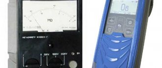
Now, as for the RCD: these devices are selected according to three parameters at once:
- According to rated current. The designation of the rated current is written in amperes and applied to the device body. In this case, the letters indicating the disconnection category (which are used to mark circuit breakers or differential circuit breakers) are not written on the RCD body.
- By rated differential current - the main parameter of the RCD, indicated in milliamps (10 mA, 30 mA, etc.).
- According to the category of leakage currents: devices of the group - “AC” - are triggered only by alternating leakage current. More sensitive devices (group “A”) respond to both alternating and pulsating leakage currents. In simple home systems, it is allowed to use devices from the “AC” group.
Sergey Savelyev
A 30 mA RCD is placed “at the head” of a group of circuit breakers (for example, 3-4 circuit breakers are connected to one RCD). The rated current of the RCD must be no less than that of the higher-level circuit breaker (as a rule, the higher-level circuit breaker is the input circuit breaker).
So, several AVs can be connected to each RCD, protecting separate groups of consumers.
If the rating of the RCD is greater than or equal to the rating of the higher-level circuit breaker, then several circuit breakers can be connected to such a RCD (even if the total rating of the circuit breakers is greater than the rating of the RCD). If the rating of the RCD is less than the higher-level CB, then several machines can be connected to the RCD, only under one condition: if their total rating does not exceed the rated current of the RCD.
Simply put, the RCD itself is under reliable protection if an AV whose rating is less than or equal to the rating of the RCD is connected to the circuit before or after the device.
And also about the nominal value of the RCD.
R0c0t FORUMHOUSE user
It is recommended to protect rooms with high levels of humidity (bathrooms, showers) with an RCD with a differential breaking current of 10 mA, if they have a separate line. In other cases, for example, if one line is allocated to several rooms (kitchen, bathroom, etc.), you should use an RCD with a differential operating current of no more than 30 mA (SP 31-110-2003).
How to calculate the number of places in an electrical panel?
Unified standard dimensions are provided for electrical equipment used to install the switchboard. Even from different manufacturers, switches and other components will have similar dimensions.
The main elements are mounted on a DIN rail, the width of this profile is 3.5 cm. For one circuit breaker, a “seat” is provided, 1.75 cm wide. Each box that manufacturers offer has a certain number of cells for modules.
To calculate how many spaces are needed for a distribution panel of a certain configuration, you need to know the exact number of elements needed, their type and size, and also provide approximately 20% for a reserve in case of changes during the assembly process or future purchases of electrical equipment. The dimensions of the devices are selected from the table below.
| Name | Width/number of seats |
| Single-pole automatic switch | 1.75 cm/1 place |
| Automatic switch, two-pole, single-phase | 3.5cm/2 places |
| Three-pole automatic switch | 5.25 cm/3 places |
| RCD single-phase | 3.5cm/2 places |
| Three-phase RCD | 7 cm/4 places |
| Single-phase differential automatic machine | 7 cm/2 modules for 4 places |
| DIN rail terminal block | 1.75 cm/1 place |
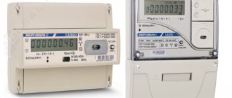
| Modular electricity meter | 10.5-14 cm/6-8 seats |
| Modular socket on DIN rail | 5.25 cm/3 places |
| Voltage relay | 5.25 cm/3 places |
The simplest distribution board will require the smallest number of elements - 20 pieces. For rooms with wiring consumption above 400 m, this figure increases significantly. Due to the fact that most equipment cases provide 24, 36 or a multiple of 12 seats, a simple case with 24 seats should be enough. It is better to purchase the 36 version, as there is more room for changes in the future.
Sequence of connecting RCDs and circuit breakers
The first connection rule: if a phase is taken from one RCD, then zero from all consumers connected to this phase must return to the original RCD. That is, the neutral and phase wires should not be mixed with other neutrals and phases after the RCD.
In the diagram we see two circuit breakers going to the lighting groups (protection of lighting lines using an RCD is not mandatory). The fire protection RCD is not indicated in this diagram. The socket groups are protected by a protective shutdown with a rating of 40 A and 30 mA.
Connection is simple:
- the lighting groups are not connected to the RCD, so the neutral and phase wires are branched off to them after the input circuit breaker;
- the phase for the socket groups is taken from one RCD;
- The zero of the socket group is connected to a separate zero busbar, which is also connected to the RCD.
When completing electrical panels, you should avoid situations in which an unlimited number of lines are connected to one RCD. To ensure this condition, the standard panel is equipped with several residual current devices. In this case, RCDs are grouped by type of connected premises and by type of load. For example, the socket group of the bathroom is connected to an RCD with a nominal value of 10 mA, and the socket groups of the kitchen and living quarters are connected to an RCD with a nominal value of 30 mA.
Installation of the electrical panel housing
Working with mounted devices is much easier than the hidden type. For the second option, you will need to make sure that the wall in which the shield will be installed is not load-bearing, and you can make a niche of the appropriate size. Without damaging the wall, a “false” surface is created, protruding by the thickness of the box or at least 10 cm.
To place the electrical panel, the following rules must be followed:
- It is best to place boxes in rooms with good lighting, air circulation, preferably close to the exit.
- The ambient humidity level should not exceed 60%.
- There must be at least 15 cm to the nearest slope, door or other protrusion; access during adjustment or repair must be free; placing an electrical panel in dressing rooms or closets is prohibited.
- There must be at least 1-1.5 m to the nearest gas pipeline or flammable substance;
- Installation is carried out no lower than 1.4 m and no higher than 1.8 m from the floor.
Step-by-step instructions for installing the electrical panel housing:
- A place for mounting the housing is outlined; using a level, 1 horizontal and vertical line of the edge of the device is drawn.
- The body attached to the marking site is outlined with a marker along the edge.
- Using a grinder, cuts are made to the middle of the disc along the drawn perimeter.
- A hole is made with a hammer drill or chisel to the thickness of the box.
- The fit of the box is tested and the bottom and walls of the niche are adjusted.
- A standard mount is placed on the body, and the entry points of the dowels are marked.
- Holes for fasteners are drilled using a hammer drill.
- The din frame is dismantled and equipped with the necessary modules.
- They are filled with polyurethane foam before final finishing of the cavity.
If the delivery set does not include fasteners for a flat wall, the box is nailed to the wall with dowels and mounted on alabaster or other mortar.
Differential machines
In practice, instead of residual current devices, differential circuit breakers are often used.
These are devices that combine RCD and AV in one housing. It makes sense to use automatic devices if this device will protect a separate line or an individual consumer. If you protect several lines with a difautomatic device, then each will need to additionally install its own AB (unless, of course, the selectivity of the system is important to you, and you do not want to violate it).
Electrical panel operation
The device requires regular maintenance:
- After a month after launch, the plastron is raised and the terminals are tightened.
- For homes with children, care should be taken to ensure that the electrical panel can be locked; the location of the key storage should be known to all adult family members.
- All residents of the apartment are told what to do when the protective devices are triggered.
- When electricity consumers are disconnected, the performance of all differential circuit breakers and RCDs is checked monthly.