Sections of the site
DirectAdvert NEWS
friends of site
Action Teaser NEWS
Statistics
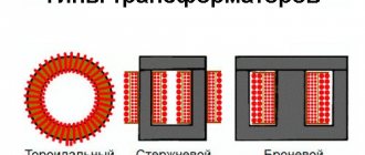
The magnetic core of the low-frequency transformer consists of steel plates. Using laminations instead of a solid core reduces eddy currents, which increases efficiency and reduces heat.
Magnetic cores of type 1, 2 or 3 are produced by stamping. Magnetic cores of types 4, 5 or 6 are produced by winding a steel tape onto a template, and magnetic cores of types 4 and 5 are then cut in half.
1, 4 – armored, 2, 5 – rod, 6, 7 – ring.
To determine the cross-section of the magnetic circuit, you need to multiply the dimensions “A” and “B”. For calculations in this article, the section size in centimeters is used.
Transformers with twisted rod position 1 and armored magnetic cores position 2.
Transformers with stamped armored magnetic cores, position 1, and core magnetic cores, position 2.
Transformers with twisted ring magnetic cores.
The overall power of a transformer can be approximately determined by the cross-section of the magnetic core. True, the error can be up to 50%, and this is due to a number of factors. The overall power directly depends on the design features of the magnetic core, the quality and thickness of the steel used, the size of the window, the amount of induction, the cross-section of the winding wire and even the quality of the insulation between the individual plates.
The cheaper the transformer, the lower its relative overall power. Of course, it is possible through experiments and calculations to determine the maximum power of a transformer with high accuracy, but there is not much point in this, since during the manufacture of the transformer, all this is already taken into account and reflected in the number of turns of the primary winding. So, when determining the power, you can be guided by the cross-sectional area of the set of plates passing through the frame or frames, if there are two of them.
Where:
P
– power in Watts,
B
– induction in Tesla,
S
– cross section in cm²,
1.69
– constant coefficient.
First, we determine the cross-section, for which we multiply the dimensions A and B.
Then we substitute the cross-sectional size into the formula and get the power. I chose 1.5Tc induction, since I have an armored twisted magnetic circuit.
If you need to determine the required cross-sectional area of the manipulator based on the known power, you can use the following formula:
It is necessary to calculate the cross-section of an armored stamped magnetic circuit for the manufacture of a 50-watt transformer.
The magnitude of induction can be found in the table. You should not use maximum induction values, as they can vary greatly for magnetic cores of different quality.
Maximum indicative values of induction.
HOW TO CALCULATE A STEP-DOWN TRANSFORMER.
In a household, it may be necessary to equip lighting in damp areas: basement or cellar, etc. These rooms have an increased risk of electric shock.
In these cases, you should use electrical equipment designed for a reduced supply voltage, no more than 42 volts. You can use a battery-powered electric flashlight or use a step-down transformer from 220 volts to 36 volts.
As an example, let's calculate and manufacture a single-phase 220/36 volt power transformer. To illuminate such rooms, a 36-volt electric light bulb with a power of 25-60 watts is suitable. Such light bulbs with a base for a standard socket are sold in electrical goods stores.
If you find a light bulb of a different power, for example 40 watts, there is nothing to worry about - that will do. It’s just that our transformer will be made with a power reserve.
Power in the secondary circuit: P2 = U2 • I2 = 60 watts
Where:
P2
is the power at the output of the transformer, we set 60 watts;
U2
is the voltage at the transformer output, we set it to 36 volts;
I2
is the current in the secondary circuit, in the load.
Transformer efficiency up to 100 watts
usually equal to no more than
η = 0.8
. Efficiency determines how much of the power consumed from the network goes to the load. The remainder goes to heating the wires and core. This power is irretrievably lost.
Let's determine the power consumed by the transformer from the network, taking into account losses:
Power is transferred from the primary winding to the secondary winding through the magnetic flux in the magnetic core. Therefore, the cross-sectional area of the magnetic circuit S depends on the value of P1, the power consumed from the 220 volt network.
The magnetic core is a W-shaped or O-shaped core made from sheets of transformer steel. The core will contain a frame with primary and secondary windings.
The cross-sectional area of the magnetic circuit is calculated by the formula:
Where:
S
is the area in square centimeters,
P1
is the power of the primary network in watts.
The value of
S
is used to determine the number of turns w per volt using the formula:
In our case, the cross-sectional area of the core is S = 10.4 cm2.
Let's calculate the number of turns in the primary and secondary windings.
Number of turns in the primary winding at 220 volts:
Number of turns in the secondary winding at 36 volts:
In load mode, there may be a noticeable loss of part of the voltage across the active resistance of the secondary winding wire. Therefore, for them it is recommended to take the number of turns 5-10% more than calculated. Let's take W2 = 180 turns.
The magnitude of the current in the primary winding of the transformer:
Current in the secondary winding of the transformer:
The diameters of the wires of the primary and secondary windings are determined by the values of the currents in them based on the permissible current density, the number of amperes per 1 square millimeter of conductor area. For transformers, the current density for copper wire is assumed to be 2 A/mm².
Read also: Brinell hardness tester
At this current density, the diameter of the wire without insulation in millimeters is determined by the formula:
For the primary winding, the wire diameter will be:
Wire diameter for secondary winding:
IF THERE IS NO WIRE OF THE REQUIRED DIAMETER, then you can take several thinner wires connected in parallel. Their total cross-sectional area must be no less than that corresponding to the calculated one wire.
The cross-sectional area of the wire is determined by the formula:
Where:
d is the diameter of the wire.
For example:
we could not find a wire for the secondary winding with a diameter of 1.1 mm.
The cross-sectional area of a wire with a diameter of 1.1 mm is equal to:
Let's round up to 1.0 mm².
From the table we select the diameters of two wires, the sum of the cross-sectional areas of which is equal to 1.0 mm².
For example, these are two wires with a diameter of 0.8 mm. and an area of 0.5 mm².
Or two wires:
- the first with a diameter of 1.0 mm. and a cross-sectional area of 0.79 mm², - the second with a diameter of 0.5 mm. and a cross-sectional area of 0.196 mm². which adds up to: 0.79 + 0.196 = 0.986 mm².
The coil is wound with two wires simultaneously; an equal number of turns of both wires is strictly maintained. The beginnings of these wires are connected to each other. The ends of these wires are also connected. It turns out like one wire with the total cross-section of two wires.
A power transformer is the simplest example of electrical energy conversion. Even with the constant improvement of radio-electronic devices and power supplies based on them, power supplies based on alternating voltage transformers do not lose their relevance.
Transformers for the power supply are large in size and weight, operate within a limited range of permissible input voltage, but are very easy to implement and are highly reliable and maintainable.
Types of magnetic cores
The basis of an AC transformer is a magnetic core, which must have certain magnetic properties. Transformers use steel of a special composition and with specific processing (transformer iron). During operation of the transformer, eddy currents are formed in the magnetic core, which heat the core and lead to a decrease in the efficiency of the transformer. To reduce eddy currents, the core is made not monolithic, but assembled from thin steel plates or strips coated with a non-conducting oxide layer.
Based on the type of metal used, cores are divided into:
The first type of cores is assembled in the form of a package of individual plates of the appropriate shape, and the second is wound from tape. In the future, the tape core can be cut into separate segments for ease of wire winding.
Cores are classified according to the type of magnetic circuit:
Each of the listed types may differ in the shape of the plates or segments:
The shape and type of the core in theory do not affect the calculation method, but in practice this should be taken into account when determining the efficiency and number of winding turns.
The ring (toroidal) core has the best properties. A transformer made on such a magnetic core will have maximum efficiency and minimum no-load current. This justifies the greatest labor intensity of winding, since at home this work is done exclusively by hand, without the use of a winding machine.
Repair of transformers and low-voltage devices - Magnetic cores
Page 16 of 38
MAGNETIC CIRCUIT OF POWER TRANSFORMERS The magnetic circuit * of a power transformer is a set of plates of electrical steel or other ferromagnetic material, assembled into a certain geometric shape, and serves to localize the main magnetic field of the transformer in it. It is the most important and structurally complex element of the transformer, participating in the energy conversion process and, together with the windings, constituting its active part. The magnetic core has a magnetic resistance depending on the length of the circuit, its cross-section and the properties of the material from which it is assembled1 - the magnetic permeability of steel. In order to reduce the magnetizing current for a given magnetic flux and, therefore, a given flux density per unit cross section (magnetic induction), it is necessary to significantly reduce the magnetic resistance of the active part of the magnetic circuit, i.e., make it from a material with high permeability. Such materials are hot-rolled and cold-rolled electrical (transformer) steels. In the transformer industry, the following grades of electrical steel were previously used: hot-rolled E22, E41, E42, E43, E43A and cold-rolled textured E310, E320, E330, E330-A, E330-AP. Currently, 38 grades of steel are used (GOST 21427.0 - 75). Designations of steel grades consist of four digits: the first digit indicates the class by structural condition and type of rolled product; the second is the silicon content, the third is the group according to the main standardized characteristic, the fourth is the serial number of the steel type. Electrical steels are divided: according to the structural state and type of rolled product into three classes (the first is hot-rolled isotropic **, the second is cold-rolled isotropic, the third is cold-rolled anisotropic ***); according to silicon content into six groups; according to the main standardized characteristic into five groups, determined by specific losses at the corresponding magnetic induction and frequency.
*Magnetic core is a short form of the standard term “magnetic system”.
**Isotropic refers to materials with identical physical properties in all directions.
***Anisotropic materials are those whose properties are not the same in different directions. Transformers with a magnetic core core made of anisotropic textured electrical steel are approximately 20 - 30% lighter than transformers with a magnetic core core made of conventional and previously widely used hot-rolled steel:
Hot-rolled isotropic electrical steel is produced in the form of sheets (GOST 21427.3 - 75), distinguished by rolling accuracy and thickness - normal (N) and increased (P) accuracy. Steel sheets are supplied in a heat-treated state with an etched (T) or unetched (NT) smooth surface that is free of rust, flaking scale and other defects that prevent the application of insulation to it. 4 Cold-rolled anisotropic electrical steel is produced in accordance with GOST 21427.1 - 75 and the SEV standard ST 102 - 74 and is divided according to the type of coating: with electrically insulating heat-resistant (ET), which does not impair stampability - soft (M), without coating (BP). Cold-rolled isotropic electrical steel is produced in 11 grades with heat-resistant electrical insulating coating (ET), with non-heat-resistant (E) and without coating (BP). The magnetic properties of electrical steels are characterized by magnetization, and losses in them from eddy currents and hysteresis are determined by specific losses (losses per 1 kg of steel at a frequency of 50 Hz and sinusoidal voltage). In transformer manufacturing, sheet and coil electrical steel is used, mainly with a thickness of 0.35 and 0.5 mm. Magnetic cores of transformers are assembled from electrical steel plates insulated with a film of heat-resistant coating or varnish *. Magnetic cores are a rigid structure on which LV and HV windings, taps, switches and other parts of the active part of transformers are installed and secured. There are two types of magnetic cores: rod and armored. The most common is the rod magnetic circuit (Fig. 31), which consists of vertical rods 1 with a stepped cross-section that fit into a circle. There are 2 cylindrical windings located on the rods. The upper and lower parts of the magnetic circuit, which have closing rods and do not have windings, are called magnetic circuit yokes. The yoke, connecting all the cores of the magnetic circuit, form a closed magnetic circuit and. at the same time they impart a certain rigidity and mechanical strength to the structure, which is extremely necessary, since the magnetic circuit is often subject to large dynamic forces caused by short circuits in the network.
*The core plates of the magnetic core of transformers of old designs are insulated with thin paper glued to the plate. Such transformers are still found quite often in repair practice.
The armored magnetic circuit (Fig. 32) has horizontally located rectangular rods on which rectangular windings are placed. In our country there are a small number of transformers in use from foreign companies and domestic ones with armor-type magnetic cores.
Rice. 32. Armored magnetic circuit Fig. 31. Rod magnetic circuit: 1 - rod, 2 - winding, 3 - yoke
Most of them are found in transformers of older designs. Repair companies, if necessary, reconstruct such transformers, significantly increasing their power and improving their characteristics. Currently, armored magnetic cores are not used in general-purpose transformers due to the complexity of their manufacturing technology. They are used only in certain types of special transformers, such as furnace transformers. Based on the method of connecting the rods to the yokes, a distinction is made between butt and laminated magnetic core designs. With a butt design, the rods and yokes are assembled separately, the windings are placed on the rods, and then the upper yoke is placed on top. To avoid shorting the plates, insulating spacers made of electrical cardboard are placed between the mating parts of the magnetic circuit. After installing the upper yoke, the entire structure is pressed and tightened with vertical pins. The butt design greatly facilitates assembly and disassembly, since to install and dismantle the windings, it is enough to remove the upper yoke. However, the butt design of a magnetic core is not free from disadvantages that are significant in the manufacture, repair and operation of transformers with such magnetic cores. These include: a high no-load current (approximately 1.5 times) than that of magnetic cores of a laminated design, and increased hum of the transformer during its operation. The higher no-load current is a consequence of continuous non-magnetic gaps between the yokes and rods. The strength of this current depends on the accuracy of cutting, stamping steel and assembling the magnetic circuit, as well as the thickness of the insulating gasket placed in the joints. The thicker this lining and the worse the accuracy of steel processing, the higher the magnetic resistance and, accordingly, the magnetizing current. The main difficulty in repairing a butt magnetic core is the creation of smooth butt surfaces of the yokes and rods. When the joint is skewed or the gaskets on different rods are unequally compressed, the rods that are poorly tightened in the axial direction, under the influence of the force of magnetic attraction, begin to vibrate between the yokes, breaking the insulating gasket. In this case, the sheets of active steel of the rods and yokes are closed and closed current circuits may appear in the transformer, leading to a serious accident (“steel fire”). Currently, magnetic cores of general-purpose power transformers are manufactured laminated. The rods and yokes are assembled into a binder, that is, they are divided in thickness into layers (usually two or three sheets) made up of individual plates so that in each layer part of the rod plates extends into the yoke. In this case, the plates of one layer overlap the joints of the plates of the adjacent layer. The advantages of a laminated structure over a butted one are lower weight and greater mechanical strength, small gaps at the joints and no-load current of transformers. However, with a laminated design, the assembly of the transformer becomes more complicated: to attach the windings to the rods, you first have to lamine the upper yoke in separate layers, and then, after fitting, the windings must be laminated again. Similar operations are performed when repairing transformers with damaged windings. Lashing requires great care in performing operations and extremely reducing the gaps between the plates of the rod and the yoke, since increased gaps between them worsen the conditions for the passage of magnetic flux and increase the no-load current of the transformer. In the domestic transformer industry, in the designs of core magnetic circuits, an “oblique joint” is used (formed by plates, the sides of which are most often cut at an angle of 45°) in order to reduce the section of the magnetic circuit in which the direction of the magnetic flux of the magnetic induction lines does not coincide with the direction of rolling of steel sheets. For cold-rolled electrical steel, from which magnetic cores of power transformers are currently made, this is of significant importance, since its magnetic conductivity along the rolling is much higher than at an angle to it. In oblique joints, the zone of some mismatch in the direction of flow and sheet rolling is limited to a small volume of steel adjacent to the joint of the plates, so the increase in losses in this area is less. Rice. 33. Magnetic core of a transformer with a power of 1800 kVA with tie rods passed through the holes of the rods and yokes: 1 - magnetic core, 2 and 12 - upper and lower yokes, 3 and 13 - upper and lower yoke beams, 4 - horizontal tie rod, pressing yoke , 5 - vertical compression stud, 6 - insulating gasket, 7 - holes for lifting studs, 8 - horizontal tie rod, compression rod, 9 - insulating tube of the vertical compression stud, 10 - steel support plate, 11 - wooden strip
Lashing of magnetic cores with oblique cuts in plates is more difficult than with rectangular sheets, and therefore the arrangement of the yokes is also more complicated, so the labor intensity of assembling a magnetic core with oblique joints increases significantly. In some designs of three-phase magnetic cores, oblique joints are limited only to the outermost rods. The middle rod is made with conventional straight joints. When using an oblique joint in the magnetic circuit design, no-load losses are reduced. The steel plates of the cores and yokes of the magnetic circuit must be firmly pressed, for which purpose in the transformer industry until recently special holes were created in active steel (by stamping the plates). Horizontal pins were inserted into these holes of the assembled magnetic circuit and with their help the rods and yokes of the magnetic circuit were tightened. To avoid shorting of the plates, which can cause an increase in eddy currents and strong local heating up to. “fire in steel”, the studs were reliably isolated from the active steel. However, the designs of magnetic cores with holes in the active steel of the rods and yokes (Fig. 33) have significant disadvantages. The holes are stamped on special presses (this is one of the most labor-intensive operations in the manufacture of magnetic cores); a zone of mechanically deformed steel appears around each hole (annealing of the plates is necessary to remove the resulting hardening); holes reduce cross-sections and cause a local increase in no-load losses. Finally, even the most reliable insulation of the studs that press the rods and yoke of the magnetic circuit can break down over time with serious consequences for the transformer.
Rice. 34, Magnetic core yoke, pressed with half-bandages: 1 - steel tape, 2 - pin, 3 - fiberglass plate, 4 - pressing nut, 5 - insulation of the steel pin with a tube
Therefore, designs of “pinless” magnetic cores have recently been widely used. There are quite a few designs of pinless magnetic cores, differing in the way the rods and yokes are pressed. Thus, for transformers with a power of 250 - 630 kV-A, the rods are tightened with temporary clamps in a horizontal position immediately after assembly. When installing windings (usually wound on a paper-bakelite cylinder), the clamps are removed, and wooden strips and wedges are installed between the cylinder and the magnetic circuit, rigidly pressing the rod plates. For transformers of higher power, the rods are pressed with steel or fiberglass bands. To avoid the formation of a closed loop, steel bandages are made with an insulating buckle. Bandages made of glass tape are wound using a special device that allows you to evenly lay the tape with the necessary tension for pressing the rod. To press the yokes, they use pins placed beyond the outer rods, tightening the yoke beams (the beams are made mechanically very strong), or steel half-bandages covering the upper and lower yokes. In some designs, instead of half-bandages, steel studs are installed, which, however, require some enlargement of the magnetic circuit window. The magnetic circuit yoke, pressed with steel half-bandages, is shown in Fig. 34. The half-bandage is a steel tape 1 with a width of 40 - 60 mm and a thickness of 4 - 6 mm (usually two tapes with a thickness of 2 - 3 mm are taken). Steel pins 2 are welded to the ends of the tape and passed through plates 3 made of durable insulating material (fiberglass is most often used). When tightening the nuts 4, screwed onto the studs, the necessary force is created to press the yoke. To avoid shorting the steel plates of the yoke with a half-bandage, place a box of electrical cardboard 2-3 mm thick under it. However, half-bandages alone cannot create forces sufficient to press the yoke. To tighten the yokes, special tightening devices must be used at the ends of the magnetic circuit, placed behind the active steel. These can be steel studs, insulated with paper-bakelite tubes 5 from possible short circuit with the rod. During operation of the transformer, an electric field exists between its windings and grounded parts (for example, a tank). All metal parts of the transformer located in this field are charged, that is, they acquire a certain potential. Potential differences arise between charged parts and a grounded tank. Despite their small size, they may be sufficient to break through small insulating gaps separating metal parts. Breakdowns are undesirable because they lead to decomposition and deterioration of the oil and are always accompanied by a characteristic crackling sound, which raises doubts about the serviceability of the transformer insulation. Therefore, the magnetic circuit and its fastening parts must be grounded, i.e., they are all given the same potential - the potential of the tank (ground); the resulting electrical charges “flow” through the groundings from the metal parts of the transformer into the ground. The yoke beams, all metal fasteners and parts are grounded, with the exception of horizontal tie rods, the potential of which is always close to the potential of the magnetic core steel. Grounding is carried out using copper strips inserted between the steel plates of the magnetic circuit and secured at the other ends to the yoke beam. The upper and lower beams are connected with vertical tie rods, and with the grounded transformer tank - with a lifting pin. Various methods of grounding metal parts are possible; they depend on the design of the magnetic circuit, the fastening of the active part in the tank, and the connection between individual parts. In any case, following the instructions on grounding individual elements of the transformer structure is mandatory. . The magnetic core is the most critical part; the normal and long-term operation of the transformer largely depends on its correct assembly and grounding method.
- Back
- Forward
Initial data
The initial data on the basis of which the transformer is calculated are necessarily:
- Mains voltage;
- Voltage and number of secondary windings;
- Load consumption currents.
For a complete and accurate calculation of a step-down transformer, it is necessary to take into account the temperature regime, permissible deviations in the voltage of the primary winding and some other factors, however, practice shows that transformers manufactured according to simplified calculation data have fairly good parameters. Next we will tell you how to calculate a transformer without resorting to complex and cumbersome calculations.
Calculation procedure
The calculation of a power transformer begins with determining the overall power. To begin with, the total total power of all secondary windings is determined:
How to calculate the power of a transformer if the power of the windings is unknown? The formula known from the physics course will help you find out:
The overall power of the transformer is calculated from the total, taking into account the efficiency, which differs for devices of different power. The following indicative efficiency values have been established experimentally:
- Up to 50 W – 0.6 (60%);
- From 50 to 100 W – 0.7 (70%);
- From 100 to 150 W – 0.8 (80%).
A more powerful transformer will have an efficiency of 0.85.
Thus, the calculation of overall power looks like this:
Рг = efficiency∙Рс, where Рс – total power.
Based on the overall power of the transformer, the cross-sectional area of the magnetic circuit can be determined:
According to this formula, the required cross-sectional area is obtained in square centimeters. Based on the data obtained, a core with a similar or slightly larger cross-sectional value is selected. Using collapsible cores made of W and U shaped plates, you can change the thickness of the set within certain limits by adding or removing several plates.
How to determine the power of an unknown transformer? It is necessary to square the area of the core, expressed in square centimeters.
Note! The cross-section of the magnetic circuit should, if possible, have a shape close to a square.
After selecting the magnetic core, we calculate the winding data. Having a magnetic core and knowing its cross-sectional area, you can calculate the transformer windings (the number of turns in the windings). It is customary to take the number of turns per 1 V of voltage as the basis for the calculation, since this number is the same for all windings and depends on the characteristics of the magnetic circuit and the frequency of the supply voltage. The complete formula, which takes into account the network frequency and magnetic induction in the core, is very complex and is almost never used in calculations. Instead, a simplified version is used that takes into account only the material and design of the core:
Read also: Homemade CNC machine from printers with your own hands
N=k/S, where k is a coefficient from the following list:
- W and P shaped magnetic circuit plates – k = 60;
- Tape core – k = 50;
- Toroidal magnetic circuit – k = 40.
As you can see, when using a toroidal core, the number of turns will be minimal.
Knowing the number of turns per volt, it is easy to determine the winding data of the windings for any voltage:
For the primary winding it will be:
Note! Since for step-down transformers the cross-section of the wire and the number of turns of the network winding are larger than all others, the ohmic losses in the wires will also be higher, therefore for low-power transformers (up to 100 W) these losses must be taken into account by increasing the number of turns of the primary winding by 5%.
If a rod-type transformer is being calculated, then usually the windings are divided in half and wound evenly on both rods. Parts of identical windings are then connected in series.
An equally important step in calculating a transformer is determining the cross-section of the winding conductors. Here, the value of current in the wires that causes minimal heating is taken as a basis. The higher the cross-section of the wire, the lower the current density per unit cross-section and, accordingly, the less heating. But an excessive increase in the cross-section of the winding wires leads to an increase in the mass of the transformer, an increase in cost, and also the likelihood that the windings simply will not fit into the windows of the magnetic circuit.
It is generally accepted that the optimal current density in windings is 4-7 A per 1 mm2. A lower density value is used to calculate the cross-section of the wires of the primary winding or any other that is closer to the core of the magnetic circuit. These windings have the worst cooling conditions.
In order not to operate with current densities and complex formulas for converting cross-sectional area to diameter, you can calculate the diameter using their simplified version:
- d = 0.7∙√I – for conductors of the primary winding;
- d = 0.6∙√I – for conductors of secondary windings.
For the windings, an insulated winding wire is used with a cross-section closest to the design one, but not less than it.
Important! The formula gives the calculated value for a bare wire, excluding insulation.
To measure the diameter of an unknown wire, a micrometer is needed. You can approximately determine the diameter by winding ten turns on a pencil and measuring the length of the winding.
To determine whether the windings will fit in the windows of the magnetic circuit, calculate the fill factor of the window:
K=0.008∙(d12 ∙w1+ d22 ∙w2+ d32 ∙w3+…)/Swindow.
If the resulting value is greater than 0.3, then the windings will not fit, and rewinding a half-finished device will not lead to a good result. There are several ways out:
- Use a magnetic core with a large cross-section;
- Increase the current density in the windings (no more than 5%);
- Reduce the number of turns in all windings at the same time (also no more than 5%).
Reducing the number of turns will lead to increased no-load current and losses in the transformer, which will be expressed in an increase in its temperature. Therefore, the use of the last two methods can only be recommended as a last resort.
Magnetic core designs
Structural device of a 1-phase transformer
The main design elements of a transformer are the magnetic core and windings.
The main types of magnetic systems of 1-phase transformers are rod and armored (Fig. 2.2). In rod transformers, single-phase windings are located on two rods and connected in series or parallel. The rod is the part of the magnetic circuit on which the windings are located. The part of the magnetic circuit on which there are no windings is called a yoke. Armored transformers have an extensive magnetic system that partially covers the windings, armoring them. The magnetic flux in the rod is twice as large as in the yokes, which therefore can have half the cross-section.
Single-phase low-power armored transformers are common: radio, bell, etc. The domestic industry does not produce armor-type power transformers.
The main advantage of rod-type transformers is the cylindrical shape of the windings, which are simpler and more technologically advanced than the disk alternating windings of armored transformers.
The magnetic core of the power transformer is made of cold-rolled electrical steel grades 3413, 3414. To reduce losses from eddy currents, the magnetic core is assembled from insulated sheets, sheet thickness 0.35...0.5 mm. Based on the manufacturing technology, a distinction is made between butt and interlocking magnetic circuits (Fig. 2.3, a, b). In butt cores, the bars and yokes are assembled separately from sheets of steel and then connected using a system of vertical studs. In cores laminated into a binding, the layers alternate, the junction of one layer is covered by a continuous sheet of another. After assembling the core, the sheets of the upper yoke are removed, windings are placed on the rods and the sheets are laminated again. With a butt design, the attachment of windings is carried out more simply. In the butt magnetic circuit, an insulating gasket must be placed between the rod and the yoke to avoid shorting the plates. In the presence of an insulating gasket, the magnetic resistance increases significantly and the magnetizing current of the transformer increases. The fastenings in the butt magnetic circuit are more complex and massive; the yokes must be tightly fastened to the rods. The laminated core has a more rigid structure.
Currently, magnetic cores of a butt design are used quite rarely. For powerful power transformers, a laminated binding design is adopted.
The cross-section of the magnetic cores of powerful power transformers is stepped, approaching a circle in shape (Fig. 2.4, a). This shape ensures that the required cross-section of the rod is obtained with a minimum diameter. The more steps, the closer the cross section is to the circle, the larger the active cross section of the rod for a given diameter.
The yokes connecting the rods are usually of rectangular or stepped cross-section. In transformers of modern series, the cross-sectional shape of the yoke usually follows the cross-sectional shape of the rods. The cross-sectional shapes of the yoke are shown in Fig. 2.4, b. The yoke is usually performed 2 ... 5% more than
Rice. 2.4. Cross section of the rod (a) and yoke (b)
cross section of rods. This reduces the induction in the yoke steel and the power loss in it.
Making windings
The transformer windings are made on a frame made of insulating material. The frame can be solid or collapsible. Despite its apparent complexity, a collapsible frame is easier to make, and its dimensions can be easily calculated to fit any existing core. From the materials for the frame, you can take sheet getinax, textolite or fiberglass. In the cheeks of the frame you need to provide holes for the leads.
The winding terminals are made with flexible stranded wire, carefully insulating the soldering area. The winding itself is carried out, if possible, turn to turn. Such winding allows better use of free space, reduces wire consumption, and most importantly, at the intersections of wires, if the winding is poorly executed, there is a risk of damage to the insulation and interturn short circuits. This rule does not apply to thin wire with a diameter of less than 0.2 mm, since it is very difficult to carry out an ordinary winding on it at home.
Each winding must be insulated from one another, especially the primary winding. For insulation, you can use several layers of FUM tape. It is made of fluoroplastic, which has good electrical insulating properties.
Important! FUM tape has a small thickness, and fluoroplastic has fluidity, so you need to make several layers of insulation.
Transformer windings
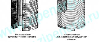
Transformers of sizes I-II have mainly cylindrical two- and multilayer windings (Figure 8). LV windings are wound with rectangular wire, and HV windings are wound with round wire. The cross-section of a turn of the LV winding is significantly larger than that of the HV winding, since the number of turns of the LV winding is smaller, and the current in it is greater (the ratio of currents in the LV and HV windings is related to the ratio of their voltages and, depending on the circuit and group of connections of the windings, is included in the determination of the coefficient transformation). A turn of the LV winding with a low rated voltage (230 V), shown in Figure 6, consists of two parallel wires. The wires are insulated with paper insulation, which is sufficient to provide insulation between turns. Adjacent layers are additionally insulated with cable paper. The number of layers depends on the power of the transformer. Starting from a power of 100 kVA, all layers of each winding are divided into two parts by a cooling channel formed by wooden or electrocardboard slats.
Rice. 8 - Windings of transformers of sizes I-II (a - LV winding - two-layer with two parallel wires; b - HV winding - multilayer)
Transformer factories produce LV and HV windings separately. Each winding is wound on a paper-bakelite cylinder with a thickness of 1.5-2.5 mm, and then the LV winding is pressed into the HV winding with an interference fit (together with the slats forming a channel between the windings). Previously, assembled and tested windings were impregnated with glypthal varnish and then baked in ovens at atmospheric pressure and a temperature of 80-90 ° C. The windings became rigid, monolithic, which was supposed to protect them from mechanical damage. However, special tests have proven that the mechanical strength of the windings increases slightly due to impregnation, but this creates some convenience during assembly. But impregnation does not increase the dynamic stability of the windings during short circuits in the transformer. More effective measures, which are now used by both transformer and electrical repair plants, are: the introduction of magnetosymmetric winding circuits; phase-by-phase winding, in which the HV winding is wound directly onto the LV winding, without removing it from the machine, etc. It should also be taken into account that transformer oil with the additives currently used dissolves glyphthalic varnish over time, which goes into sludge. A pilot batch of transformers with non-impregnated windings was manufactured and successfully passed a series of special tests. And now the windings of transformers of sizes I-II are not impregnated. Some transformers of the old series had windings of other types: screw (TSMAN), continuous (type TM-560/10). The internal insulation of a transformer consists of main winding insulation, longitudinal winding insulation, tap insulation and tap changer in relation to the tank and other grounded parts. The main winding insulation isolates the windings from each other and from grounded parts (Figure 9). This, in addition to the winding cylinders and oil channels between the magnetic core and the LV winding and between the LV and HV windings, is an interphase partition (between the HV winding of different phases) made of a sheet of electrical cardboard 2-3 mm thick, as well as yoke and equalizing insulation.
Rice. 9 - Main insulation of windings (a - insulation diagram b - placement of parts of the main insulation of phase A windings; windings in the transformer)
Yoke insulation insulates the windings from the yoke and is located at the top and bottom between the end part of the winding and the equalizing insulation. The latter aligns the plane of the yoke beams with the horizontal plane of the yoke. The designs of yoke and equalizing insulation for transformers of sizes I-II are very different. Figure 10 shows yoke insulation, which is a ring-shaped washer made of electrical cardboard 2-3 mm thick with pads attached on both sides. Equalization insulation is made in the form of a flooring made of wooden planks. Sometimes this flooring serves as both yoke and equalizing insulation, and electrical cardboard panels are installed between the winding and the yoke.
Rice. 10 - Yoke insulation
Longitudinal winding insulation includes turn insulation and insulation between winding layers. The insulation of the taps and the tap switch relative to the tank and other grounded parts of transformers of sizes I-II is only an oil gap, its value depends on the voltage and on the shape of the grounded and current-carrying parts: with a pointed shape the oil gap is larger, and with a flat one it is smaller. For 10 kV transformers, the HV winding is at least 25 mm away from the tank wall; outlet with solid insulation 2 mm thick per side - no less than 10 mm. Taps are wires connecting the ends of the windings to each other, to the inputs and to the tap switch. LV bends are made of aluminum busbars. At voltages up to 525 V they are not insulated. The cross-section of the taps is selected based on the current density of no more than 4.8 A/m m². HV taps are made of copper rods or flexible copper cable. Rods with a diameter of up to 5.2 mm are insulated with cable paper; for larger diameters, paper-bakelite tubes are placed on them. For insulated copper taps, the permissible current density is 2.5 A/m m².
Transformer assembly
The quality of the transformer largely depends on the correct assembly of the magnetic circuit. When assembling the W-shaped armor core, adjacent plates must be laid alternately in different directions. The plate pack should be stacked as tightly as possible. After assembly, it must be tightened tightly with screws. A loose transformer makes a lot of noise during operation. Particular attention should be paid to the tight fit of the W-shaped plates with the floor plates. The gap between them will lead to the core becoming open-circuited, and this implies the following:
- Increased no-load current;
- Decrease in efficiency;
- Increased magnetic scattering field.
When assembling a split strip core, you need to pay attention to the fit of the parts to each other, since during manufacturing they are adjusted by grinding. To reduce noise, the ends of the plate packages can be coated with a layer of varnish.
Read also: Adapter for connecting the filter to the mixer
Note! Parts of the tape magnetic circuit require careful handling, since delaminated tapes are almost impossible to install in their original place. The plates of the collapsible core cannot be bent or subjected to impacts, as this will disrupt the structure of the metal and it will lose its properties. As a last resort, plates bent at a large radius must be carefully bent by hand and, when assembled, placed in the middle of the plate pack. With further screeding they will align.
Calculating a network transformer is not difficult. It is more important to determine the requirements for it. The accuracy of further calculations will depend on the correctness of the task. For a power transformer, the calculation can also be conveniently performed using an online calculator. The step-up transformer is calculated using the same method.
Features of the assembly of plate magnetic cores
The procedure consists of a set of plates in a package and their fastening (pulling) together. The parts are connected in several ways:
- studs and bolts;
- crimping staples;
- metal holder.
An important assembly condition is the isolation of fasteners from the magnetic circuit. In some cases, the package is compressed. In this case, a change in magnetic permeability and electrical resistance occurs. The procedure is performed at a pressure of 2-5 MPa, the compression force is selected depending on the materials and design of the plates.
After compression, quality control must be carried out. With its help, it is possible to find out the resulting magnetic induction and permeability, as well as the no-load current of the plate magnetic circuit.
Compliance with a precise technological process allows us to obtain reliable and durable structures that can withstand heavy loads and are ready for use in almost any conditions.
Video
The simplest calculation of a power transformer allows you to find the cross-section of the core, the number of turns in the windings and the diameter of the wire. The alternating voltage in the network is 220 V, less often 127 V and very rarely 110 V. For transistor circuits, a constant voltage of 10 - 15 V is needed, in some cases, for example, for powerful output stages of low-frequency amplifiers - 25 ÷ 50 V. To power the anode and screen circuits of electronic lamps most often use a constant voltage of 150 - 300 V, to power the incandescent circuits of lamps an alternating voltage of 6.3 V. All voltages necessary for any device are obtained from one transformer, which is called a power transformer.
The power transformer is made on a collapsible steel core from thin W-shaped, less often U-shaped plates isolated from each other, as well as hollowed-out strip cores of the ShL and PL types (Fig. 1).
Its dimensions, or more precisely, the cross-sectional area of the middle part of the core, are selected taking into account the total power that the transformer must transmit from the network to all its consumers.
A simplified calculation establishes the following relationship: the cross-section of the core S in cm², squared, gives the total power of the transformer in W.
For example, a transformer with a core having sides of 3 cm and 2 cm (Sh-20 type plates, set thickness 30 mm), that is, with a core cross-sectional area of 6 cm², can consume 36 W of power from the network and “process” it. This simplified calculation gives quite acceptable results. And vice versa, if a power of 36 W is needed to power an electrical device, then taking the square root of 36, we find out that the cross-section of the core should be 6 cm².
For example, it should be assembled from Sh-20 plates with a set thickness of 30 mm, or from Sh-30 plates with a set thickness of 20 mm, or from Sh-24 plates with a set thickness of 25 mm, and so on.
The core cross-section must be matched to the power so that the core steel does not fall into the magnetic saturation region. And hence the conclusion: the cross-section can always be taken in excess, say, instead of 6 cm², take a core with a cross-section of 8 cm² or 10 cm². It won't get any worse. But it is no longer possible to take a core with a cross-section smaller than the calculated one, since the core will fall into the saturation region, and the inductance of its windings will decrease, their inductive resistance will drop, the currents will increase, the transformer will overheat and fail.
A power transformer has several windings. Firstly, network, connected to a network with a voltage of 220 V, it is also primary.
In addition to the network windings, a network transformer can have several secondary windings, each with its own voltage. A transformer for powering tube circuits usually has two windings - a 6.3 V filament winding and a step-up winding for the anode rectifier. In a transformer for powering transistor circuits, there is most often one winding that powers one rectifier. If a reduced voltage needs to be supplied to any stage or circuit node, it is obtained from the same rectifier using a quenching resistor or voltage divider.
The number of turns in the windings is determined by an important characteristic of the transformer, which is called the “number of turns per volt,” and depends on the cross-section of the core, its material, and the grade of steel. For common types of steel, you can find the "number of turns per volt" by dividing 50-70 by the cross-section of the core in cm:
So, if you take a core with a cross-section of 6 cm², then the “number of turns per volt” will be approximately 10.
The number of turns of the primary winding of the transformer is determined by the formula:
This means that the primary winding at a voltage of 220 V will have 2200 turns.
The number of turns of the secondary winding is determined by the formula:
If a 20 V secondary winding is needed, it will have 240 turns.
Now we select the winding wire. For transformers, copper wire with thin enamel insulation (PEL or PEV) is used. The wire diameter is calculated based on low energy losses in the transformer itself and good heat dissipation using the formula:
If you take a wire that is too thin, then, firstly, it will have high resistance and generate significant thermal power.
So, if we take the primary winding current to be 0.15 A, then the wire needs to be 0.29 mm.
The principle of operation of a transformer.
The operating principle of the transformer is based on the phenomenon of electromagnetic induction
.
If alternating voltage U1
, then an alternating current
Io
an alternating magnetic field
around the winding and in the magnetic circuit .
The magnetic field forms a magnetic flux Фo
, which, passing through the magnetic circuit, crosses the turns of the primary and secondary windings and induces (induces) alternating emf in them -
e1
and
e2
.
And if a voltmeter is connected to the terminals of the secondary winding, it will show the presence of output voltage U2
, which will be approximately equal to the induced emf
e2
.
When a load, for example an incandescent lamp, is connected to the secondary winding, a current I1
F1
in the magnetic circuit , changing with the same frequency as the current
I1
.
Under the influence of an alternating magnetic flux, a current I2
, which in turn creates a counteracting magnetic flux
F2
, tending to demagnetize the magnetic flux generating it.
As a result of the demagnetizing effect of the F2
In the magnetic circuit, a magnetic flux
Фo
equal to the difference between the fluxes
Ф1
and
Ф2
and being part of the flux
Ф1
, i.e.
Resulting magnetic flux Фo
ensures the transfer of magnetic energy from the primary winding to the secondary and induces an electromotive force
e2
, under the influence of which current
I2
.
It is due to the presence of magnetic flux Фо
I2
exists , which will be greater the greater
Фо
.
But at the same time, the greater the current I2
, the greater the counteracting flow
F2
and, therefore, the less
Fo
.
From the above it follows that at certain values of magnetic flux F1
and the resistance
of the secondary winding
and
load
e2
, current
I2
and flux
Ф2
are set , ensuring the balance of magnetic fluxes in the magnetic circuit, expressed by the formula given above.
Thus, the flux difference Ф1
and
Ф2
cannot be equal to zero, since in this case there would be no main flow
Фo
Ф2
and current
I2
could not exist .
Consequently, the magnetic flux Ф1
, created by the primary current
I1
, is always greater than the magnetic flux
Ф2
, created by the secondary current
I2
.
The magnitude of the magnetic flux depends on the current creating it and on the number of turns of the winding through which it passes.
The voltage of the secondary winding depends on the ratio of the number of turns in the windings
.
With the same number of turns, the voltage on the secondary winding will be approximately equal to the voltage supplied to the primary winding, and such a transformer is called an isolation
.
If the secondary winding contains more turns than the primary, then the voltage developed in it will be greater than the voltage supplied to the primary winding, and such a transformer is called a step-up
.
If the secondary winding contains fewer turns than the primary, then its voltage will be less than the voltage supplied to the primary winding, and such a transformer is called a step-down
.
Hence. By selecting the number of turns of the windings, at a given input voltage U1
obtain the desired output voltage
U2
. To do this, they use special methods for calculating the parameters of transformers, with the help of which the windings are calculated, the cross-section of the wires is selected, the number of turns is determined, as well as the thickness and type of the magnetic core.
The transformer can only operate in alternating current circuits . If its primary winding is connected to a direct current source, then a magnetic flux is formed in the magnetic circuit, constant in time, in magnitude and direction. In this case, an alternating voltage will not be induced in the primary and secondary windings, and therefore, electrical energy will not be transferred from the primary circuit to the secondary. However, if a pulsating current flows in the primary winding of the transformer, then an alternating voltage will be induced in the secondary winding, the frequency of which will be equal to the ripple frequency of the current in the primary winding.