Parallel oscillatory circuit
Ideal oscillatory circuit
In the diagram, an ideal oscillatory circuit looks like this:
Where
L - inductance, Henry
C - capacitance, Farad
Real oscillating circuit
In reality, our coil has a decent loss resistance, since it is wound from wire, and the capacitor also has some loss resistance. Capacitance losses are very small and are usually neglected. Therefore, we will leave only one coil loss resistance R. Then the diagram of a real oscillating circuit will take this form:
Where
R is the circuit loss resistance, Ohm
L - inductance, Henry
C - capacitance, Farad
Operating principle of a parallel oscillating circuit
Let's connect a real parallel oscillatory circuit to the frequency generator
What will happen if we apply a current to the circuit with a frequency of zero Hertz, that is, direct current? It will calmly run through the coil and will be limited only by the loss resistance R of the coil itself. No current will flow through the capacitor, because the capacitor does not allow direct current to pass through. I wrote about this in the article: capacitor in direct and alternating current circuits.
Let's add frequency then. So, as the frequency increases, our capacitor and coil will begin to provide reactance to the electric current.
The reactance of the coil is expressed by the formula
and the capacitor according to the formula
You can read more about this in this article.
If you gradually increase the frequency, you can understand from the formulas that at the very beginning, with a smooth increase in frequency, the capacitor will have greater resistance than the inductor. At some frequency, the reactances of the XL coil and the XC capacitor will be equal. If you further increase the frequency, then the coil will already have greater resistance than the capacitor.
Types and features
Oscillatory circuit circuits come in two types: series and parallel. They differ in the type of connection of capacitance and inductance elements. In the first case they are connected in series, and in the second - in parallel. Constant electrical energy is required for operation, otherwise it is attenuated, since part of it is spent on generating an electromagnetic field and heating the wire of the inductor winding. The circuit can also be open or closed. The open version is produced without a special protective cover.
When solving problems in physics, you can come across an interesting concept - an ideal oscillatory circuit. If such a term appears in the task, then this indicates that the energy remains in the system and does not go to the processes described above.
The device constantly generates electromagnetic oscillations, that is, it is a kind of perpetual motion machine, but this cannot exist at all. In practice, when calculating parameters, attenuation is taken into account - gradual decreases in the amplitude of the electromagnetic wave.
Serial connection
A series circuit is the simplest resonant-oscillatory system. It consists of two elements connected in series. When an alternating voltage is connected, a current of an alternating component will flow through them. Its value is determined by Ohm's law: i = U / Zlc. In this formula, Zlc is the sum of the reactances of the inductor (Xl) and capacitor (Xc).
The values are determined by the formulas Xl = wL and Xc = 1 / (wC). Parameter w is the angular frequency, which can be found from this relationship through the frequency of the alternating current and the number Pi: w = 2 * Pi * f. From the relationships we can conclude that the reactance for inductance increases with increasing f, and for capacitance it decreases. In the first case, the type of dependence is called directly proportional, and in the second - inversely proportional.
At a certain frequency value, the resistances of two elements are equal in magnitude to each other. Therefore, this phenomenon is called resonance of the oscillatory system. The frequency w under this condition is called the natural resonant frequency of the circuit. It is quite simple to calculate, since you need to equate two formulas to obtain the equation: wL = 1 / (wC). Next you need to express the value of f: f = [(1 / (L * C))^(½)] / 2Pi. The last relation is called Thomson's formula.
When the circuit is connected to the circuit of an alternating voltage generator (source) with active resistance R, the total impedance of the circuit (Z) is determined using the relation Z = [R2 + Zlc2]^(½). If resonance occurs, then Z = R, and the reactive component disappears.
The circuit has two more important characteristics: quality factor (Q) and characteristic impedance (p). The latter is the value of reactive type resistance at resonance. It is calculated using the formula p = (L * C)^(½) and shows the amount of energy of the coil and capacitor that has been stored. For capacitance, the value is determined by the relation Wc = (C * U2) / 2, and for inductance - Wl = (L * I2) / 2.
The ratio of the amount of energy that was stored by the capacitor and coil to the loss rate is called the quality factor of the oscillating circuit (Q). The parameter determines the amplitude and width of the frequency response of the resonance and shows the excess of the reserve energy over the losses for one oscillation. In this case, the reactive load R is taken into account The characteristic is determined by the formula Q = (1 / R) * [(L / C)^(½)].
In some cases, the quality factor can be described by another identity: Q = p / R. Modern devices are made on discrete coils, and their Q ranges from several units to hundreds. Systems built on the principle of piezoelectronic devices (quartz resonators) have a high Q index. Its value can reach 1 thousand or more. Circuit attenuation (d) is a characteristic that is the inverse of quality factor. It is determined by the following relationship: d = 1 / Q.
Parallel circuit
The parallel type circuit also consists of a capacitor and a coil. The difference is that these two elements are connected in parallel to each other. This type of device is used more often than a series circuit. To find the total inductive resistance, you cannot simply add the values of Xl and Xc. Only the conductivities of the two elements are added.
From the physics course it is known that conductivity is the reciprocal of resistance, that is, Xc = 1 / Gc and Xl = 1 / Gl. Therefore, the formulas for a parallel connection are as follows:
- Gl = 1/wL.
- Gc = wC.
- Q = R * [(C / L)^(½)].
For example, it is necessary to consider an electrical circuit consisting of an alternating current generator and a parallel circuit. At some point in time, their frequencies will coincide. In addition, the conductivities of the two elements are equal in magnitude to each other. As a result, the phenomenon of current resonance occurs.
The circuit will only have active resistance Req, which is called equivalent in radio engineering. It is calculated using the formula Req = Q * p. If the frequency does not correspond to the resonant one, then other processes occur in the device: at low frequencies, a decrease in inductive resistance is observed, and at high levels, a decrease in capacitive resistance is observed.
During operation of the circuit, energy is exchanged between the coil and the capacitor twice during the oscillation period. A current flows in the radio element, the strength exceeding the external one by Q times.
Resonance of a parallel oscillatory circuit
A very interesting property of a parallel oscillatory circuit is that when XL = XC our oscillatory circuit will go into resonance . At resonance, the oscillatory circuit will begin to provide greater resistance to alternating electric current. This resistance is also often called the resonant resistance of the circuit and is expressed by the formula:
Where
Rres is the circuit resistance at the resonant frequency
L is the actual inductance of the coil
C is the actual capacitance of the capacitor
R - coil loss resistance
Device detuning
Detuning is the tuning of a circuit to a frequency other than the resonant one. The latter occurs when the frequency characteristics of the radio component and the generator coincide. In some devices this must be avoided. To obtain resonance, you need to use one of three methods of changing characteristics:
- generator frequency;
- inductance;
- containers.
The last two methods can be done simultaneously to achieve better results. Disorders are classified into three types: absolute, generalized and relative. The first is the difference between the frequencies of the circuit and the resonance. The generalized one is calculated using the ratio of reactance to active resistance. Relative is expressed as the ratio of absolute detuning to resonant frequency.
In addition, frustration can be positive and negative. In the first case, it is necessary that the generator frequency be greater than the circuit frequency. For negative, another condition must be met: the frequency of the generator is less than that of the circuit.
In some cases it is necessary to remove the resonant frequency. This operation is performed by changing the necessary characteristics of the electrical circuit “circuit - generator”. Very often capacitors with variable capacitance are used in the circuit , allowing it to be tuned. The capacitor is adjusted by changing the distance between its plates. This principle is very convenient, since to change the inductance of the coil, a core is needed that will be unscrewed.
However, there are radioelements of this type. In them, the capacitance is a constant value, and the inductance changes with the help of the core. The design feature of the latter is an ordinary ferrite bolt, which is screwed into a plastic housing. The wire is wound around the latter.
How to find the resonance of a parallel oscillatory circuit in practice
Okay, let's get to the point. We take the soldering iron in our hands and solder the coil and capacitor in parallel. The coil is 22 µH, and the capacitor is 1000 pF.
So, the real diagram of this circuit will be like this:
In order to show everything clearly and clearly, let’s add a 1 KOhm resistor in series to the circuit and assemble the following circuit:
We will change the frequency on the generator, and we will remove the voltage from terminals X1 and X2 and watch it on an oscilloscope.
It is not difficult to guess that the resistance of the parallel oscillatory circuit will depend on the frequency of the generator, since in this oscillatory circuit we see two radio elements whose reactance directly depends on the frequency, so we will replace the oscillatory circuit with the equivalent resistance of the circuit Rcon.
A simplified diagram would look like this:
I wonder what this circuit looks like? Is it a voltage divider? Exactly! So, remember the rule of the voltage divider: at a lower resistance, a smaller voltage drops, at a higher resistance, a larger voltage drops. What conclusion can be drawn in relation to our oscillatory circuit? Yes, everything is simple: at the resonant frequency, the resistance Rcon will be maximum, as a result of which a greater voltage will “drop” at this resistance.
We have a resistor calculator by color. The coolest collection.
Let's begin our experience. We increase the frequency on the generator, starting with the lowest frequencies.
200 Hertz.
As you can see, a small voltage “drops” on the oscillatory circuit, which means, according to the voltage divider rule, we can say that now the circuit has a low resistance Rcon
Adding frequency. 11.4 Kilohertz
As you can see, the voltage on the circuit has increased. This means that the resistance of the oscillatory circuit has increased.
Let's add another frequency. 50 Kilohertz
Notice that the voltage on the circuit has increased even more. This means his resistance has increased even more.
723 Kilohertz
Pay attention to the cost of dividing one square vertically, compared to past experience. There was 20 mV per square, and now it’s 500 mV per square. The voltage increased as the resistance of the oscillatory circuit became even greater.
And so I caught the frequency at which the maximum voltage on the oscillating circuit was obtained. Pay attention to the vertical division price. It is equal to two Volts.
A further increase in frequency causes the voltage to begin to drop:
We add the frequency again and see that the voltage has become even less:
Radio amateur
Practical calculation of series or parallel LC circuit.
Good afternoon, dear radio amateurs! Today we will look at the procedure for calculating an LC circuit .
Some of you may ask, why the hell do we need this? Well, firstly, extra knowledge never hurts, and secondly, there are times in life when you may need knowledge of these calculations. For example, many beginning radio amateurs (naturally, mostly young) are keen on assembling so-called “bugs” - devices that allow you to listen to something from a distance. Of course, I am sure that this is done without any bad (even dirty) thoughts of eavesdropping on someone, but for good purposes. For example, they install a “bug” in the room with the baby, and listen to the broadcast receiver to see if he has woken up. All “radio bug” schemes operate at a certain frequency, but what to do when this frequency does not suit you. This is where knowledge of the article below will come to your aid.
LC oscillatory circuits are used in almost any equipment operating at radio frequencies. As is known from a physics course, an oscillatory circuit consists of an inductor and a capacitor (capacitance), which can be connected in parallel ( parallel circuit ) or in series ( series circuit ), as in Fig. 1:
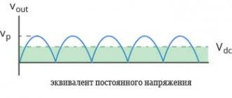
The reactances of inductance and capacitance are known to depend on the frequency of alternating current. As frequency increases, inductance reactance increases and capacitance reactance decreases. As the frequency decreases, on the contrary, the inductive reactance decreases and the capacitive reactance increases. Thus, for each circuit there is a certain resonance frequency at which the inductive and capacitive reactances are equal. At the moment of resonance, the amplitude of the alternating voltage on a parallel circuit sharply increases or the amplitude of the current on a series circuit sharply increases. Figure 2 shows a graph of voltage on a parallel circuit or current on a series circuit versus frequency:
At the resonance frequency these quantities have their maximum value. And the bandwidth of the circuit is determined at a level of 0.7 of the maximum amplitude that exists at the resonance frequency.
Now let's move on to practice. Suppose we need to make a parallel circuit that has a resonance at a frequency of 1 MHz. First of all, you need to make a preliminary calculation of such a circuit. That is, determine the required capacitance of the capacitor and the inductance of the coil. For preliminary calculation there is a simplified formula:
L=(159.1/F)2/C where: L – coil inductance in µH; C is the capacitance of the capacitor in pF; F – frequency in MHz
Let's set a frequency of 1 MHz and a capacitance of, for example, 1000 pF. We get:
L=(159.1/1)2 /1000 = 25 µH
Thus, if we want a circuit with a frequency of 1 MHz, then we need a 1000 pF capacitor and a 25 μH inductor. You can select a capacitor, but you need to make the inductance yourself.
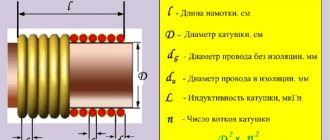
You can calculate the number of turns for a coil without a core using the following formula:
N=32 *√(L/D) where: N – required number of turns; L – specified inductance in µH; D is the diameter of the frame in mm on which the coil is supposed to be wound.
Suppose the frame diameter is 5 mm, then:
N=32*√(25/5) = 72 turns.
This formula is approximate; it does not take into account the coil’s own interturn capacitance. The formula serves to pre-calculate the coil parameters, which are then adjusted when tuning the circuit.
In amateur radio practice, coils with tuning ferrite cores having a length of 12-14 mm and a diameter of 2.5 - 3 mm are more often used. Such cores, for example, are used in the circuits of televisions and receivers. To preliminary calculate the number of turns for such a core, there is another approximate formula:
N=8.5*√L , substitute the values for our circuit N=8.5*√25 = 43 turns . That is, in this case, you will not need to wind 43 turns of wire onto the coil.
Current resonance
So, let's say we have driven our oscillatory circuit into resonance:
What will the resonant current Ires be equal to? We calculate according to Ohm's law:
Ires = Ugen /Rres, where Rres = L/CR.
But the funny thing is that during resonance in the circuit, our own circuit current Icon appears, which does not go beyond the boundaries of the circuit and remains only in the circuit itself! Since I have a hard time with mathematics, I will not give various mathematical calculations with derivatives and complex numbers and explain where the loop current comes from during resonance. That is why the resonance of a parallel oscillatory circuit is called current resonance .
Quality factor of parallel oscillatory circuit
By the way, this loop current will be much greater than the current that passes through the loop. And do you know how many times? That's right, Q times. Q is the quality factor ! In a parallel oscillatory circuit, it shows how many times the current strength in the circuit Icon is greater than the current strength in the common circuit Ires
Or the formula:
If we also add loss resistance here, the formula will take the following form:
Where
Q - quality factor
R - loss resistance on the coil, Ohm
C - capacity, F
L - inductance, H