To calculate the operating parameters of radio engineering devices and individual circuits, special techniques are used. After studying the relevant technologies, the result can be found out quickly, without complex practical experiments. Correct calculation of electrical circuits will be useful at the design stage and for carrying out repair work.
Problems involving the calculation of electrical circuits are solved using standard algorithms
Categories of elements and devices of the electrical circuit
For a conventional representation of a certain circuit, a special diagram is used. In addition to individual physical components, it contains information about the direction (strength) of currents, voltage levels and other information. A high-quality model shows real processes with high accuracy.
Electrical circuit components:
- source of direct or alternating current (E) – battery or generator, respectively;
- passive elements (R) – resistors;
- components with inductive (L) and capacitive (C) characteristics;
- connecting wires.
Typical names
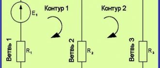
The figure shows:
- branches - sections of a circuit with one current;
- nodes – connection points of several branches;
- circuit - a closed path for current flow.
When solving practical problems, they figure out how to find out the current strength in individual branches. The obtained values are used to analyze electrical parameters. In particular, you can determine the voltage drop across the resistor and the power consumption of the connected load. When calculating AC circuits, it is necessary to take into account transient energy processes and the influence of frequency.
Potential Diagram Calculation
Content:
Potential diagram
Based on the results of calculating an electrical circuit for any of its circuits (branches), it is possible to construct a potential diagram - a graph of potential distributions in the circuit (branch). With the selected scale on the horizontal axis, the resistance values of the resistors (branches) of the circuit are located in the order (branches) located in the circuit, and along the vertical axis - the potential (branches) at the corresponding point in the circuit. You can start constructing a diagram from any point on the contour, equating its potential to an arbitrary value (for example, zero). The direction of traversal of the contour (branch) is chosen arbitrarily.
Example:
Let's construct a potential diagram for the external circuit of the electrical circuit, the diagram of which is shown in Fig. 2. When constructing a diagram, we use the current values calculated in example 2. We select the circuit bypass clockwise.
Let us equate the potential of point 4 to zero. The potential of point 3 is determined from the following considerations: when moving from point 4 to point 3, the direction of the circuit bypass coincides with the direction of the current 14, and since the current in the branch flows from a higher potential to a smaller one, the potential of point 3 will be lower than the potential of point 4 by the amount of voltage drop on resistor R4, therefore
As a result of the calculation, the potential of point 3 turned out to be higher than the potential of point 4, since the current direction chosen in the diagram is opposite to its true direction.
Similarly, we determine the potential of point 5: The potential of point I is higher than the potential of point 5 by the amount of EMF E1, since the direction of the circuit bypass coincides with the direction of the EMF (transition from the negative terminal of the EMF source to its positive terminal), therefore
The potentials of points 2 and 4 are determined in a similar way:
Calculation of the potential of point 4 was performed to verify the calculations. Total resistance of circuit resistors
Knowing the maximum and minimum values of the point potentials and the total resistance of the circuit resistors, you can select the scales for the potentials and resistance, and then construct a potential diagram (Fig. 3).
You might find these pages useful:
Using a potential diagram, you can determine the potential of any point on the circuit, equipotential points of the circuit, as well as the potential difference (voltage) between any points on the circuit. To determine the voltage, specified points are projected onto the ordinate; By multiplying the segment between the projections of the points by the voltage scale, we obtain the potential difference.
From the diagram you can determine the magnitude and direction of the current in any part of the circuit. The current is proportional to the tangent of the angle of inclination to the abscissa axis of the diagram segment corresponding to the section under consideration. The direction of the current is determined by the sign of the inclination angle; an angle measured clockwise is considered positive.
Calculation and construction of a potential diagram
Let us denote in the diagram Fig. 6 real directions of currents and EMF of the external circuit. Let us take the potential of point (1) equal to zero, i.e.
Let's calculate the potentials of all points, going around the contour clockwise (Fig. 6).
Comment. The current source is taken into account when calculating the current. Therefore, we do not include EMF in the diagram in Fig. 6.
Let's choose a scale for voltage and resistance:
Along the abscissa axis we plot the resistances along the contour, starting from point (1), and along the ordinate axis we plot the potentials.
Rice.
7. Potential diagram for a closed external loop of a given circuit Potential diagram
A potential diagram is a graph of the potential distribution along any section of a circuit or closed loop. Along the abscissa axis on it the resistances of the circuit sections are plotted one after another in the order in which they appear on the diagram, and along the ordinate axis the potentials of individual points of the circuit from zero are plotted. To determine potentials, the potential of one of the points is usually taken equal to zero (that is, this point is considered grounded).
Example of constructing a potential diagram
Payment terms
Construct a potential diagram for the circuit contour shown in Figure 4.5.2.1.
Circuit diagram
Figure 10.1.2.1 - Circuit diagram for constructing a potential diagram
Data for calculating the potential diagram
The currents are found in preliminary calculations of the entire circuit.
Potential Diagram Calculation
We ground point f, i.e. Let's take the potential of this point equal to zero, . When constructing a potential diagram, we place this point at the origin of coordinates (see Figure 10.1.5.1).
We go around the contour in a clockwise direction, starting from point f
We count the potentials of individual points of the circuit
Total loop resistance:
Building a Potential Diagram
Selecting the scales of resistances and potentials:
Based on the data obtained (section 10.1.4), we construct a potential diagram (see Figure 10.1.5.1) of the circuit shown in Figure 10.1.2.1.
The greater the current in a particular passive section of the circuit, the steeper the corresponding section of the diagram turns out. The tangents of the angles of inclination to the abscissa axis are proportional to the corresponding currents, for example,
A potential diagram allows you to find the voltage between any points on the circuit. This voltage is equal to the difference in ordinates of the corresponding points on the diagram. For example, (see Figure 10.1.5.1).
Figure 10.1.5.1 - Potential circuit diagram
The page -> solving problems in electrical engineering contains solutions to problems and assignments with solved examples on all topics of the theoretical foundations of electrical engineering (TOE).
Services:
Send tasks at any time of the day or night via WhatsApp.
Official website of Natalya Valerievna Brilyonova, teacher of the Department of Computer Science and Electronics of the Yekaterinburg State Institute.
All copyrights to the posted materials are reserved by the copyright holders of these materials. Any commercial and/or other use other than preliminary review of the materials on the site natalibrilenova.ru is prohibited. The publication and distribution of posted materials does not entail commercial and/or any other benefit.
The site is designed to facilitate the educational journey of full-time and part-time students on educational issues. Natalya Brilyonova does not offer or provide goods or services.
Calculation method according to Ohm's and Kirchhoff's laws
Before studying computing technologies, it is necessary to clarify the features of typical elements when connected to different power sources. At constant current, the inductive resistance can be neglected. A capacitor is equivalent to an open circuit. You should also take into account the following differences between different types of resistor connections:
- sequential - increases the total resistance;
- parallel - distributes currents over several branches, which improves conductivity.
Ohm's law for a circuit section
Differential automatic machine reliable protection of electrical circuits and people
A typical car battery produces a voltage of U = 12 V. An on-board or external ammeter will show the corresponding value when measured. Connecting the terminals with a wire is unacceptable, as this causes a short circuit. If the conductor is thin (< 1 mm), the high current density in the corresponding cross-section will quickly increase the temperature until thermal destruction of the material and breaking the circuit. This example demonstrates the functionality of a conventional fuse.
After connecting the load, you can check the voltage with a multimeter. The value of this parameter remains unchanged. If the resistance is known (example - R = 50 Ohms), applying Ohm's law ( I = U / R ) will help calculate the current:
I = 12/50 = 0.24 A.
Based on the calculated value, the power is quickly determined using the formula:
P = I2 *R = U2/ R = 0.0576 * 50 = 2.88 W.
For your information. The result of the calculation shown will be useful for finding a suitable resistor. You should make a reserve in the direction of increase. According to the standard of serial products, an element with a nameplate rated power of 5 W is suitable.
In practice, more complex problems have to be solved. So, with a significant line length, it is necessary to take into account the influence of the connecting branches of the circuit. Current will flow worse through a steel conductor compared to a copper analogue. Therefore, it is necessary to take into account the resistivity of the material in the calculation. A short wire can be excluded from the calculation. However, the load can have two elements. In any case, the overall figure is equivalent to a certain circuit resistance. With a series connection, Req = R1 + R2 +…+ Rn. This method is suitable if direct current is used.
Ohm's law for a complete circuit
To calculate such a circuit, you should add the internal resistance (Rin) of the source. How to find the current is shown by the following formula:
I = U/ (Req + Rin).
Instead of voltage (U), the standard designation for electromotive force (EMF) - E is often used in calculations.
Kirchhoff's first law
According to the classical formulation of this postulate, the algebraic sum of the currents that enter and exit one node is equal to zero:
I1 + I2 + … + In = 0.
This rule is valid for any connection point of the branches of an electrical circuit. It should be emphasized that in this case the characteristics of individual elements (passive, reactive) are not taken into account. You can ignore the polarity of power supplies connected to individual circuits.
To avoid confusion when working with large circuits, the following use of symbols for individual currents is assumed:
- incoming – positive (+I);
- outgoing ones are negative (-I).
Kirchhoff's second law
This rule establishes the total equality of current sources (EMF) that are included in the circuit under consideration. For clarity, you can see how the distribution of control parameters occurs when two resistors (R1 = 50 Ohm, R2 = 10 Ohm) are connected in series to a battery (Ub = 12 V). To check, measure the potential difference at the terminals of passive elements:
- UR1 = 10 V;
- UR1 = 2 V;
- Uaccb = 12 V = UR1 + UR2 = 10 + 2;
- the current in the circuit is determined according to Ohm's law: I = 12/(50+10) = 0.2 A;
- if necessary, calculate the power: P = I2 * R = 0.04 * (50+10) = 2.4 W.
Kirchhoff's second rule is valid for any combination of passive components in individual branches. It is often used for final verification. To clarify the correctness of the actions performed, add up the voltage drops on individual elements. We should not forget that additional sources of EMF make the result different from zero.
Electrical circuit conversion method
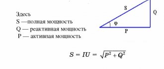
Power calculation
How to determine the current strength in individual circuits of complex circuits? To solve practical problems, it is not always necessary to clarify the electrical parameters of each element. To simplify calculations, special conversion techniques are used.
Calculation of a circuit with one power source
For a series connection, use the summation of electrical resistances discussed in the example:
Req = R1 + R2 + … + Rn.
The loop current is the same at any point in the circuit. You can check it at the break in the control section with a multimeter. However, on each individual element (with different ratings) the device will show a different voltage. According to Kirchhoff's second law, the result of the calculations can be clarified:
E = Ur1 + Ur2 + Urn.
Parallel connection of resistors, circuit design and formulas for calculations
In this version, in full accordance with Kirchhoff's first postulate, the currents are separated and connected at the input and output nodes. The direction shown in the diagram is chosen taking into account the polarity of the connected battery. According to the principles discussed above, the basic definition of equality of voltages on individual components of the circuit is preserved.
The following example demonstrates how to find the current in individual branches. The following initial values were accepted for the calculation:
- R1 = 10 Ohm;
- R2 = 20 Ohm;
- R3= 15 Ohm;
- U = 12 V.
The following algorithm will determine the characteristics of the circuit:
- basic formula for the three elements:
Rtotal = R1*R2*R3/(R1*R2 + R2*R3 + R1*R3.
- substituting the data, calculate Rtot = 10 * 20 * 15 / (10*20 + 20*15 +10*15) = 3000 / (200+300+150) = 4.615 Ohm;
- I = 12/ 4.615 ≈ 2.6 A;
- I1 = 12/10 = 1.2 A;
- I2 = 12/20 = 0.6 A;
- I3 = 12/15 = 0.8 A.
As in the previous example, it is recommended to check the result of the calculations. When connecting components in parallel, equality of the input currents and the total value must be maintained:
I = 1.2 + 0.6 + 0.8 = 2.6 A.
If a sinusoidal source signal is used, the calculations become more complex. When connecting a transformer to a single-phase 220V outlet, you will have to take into account losses (leakage) in idle mode. In this case, the inductive characteristics of the windings and the coupling (transformation) coefficient are essential. Electrical resistance (X L ) depends on the following parameters:
- signal frequency (f);
- inductance (L).
X L using the formula:
ХL = 2π * f * L.
To find the resistance of a capacitive load, the following expression is suitable:
Xc = 1/ 2π * f * C.
It should not be forgotten that in circuits with reactive components the phases of current and voltage are shifted.
Calculation of a branched electrical circuit with several power sources
Using the principles discussed, the characteristics of complex circuits are calculated. The following shows how to find the current in a circuit when there are two sources:
- indicate components and basic parameters in all circuits;
- make up equations for individual nodes: a) I1-I2-I3=0, b) I2-I4+I5=0, c) I4-I5+I6=0;
- in accordance with Kirchhoff’s second postulate, we can write the following expressions for the contours: I) E1=R1 (R01+R1)+I3*R3, II) 0=I2*R2+I4*R4+I6*R7+I3*R3, III ) -E2=-I5*(R02+R5+R6)-I4*R4;
- check: d) I3+I6-I1=0, external circuit E1-E2=I1*(r01+R1)+I2*R2-I5*(R02+R5+R6)+I6*R7.
Explanatory diagram for calculations with two sources
Electric field potential
An important property of the electric field, as a field that does not have vortices and is created by only stationary sources, is its potentiality
An electric field is called potential if the work done by a charge carrier in such a field when moving it along any closed contour is equal to zero.
The gravitational field of gravity is also potential
If you lift a load of a certain mass to a certain height, and then lower it back to the surface of the Earth, to the previous point, then the total mechanical work will also be zero.
Moreover, it does not matter at all what trajectory the load was lifted and lowered along. The source of such a gravitational field in this example is the Earth (a body with a mass many times greater than the mass of the lifted load).
Additional circuit calculation methods
Connecting an LED through a resistor and calculating it
Depending on the complexity of the device (electrical circuit), the optimal computing technology is selected.
Nodal voltage method
The basic principles of this method are based on Ohm's law and Kirchhoff's postulates. At the first stage, the potentials at each node are determined. Next, the currents in the individual branches are calculated taking into account the corresponding electrical resistances (individual components or equivalent values). The check is done according to the rules discussed.
Equivalent generator method
This technology is suitable for quickly calculating the current in one or more control branches.
Graphic explanation
In this technique, the general circuit is represented as a current source with a certain voltage and internal resistance. Next, calculations are performed along the control branch using a standard algorithm.