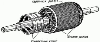
The AIR electric motor is a key link in the mechanism, ensuring its performance. Depending on what characteristics the engine offers, the entire device as a whole will act in the same way. Electric motors cover all spheres of human activity, first of all, they are widely in demand in industry.
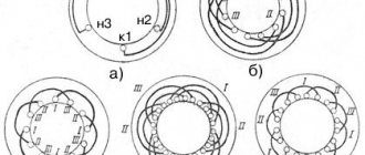
A synchronous electric motor is an alternating current device. The rotation frequency of the magnetic field that the armature creates is equal to the rotation frequency of the rotor.
The AIR asynchronous electric motor is a device that operates using alternating current, converting electrical energy into mechanical energy. In this device, the rotor rotation frequency is not equal to the rotation frequency of the magnetic field. Uninterrupted and reliable operation of an asynchronous motor is ensured by compliance with the necessary conditions: the altitude above sea level at which the motor operates should not exceed 1000 m; ambient temperature varies from -40 to +40 C; relative air humidity should not exceed 90% (at a temperature of +25 C), air dust content for closed engines is less than 10 mg/m3, 2 mg/m3 for protected ones.
For non-standard conditions, special engines are produced.
Explosion-proof asynchronous electric motors eliminate the possibility of explosion by enclosing the motor components that directly interact with electricity in an explosion-proof enclosure. Such a shell withstands the pressure of the explosion inside, preventing it from escaping into the environment.
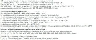
General scheme for marking electric motors
1. Series designation:
AIR, A, 4A, 5A, AD, 7AVER - general industrial electric motors with power adjustment according to GOST 51689-2000
AIS, 6A, IMM, RA, AIS - general industrial electric motors with power binding according to the European standard DIN (CENELEC)
AIM, AIML, VA, AV, VAO2, 1VAO, 3V - explosion-proof electric motors
AIU, VRP, AVR, 3AVR, VR - explosion-proof mining electric motors
A4, DAZO4, AOM, DAV, AO4 - high-voltage electric motors
2. Sign of modification:
M - modernized electric motor (for example: AD M 63A2U3)
K- electric motor with a wound rotor (for example: 5 AN K 280A6)
X- electric motor with aluminum frame (for example: 5AM X 180M2U3)
E - single-phase electric motor 220V (for example: AIR E 80S2U3)
N - protected electric motor with self-ventilation (for example: 5A N 200M2U3)
F - protected electric motor with forced cooling
S - electric motor with increased slip (for example: AIR S 180M4U3)
V - built-in electric motor (for example: ADM V 63V2U3)
R - electric motor with increased starting torque (for example: AIR R 180S4У3)
P- electric motor for driving a fan in poultry farms (“poultry house”)
3. Dimensions (height of the shaft rotation axis above the mounting surface) mm:
50, 56, 63, 71, 80, 90, 100, 112, 132, 160, 180, 200, 225, 250, 280, 315, 355, 400
4. Installation dimensions or core length:
A, B - core length option
S, M, L - variant of core length and installation dimensions along the length of the bed
X, XK, Y, YK - stator core length option for high-voltage motors
5. Number of poles:
2 (3000 rpm), 4 (1500 rpm), 6 (1000 rpm), 8 (750 rpm), 10 (600 rpm), 12 (500 rpm)
4/2, 6/4, 8/6, 12/4, 12/6, 6/4/2, 8/6/4, etc. — multi-speed electric motors
6. Sign of design modification:
B - electric motor with built-in winding temperature protection sensor
B1 - electric motor with temperature protection sensor for windings and bearing units
B2 - electric motor with winding temperature protection sensor and heater
E - electric motor with built-in electromagnetic brake (for example: AIR80A2 E U3)
E2 - electric motor with built-in brake and release handle
P - electric motor with increased accuracy of installation dimensions
Zh - electric motor for driving monoblock pumps (for example: AIR80A2 ZH U2)
N - low noise electric motor (for example: 5AN180S4/16 N LBUHL4)
L - electric motor for driving elevators (for example: 5AN180S4/16N L BUHL4)
C - electric motor for driving oil pumping units (for example: AIR180S4 S NU1)
Tr - electric motor for axial fans in transformer cooling systems
P3 - electric motor for gearmotors
7. Climatic version (GOST 15150-69)
U - for a macroclimatic region with a temperate climate
UHL - for macroclimatic regions with temperate and cold climates
HL - for a macroclimatic region with a cold climate
T - for macroclimatic regions with both dry and humid tropical climates
M - for the macroclimatic region of the region with a moderately cold maritime climate
О - for all macroclimatic regions on land, except for very cold ones (general climatic version)
B - for all macroclimatic regions on land and sea, except very cold (all-climatic version)
8. Placement categories (GOST 15150-69)
1- for outdoor use
2- for use under canopy, in tents, body trailers
3— for use in rooms without controlled climatic conditions
4— for use in rooms with artificially controlled climatic conditions
5- for use in rooms with high humidity
AIR marking
A general view of the marking is shown in the figure next to it.
Let's consider each element sequentially.
- AIR
is an abbreviation, the decoding is indicated in the picture and does not require additional description; - Heights of rotation
- h indicator shown on the size chart; - Installation dimensions
- dimensions along the length of the housing (S - small, M - medium, L - large) + sometimes an additional symbol along the length of the shaft core (A or B). A detailed correspondence of codes to the dimensions of each specific model is presented in the document attached to the article “Installation dimensions (overall and connecting) AIR.pdf”; - The number of poles
are specific numbers, which from a practical point of view mainly show the synchronous speed of rotation of the magnetic field, which is also related to the frequency of the electrical network. The more poles, the lower the efficiency and power factor, as well as the lower the speed. For the equipment in question, the correspondence is as follows:
- 2 pole pairs = 3000 rpm;
- 4 pairs = 1500 rpm;
- 6 pairs = 1000 rpm;
- 8 pairs = 750 rpm;
Mounting design
Let's look at each number separately.
- The first number
is the mounting method:
- IM 10XX - paws;
- IM 20XX - combined (feet/flange);
- IM 30XX - flange;
is the mounting location. For these engines it is always “0”, meaning “mounted to the body”.
is the number of working ends of the shaft:
- With one shaft end - 1;
- With two shaft ends - 2;
- The third number
is determined by the location of the engine and the direction of the shaft axis.
Below is a table showing the possible options, but there is also a special meaning - “ 8
”, meaning universal execution, i.e. The motor can be positioned in any direction of the shaft axis!
The table is also attached as a file to the article for more careful study, if necessary.
Permissible operating temperatures for basic climatic versions
| Climatic performance | Accommodation categories | Air temperature during operation, C | |||
| Working | Limit working | ||||
| top | lower | top | lower | ||
| U, TU | 1,2,3 | +40 | -45 | +45 | -45 |
| 5 | +35 | -5 | +35 | -5 | |
| UHL | 1,2,3 | +40 | -60 | +45 | -70 |
| 5 | +35 | -10 | +35 | -10 | |
| T,TS | 1,2,3 | +50 | -10 | +60 | -10 |
| 5 | +35 | +1 | +35 | +1 | |
Electric motors of the AIR series, information in the labeling
Asynchronous electric motors (hereinafter referred to as IM)
) of this unified series (AI) replaced electric machines of earlier series 4A, 4AM and their modifications.
By analogy with the latter, the AI series includes electric motors with a power range of 0.06-315 kW, a rotation axis height (distance from the lower surface of the paws to the center of the shaft) of 50-355 mm and having a range of nominal rotation speeds of 750-3000 rpm /min.
Marking
. These markings contain information about the nominal values of various technical parameters, design, and method of installation of electric motors.
1
— a unified series
of IM
(A - asynchronous, I - a unified series
of IM
within the framework of Interelectro);
2
— determination of a system option for linking the power of an electric machine to installation and connection dimensions (C or P - in accordance with the P 51689 standard or in accordance with the CENELEC-DOCUMENT standards, Doc. 28/64 and DIN 42673, DIN 42677);
3
- letter modification index, the brand may contain more than one designation (C - having increased slip, XP - characterized by increased starting torque);
4
- engine size or height of the rotation axis (distance from the rotation axis - the center of the shaft to its supporting plane - the lower surface of the paws). GOST 13267-73 defines a standard range of rotation height values from 25 to 1000 mm.
For flanged IM
and machines with special types of fastening, it is customary to take the conventional value of the height of rotation (up to its conventional reference plane), rounded down to the nearest value determined by the standard mentioned above;
5
- letter index of the installation size along the length of the bed (S, M or L - an abbreviation for Short, Medium and Long);
6
– length of the stator core (A, B, C, D), in the absence of a letter it should be understood that for a given installation size there is only one length of the core;
7
– number of poles of the electric machine (2, 4, 6, 8, 4/2, 6/4, 8/4);
8
— engine design modification index:
B
— the modification provides temperature protection,
P
— having increased accuracy of installation dimensions,
E/E2
— equipped with el.
magnetic brake/el. magnetic and hand brake, F
– motors designed for monoblock pumps;
RZ
– for use in geared motors,
X2
– chemically resistant design;
9
— climatic performance index (
U
,
HL
,
UHL
,
TV
,
TS
,
T
,
TM
,
M
,
O
,
V
) and placement category (from 1 to 5), defined in GOST 15150.
Operating air humidity values for basic climate versions
| Climatic performance | Accommodation category | Relative humidity | Abs. humidity, average annual value, g*m3 | |
| Average annual value | Upper value | |||
| U, UHL, HL, TU | 1, 2 | 75% at 15ºС | 100% at 25ºС | 11 |
| 3 | 75% at 15ºС | 98% at 25ºС | 11 | |
| T, TV, O, M, OM | 5 | 90% at 15ºС | 100% at 25ºС | 13 |
| 1, 2, 5 | 80% at 27ºС | 100% at 35ºС | 20 | |
Decoding the marking of AIR electric motors
- A - asynchronous
- I - unified series (I - Interelectro);
- X - Linking capacities to installation and connection dimensions (P - according to RS 3031-71, C - according to CENELEK document 28/64);
- X - P - with increased starting torque, - C - with increased slip;
- XXX—dimension, mm;
- X — installation dimension along the length of the frame (S, M, L);
- X is the length of the stator core (A or B, the absence of a letter means only one length of the core - the first);
- X - number of poles: 2, 4, 6, 8;
- X - additional letters for modifications of the electric motor (B - with built-in temperature protection);
- P - with increased accuracy in installation dimensions;
- X2 - chemically resistant; C - agricultural);
- XX - climatic modification of the electric motor (U, T, HL) and placement category (1, 2, 3, 4, 5).
Terms of Use:
At ambient temperatures from - 40°C to + 40°C.
Relative air humidity at a temperature of plus 25°C is up to 98% for versions U2, U1.
Air dust content for electric motors with degree of protection 1Р44 is no more than 10 mg/m3, 1Р23 is no more than 2 mg/m3.
The environment is not explosive, does not contain conductive dust, aggressive gases and vapors in concentrations
- destroying metal and insulation (except for chemically resistant versions). The sound level at a distance of 1 m from the main motor housing at idle is on average from 51 to 85 dBA
- depending on size and rotation speed.
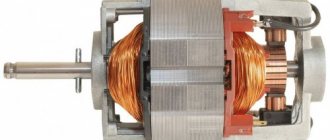
Design: AIR electric motors are manufactured in two versions:
- in aluminum (cast iron panels, aluminum frame)
- in cast iron (both the panels and the frame are made of cast iron).
Design and installation method (according to GOST 2479-79). Symbol structure:
- X - Latin letters IM or M
- X - Design (one digit)
- XX — Installation method (two digits)
- X - Shaft end design (one digit)
According to the installation method, the production of AIR engines occurs in the following versions (1st digit):
- IM1 - on feet with bearing shields;
- IM2 - on feet with bearing shields and a flange on the drive side;
- IMZ - without paws with bearing shields and a flange on the drive side.
Shaft end symbols (4th digit):
- 1 - with one cylindrical shaft end;
- 2- with two cylindrical shaft ends.
Mounting version IMxxxx
The mounting design of the AIR electric motor is designated by the Latin letters IM and four numbers after them. Also sometimes found is a designation according to the international standard IEC60034-7 (code I), including the Latin letters IM, the Latin letter B or V and 1 to 2 digits.
The first number is the design of the electric motor
1— electric motor on feet with bearing shields
2— electric motor on feet with bearing shields and a flange on one shield
3— electric motor without feet with bearing shields and a flange on one shield
The second and third numbers indicate the spatial method of mounting the electric motor. If the third digit is “8”, for example IM1081, then such an electric motor can be mounted in any position.
The fourth digit is the design of the shaft end
1- electric motor with one cylindrical shaft end
2- electric motor with two cylindrical shaft ends
3- electric motor with one conical shaft end
4- electric motor with two conical shaft ends
General industrial electric motors AIR series
Electric motors of the AIR series are used in the industrial sector to convert electrical energy into mechanical energy. The operating principle is based on electromagnetic induction. Various modifications of three-phase asynchronous motors have a very wide scope of application:
- mechanical engineering and machine tool industries;
- agricultural equipment;
- woodworking;
- pumping and ventilation equipment;
- lifts and conveyor belts.
The special purpose that electric motors of the AIR series may have is indicated in additional designations. Abbreviations indicate recommendations on operating conditions that affect the design features of fasteners, the presence of manual braking adjustment, installation dimensions that are close to absolute accuracy, the level of chemical protection, etc. It is worth considering that special-purpose mechanisms may have an increased level of performance (including and sound effects).
Depending on the purpose, asynchronous electric motors can correspond to one of the types of climatic modification: U2; U3; T2; UHL4. Asynchronous electric motors are produced with design differences that determine the degree of protection (IP55; IP54) in versions with stationary and rotating magnetic fields based on operation in conditions s1.
The degree of protection of the engine from contact with moving parts, conductive elements and from the penetration of foreign objects or moisture into the engine can affect the design features of the protective casing. There are completely open motors that are operated in special rooms without exposure to extraneous factors (including the presence of people during operation), protected by a current-insulating casing and equipped from drops of moisture (strictly vertical direction of flow). The highest degree of protection is to protect a special-purpose mechanism from dust by installing a dust-proof membrane under the outer casing.
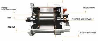
AIR - motors with a squirrel-cage rotor type are distinguished by their relative simplicity of design. Stationary contacts ensure reliability during operation. According to the installation method, electric motors of the AIR series are divided into units for vertical/horizontal or built-in installation. Each type of fastening is indicated by corresponding markings on the electric motor itself.
For horizontal installation:
- M101 - on feet to the frame.
- M201 - for suspended mounting on a frame.
- M301 - motor with an annular flange for installation on a bearing shield.
For vertical installation:
- M302 - motor for mounting with a flange on a bearing shield with the working end of the shaft in a “down” position; M202 - modification for flange mounting on a panel (+ paws on the frame); M203 - similar to M202 only with an “up” operating position.
- M303 - a modification of the fastening similar to M302 with fastening the working end of the shaft “up”. M102 - mounting option M303 with foot mounting; M103 - identical fastener M102 with the working end in the “up” position.
Decoding the symbols of AIR engines
- “A” - asynchronous motor type.
- “I” is the degree of protection from external factors.
- “P” is the relationship between engine power and installation dimensions.
- Digital indicators indicate the height of rotation of the axis.
- “S” is the size of the installation according to the length of the frame.
- The next numerical designation is the number of poles.
- “U” - climatic version.
- “Z” – category of electric motor placement.
Main technical characteristics of electric motors of the AIR series
Power and installation dimensions (from the base platform to the center of the shaft) are determined by GOST 51689-2000. The resistance of the insulation to heat must comply with the requirements of GOST 8865-93 (class “F”). The level of noise generation (in idle mode) is class 2 according to GOST 16372-93. Standard engine cooling design according to scheme 1C-0151.
Protection degree IPxx (GOST 17494-87)
The first digit is protection against penetration of solid bodies.
0- unprotected electric motor
1- electric motor protected from solid bodies with a diameter of more than 50 mm
2- electric motor protected from solid bodies with a diameter of more than 12 mm
3- electric motor protected from solid bodies with a diameter of more than 2.5 mm
4- electric motor protected from solid bodies with a diameter of more than 1.0 mm
5- electric motor protected from dust
The second number is protection against water penetration
0- unprotected electric motor
1- electric motor protected from vertically dripping water
2— electric motor protected from falling drops at an angle of up to 15º to the vertical
3— electric motor, protected from falling drops at an angle of up to 60º to the vertical (from rain)
4- electric motor protected from water sprayed from all directions
5- electric motor protected from water jets from all directions.