Device
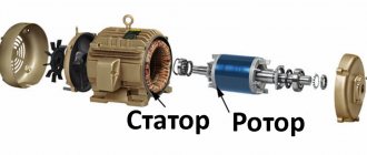
Structurally, a synchronous electric motor consists of a fixed element, a moving part, windings for various purposes, and can be equipped with a commutator unit. Next, we will consider each component of a synchronous unit in more detail using a working example (Figure 1).
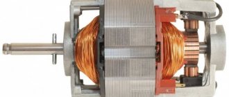
Rice. 1. Design of a synchronous electric motor
- Stator or armature - made of electrical steel, monolithic or assembled from laminated iron. Designed to accommodate the working winding, it conducts power lines of the electromagnetic field formed by flowing currents.
- The winding on the stator is made of copper conductors; depending on the type of stator of the synchronous electric motor, it can be made using various methods, methods of winding and arrangement of conductors. It is used to supply power voltage and generate a working magnetic flux.
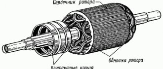
- Rotor with field winding - designed to interact with the magnetic field of the stator. As a result of applying voltage to the excitation winding, its own magnetic field is created in the electric motor rotor, which sets the state of the rotating element.
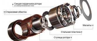
- Shaft - used to transmit rotational force from the electric motor to the load connected to it. In most cases, this is the base on which the charge or rotor poles, bearings, rings, plates and other auxiliary elements are mounted.
- Slip rings are used to supply power to the rotor windings, but are not installed in all models of synchronous units. Power is supplied through a special AC-DC voltage converter.
- Housing - designed to protect against external factors, provides the synchronous motor with sufficient strength and tightness, depending on its operating conditions.
Excitation methods
The operation of a rotary synchronous engine depends on the activation of a source of magnetomotive force. This could be a generator in which a magnetic field meshes with the stator windings and imparts an electric force to them. The motor interacts with the magnetic fields of its constituent elements.
There are two methods of excitation - electromagnetic or with a winding, and with permanent magnets. The first ones are quite widespread. In this scheme, when direct current passes through the winding, a moving magnetic force appears, driving a magnetic field in the mechanism system.
In the recent past, stimulation of synchronous units was carried out by direct current generators with a self-excitation circuit or with an independent type of excitation. In the latter option, current is supplied to the exciting winding. An additional AC compensator operating in parallel was used.
Self-excitation, characteristic of synchronous engines and hydrogenerators, is understood as the process of converting direct current energy, which is necessary for stimulation, into direct current. This happens through a step-down transformer and a special converter.
In generators with self-exciting properties, the winding of the poles is powered by electricity generated by the device itself. That is, there is no need to organize a separate energy source. The following types of self-excitation are distinguished, depending on the winding switching algorithm:
- Parallel - the armature current of the device is distributed between the load current and the excitation current. The latter is usually small, and then the generator does not experience high loads. Typically, these units are used as power supplies on cars, ships or aircraft.
- Consistent. The stator winding and the exciter winding are connected to each other in a series circuit. Such devices are rarely used.
- Mixed. These units have excitation windings that have concordant and counter-connected excitation windings. The voltage remains the same as the traction increases or decreases. The devices are used when sufficient stability of the power supply is required when the load changes.
In the modern world, in synchronous motors, tristor devices are responsible for excitation, which are connected to the alternating current network and automatically controlled by the exciting current in different operating modes of the installation. This is the most reliable method, because they have high efficiency. Factories usually produce tristors for various voltages with a possible DC current of 320 amperes.
Low-power “synchronous machines” use a permanent magnet excitation circuit. In this case, there are permanent magnets on the inductor, which makes it possible not to use an exciting winding. As a result, the car frame becomes simpler, more reliable and more economical. But due to a shortage of materials, it is necessary to use devices whose power barely reaches several kilowatts.
Principle of operation
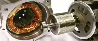
The operation of a synchronous electric motor is based on the interaction of the magnetic flux generated by the working windings with a constant magnetic flux. The most common model of a synchronous electric machine is the version with a working winding on the stator and an excitation winding on the rotor.
Rice. 2. Operating principle of a synchronous electric motor
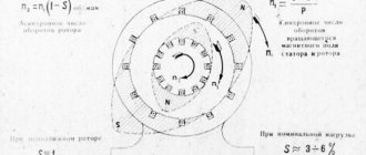
As you can see in Figure 2 above, three-phase voltage from the network is supplied to the stator winding, which forms an alternating magnetic field. A constant voltage is applied to the rotor windings of the electric motor, which induces the same constant magnetic flux at the poles. For clarity, let’s consider the process using a simplified model of a synchronous unit (Figure 3).
Rice. 3. The principle of flow formation in a synchronous electric machine
When power is supplied to the phase turns of the stator of the electric motor, the first peak of the current amplitude and mutual inductance EMF occurs in phase A, then B and phase C.
The graph shows the frequency of alternation of curves depending on time:
- at point 1, the maximum EMF EA forms the maximum flux, and the electromotive forces of the EB and EC phases are equal to each other and opposite in sign, they complement the resulting force.
- at point 2, the EMF EB reaches its peak, and the electromotive forces of the EA and EC phases become equal to each other and opposite in sign, they complement the resulting force, as a result of which the magnetic field performs a rotational motion.
- at point 3, the maximum falls on the emf EC, and the electromotive forces of the EB and EA phases together complement the resulting force and again shift the field vector clockwise.
The rotation of the stator field occurs over a period, and due to the fact that the rotor has its own electromagnetic force that is constant over time, it synchronously follows the movement of the alternating magnetic field, rotating around a given axis. As a result of such rotation, synchronous movement of the rotor occurs following a change in the amplitude of the EMF in the turns of the working windings; due to this phenomenon, the electric motor is called synchronous. The presence of a separate power supply was also reflected in the schematic designation of such electrical machines (Figure 4) in accordance with GOST 2.722-68.
Rice. 4. Schematic designation of a synchronous electric motor
Starting a synchronous motor
The peculiarity of this type of electric machine is that you cannot simply connect it to the network and wait for it to start. In addition to the fact that for an LED to operate, it requires not only an excitation current source, it also has a rather complex starting circuit.
Starting occurs like an asynchronous motor, and to create a starting torque, in addition to the excitation winding, an additional short-circuited “squirrel cage” winding is placed on the rotor. It is also called a “damping” winding because it increases stability under sudden overloads.
There is no excitation current in the rotor winding at start-up, and when it accelerates to a subsynchronous speed (3-5% less than synchronous), an excitation current is supplied, after which it and the stator current oscillate, the engine enters synchronism and enters operating mode.
To limit the starting currents of powerful machines, sometimes the voltage at the terminals of the stator windings is reduced by connecting an autotransformer or resistors in series.
While the synchronous machine is started in asynchronous mode, resistors are connected to the excitation winding, the resistance of which exceeds the resistance of the winding itself by 5 - 10 times. This is necessary so that the pulsating magnetic flux arising under the influence of currents induced in the winding during startup does not slow down the acceleration, and also so as not to damage the windings due to the EMF induced in it.
Difference from an asynchronous motor
The main difference between a synchronous electric motor and an asynchronous one is the principle of converting electrical energy into mechanical rotation. In a synchronous electric motor, the rotor rotation process is identical to the rotation of the working electromagnetic field generated by a three-phase network. But in an asynchronous one, the working field independently induces an EMF in the rotor, which then generates its own flow of mutual induction and causes the shaft to rotate. As a result, asynchronous electric machines receive a difference in the rotation of the working field and the load on the shaft, which is expressed by a physical quantity - slip.
In operation are classic models of asynchronous electric motors with a squirrel-cage rotor:
- do not tolerate overloads well;
- have difficulty starting with significant force;
- change the rotation speed depending on the load of the working body.
To some extent, these shortcomings are overcome by an asynchronous motor with a wound rotor, but only a synchronous unit can completely get rid of these shortcomings.
Rice. 5. Difference between an asynchronous and a synchronous electric motor
Varieties
In modern industry and household appliances, synchronous electric motors are used to solve a wide variety of problems. As a result, their design features also differ significantly. In practice, there are several criteria by which types of synchronous units are divided. In accordance with GOST 16264.2-85 they can be divided according to the following technical characteristics:
- supply voltage;
- operating voltage frequency;
- number of revolutions.
Depending on the method of obtaining the rotor field, the following types of synchronous electric motors are distinguished:
- With an excitation winding on the rotor - the synchronizing force is created by supplying power from the converter.
- With a magnetic rotor - a permanent magnet is installed on the shaft, performing the same functions as the field winding, but without the need for recharge (see Figure 6).
Rice.
6. Synchronous electric motor with permanent magnets With a reluctance rotor - the design is made in such a way that refraction of magnetic lines occurs in its core, causing the entire structure to move (see Figure 7). Under the influence of a force field, the transverse and longitudinal components in the rotor are not equal, due to which the plates rotate following the field.
Rice. 7. Example of a jet rotor
Depending on the presence of poles, all synchronous electric motors can be divided into:
- salient-pole - the design clearly shows separate poles with windings, used for low speeds;
- non-salient pole - the pole is not highlighted, such models are installed for high speeds;
Depending on the location of the working windings, a distinction is made between direct (on the stator) and reverse (working windings on the rotor).
Mechanical and angular characteristics
Due to the inherent features of a synchronous motor, the value of its torque does not depend on the rotation speed. This property of the drive determines its purpose and scope of application. The technical qualities of drive equipment for configuring an electric drive are assessed by the dependence of the motor speed on the electromagnetic torque developed by it. This relationship is known as the mechanical characteristic of a synchronous motor. It can be static or dynamic. The first shows the behavior of the LED in a stable operating mode. The second characterizes his work during the transition period.
The quality of mechanical characteristics is assessed by rigidity. With respect to this parameter, all characteristics are divided into ideally hard, hard and soft. Due to the fact that the rotor speed of a synchronous motor does not change under load, this type of electric motor has an ideally rigid characteristic, which is expressed by the formula:
n = 60*f1/p,
where f1
– stator current frequency;
p –
number of pole pairs of the stator winding.
But the dependence n = f (M)
does not reflect the full behavior of the motor, in which, as the load increases, the axes of the inductor and armature field shift. Each load corresponds to a certain angle between their axes. Angular characteristic equation:
Mem = Mmax*sin θ
This formula expresses the approximate dependence of the torque on the shaft on the rotor departure angle. In real conditions, the maximum torque corresponds to an angle slightly less than 90˚. In this case, the overload capacity of the SD is equal to: λm = Мmax/MN = 2–3.
Operating modes
Most electric machines have a reversible function, and synchronous units are no exception. They can also be used as an electric drive or as a generator to produce electricity. Both modes differ in the way they influence the electric machine - applying voltage to the working windings or driving the rotor due to mechanical force.
Generator mode
Synchronous generators are used to produce electricity into the network. In most cases, electric machines with phase windings on the stator are used for this purpose, which significantly simplifies the process of collecting power and its further transfer to the network. Physically, generation occurs when exposed to the electromagnetic field of the excitation winding of a synchronous generator with stator windings. The power lines alternately cross the phase turns and induce mutual induction emf in them, as a result of which voltage appears at the terminal terminals.
The frequency of the resulting voltage directly depends on the shaft rotation speed and is calculated by the formula:
f = (n*p)/60 ,
where n is the shaft rotation speed, measured in revolutions per minute, p is the number of pole pairs.
Synchronous compensator
Due to the physical characteristics of the synchronous electric motor, when the device is idling, it consumes reactive power from the network, which can significantly improve the cosφ of the system, practically bringing it closer to 1. In practice, the synchronous compensator mode is used both to improve the power factor and to stabilize the network voltage parameters.
Motor mode
In a synchronous machine, the motor mode is carried out when a three-phase operating voltage is supplied to the armature windings. After which the electromagnetic field of the armature begins to push the magnetic field of the rotor, and the shaft begins to rotate. However, in practice, the propulsion mode is not so simple, since powerful units cannot independently gain the necessary speed resource. Therefore, during startup, special methods and connection diagrams are used.
The working process
A synchronous motor is an electrical device that operates on the basis of the law of electromagnetic induction. The operating principle and design of the LED are based on the practical application of this physical phenomenon. The magnetic field is created by a three-phase winding placed in the slots of the stator package, similar to the circuit of an asynchronous machine. The rotor contains an excitation winding powered by direct current. Power is supplied to it through brushes and rings. The direct current flowing through the exciting winding interacts with the rotating field of the inductor, which causes circular motion of the shaft. Torque depends on the current load and is independent of speed. That is why this type of drive is called a synchronous electric motor, that is, the speed of the armature is equal to the speed of the inductor field.
Once started, the AC synchronous motor rotates simultaneously with the magnetic flux. The SD cannot be started using only the mains supply. This is explained by the inertia of the rotor unit and the high speed of the rotating field. The switching circuit of a low-power machine involves the use of starting (damper) windings, with which it operates as a synchronous motor with a squirrel-cage rotor (that is, an asynchronous start is realized). In the case of powerful electric drives, the start is carried out by an auxiliary electric motor or frequency converter.
The most widespread is asynchronous starting, which involves the installation of an additional short-circuit winding. In this case, a synchronous motor with a squirrel-cage rotor is started similarly to an asynchronous electric motor. As a result of such actions, the rotor mechanism accelerates to the speed of the rotating magnetic flux. If a synchronous motor is loaded, the distance between the armature and field poles increases. As a result, the anchor mechanism lags behind the load angle, which corresponds to the lag from its position at idle.
The design and operating principle of a synchronous motor provide for operation of the drive at a constant speed, which does not depend on the load. The LED is not designed for a load whose value exceeds the starting power between the rotor mechanism and the magnetic flux. Otherwise, the synchronism is interrupted and the operation of the synchronous motor stops.
Starting methods and connection diagrams
To start a synchronous electric motor, an additional field is required, independent of the network influence. At the same time, at the starting stage, the start-up is an asynchronous process until the unit reaches synchronous speed.
Rice. 8. Synchronous motor starting circuit
When voltage is applied to the armature, a current occurs in its windings and an EMF is generated in the rotor iron, which ensures asynchronous movement until the field windings are powered.
Another common starting option is the use of additional generators, which can be located on the shaft or installed separately. This method provides additional starting force due to external torque.
Rice. 9. Generator method of starting a synchronous motor
As you can see in Figure 9, the initial rotation of the motor M is carried out by the generator G, which is designed to bring the device to a subsynchronous speed. Then the generator is removed from the operating circuit by opening the KM contacts or automatically when the operating characteristics are set. Further maintenance of the synchronous mode occurs due to the supply of constant voltage to the excitation winding.
In addition, in practice a starting circuit with semiconductor converters is used. Figure 10 shows a thyristor converter method with the installation of rotating rectifiers.
Rice. 10. Thyristor circuit for starting a synchronous motor
In the first case, the start of a synchronous electric motor is characterized by zero voltage from the converter UD. Due to the sliding EMF through the zener diodes VD, the thyristors VS are opened. A resistor R is introduced into the excitation winding circuit, designed to prevent insulation breakdown. As the electric motor accelerates, the sliding EMF will decrease proportionally and the zener diodes VD will lock, the circuit will be blocked, and the excitation winding will receive constant voltage power through UD.
Application
The scope of application of synchronous electrical machines covers the production of electrical energy at power plants. By type, generators are divided into turbine, diesel and hydraulic, depending on the method of driving them into rotation.
They are also used as electric motors, which can withstand significant overloads during operation. Such motors are installed on fans, compressors, power units and other equipment. A separate category of electric motors is used in precision equipment, where synchronization of operations and processes is important.
Advantages and disadvantages
The advantages of such an electric motor include:
- high cosφ, approaching 1 in value, which is significantly superior to asynchronous electric motors;
- higher mechanical strength due to the design features of the electric motor;
- the dependence of torque on voltage is linear, not quadratic, so the oscillations of the electric motor are proportionally reduced;
- there is a constant speed on the electric motor shaft, independent of the applied load;
- can be used to reduce the reactive component in the network.
Among the disadvantages of synchronous electric motors are:
- complex design;
- more complex launch;
- the need to use auxiliary devices and blocks;
- such electric motors are more difficult to regulate in terms of speed;
- repairs and maintenance will also cost more than asynchronous electric motors.
Advantages and disadvantages
An electric machine with a synchronous circuit has the following advantages:
- High productivity ratios
- The use of "synchronous" in production to increase the power index
- Increased efficiency, which is several times greater than that of an asynchronous machine
- Good degree of strength
- Lack of sensitivity to changes in voltage in the electrical network
But, despite the obvious advantages, there are also a number of disadvantages. This is the complexity of the starting design and the high price of the unit. Synchronous motors are used to start mechanisms that do not require a change in speed.
But powering the rotor winding requires a direct current source, and the inductor rotation frequency can be adjusted using transformers, and this is also expensive. It turns out that “synchronous devices” are used when it is not necessary to frequently turn off or turn on a particular device.