March 22, 2022 kmelectric equipment and faults
Electricity today is one of the most popular sources of energy. To use it, special mechanisms are used that are capable of converting current into rotational force.
One of the most popular systems are commutator motors. They are found everywhere, as they are distinguished by their simplicity and functionality.
Classifications
By energy source
Engines can use the following types of energy sources:
- electrical; DC (DC motor);
- AC (synchronous and asynchronous);
By type of movement
The engines can convert the resulting energy to the following types of movement:
- rotational motion of solid bodies;
- translational motion of solid bodies;
- reciprocating motion of solid bodies;
- jet movement;
- other types of movement.
Electric motors that provide translational and/or reciprocating motion of a solid body;
- linear;
- induction;
- piezoelectric.
Some types of electric rocket engines:
- ion engines;
- stationary plasma engines;
- motors with anode layer;
- radioionization engines;
- colloid engines;
- electromagnetic motors, etc.
By device
External combustion engines are a class of engines where the heat source or fuel combustion process is separated from the working fluid:
- piston steam engines;
- steam turbines;
- Stirling engines;
- steam engine.
Internal combustion engines are a class of engines in which the formation of a working fluid and the supply of heat to it are combined in one process and occur in one technological volume:
- engines with hermetically sealed working chambers (piston and rotary internal combustion engines);
- engines with chambers from which the working fluid has free access to the atmosphere (gas turbines).
According to the type of movement of the main working body, internal combustion engines with lockable working chambers are divided into internal combustion engines with reciprocating motion (piston) (divided into trunk and crosshead) and internal combustion engines with rotational motion (rotary), which, according to the types of rotational motion, are divided into 7 different types of structures. Based on the type of ignition of the working mixture, internal combustion engines with hermetically sealed chambers are divided into engines with forced electric ignition (glow or spark) and engines with compression ignition of the working mixture (diesel).
According to the type of mixture formation, internal combustion engines are divided into: with external mixture formation (carburetor) and with direct fuel injection into the cylinders or intake manifold (injection). Based on the type of fuel used, internal combustion engines are divided into those running on gasoline, liquefied or compressed natural gas, alcohol (methanol), etc.
Jet engines
Air-jet engines:
- ramjet engines (ramjet engines);
- pulsed jet engines (PuVRD);
- gas turbine engines: turbojet engines (TRD);
- dual-circuit turbofan engines;
- turboprop (TVD);
- turbofan high-pressure engines;
Rocket engines
- liquid rocket engines;
- solid propellant rocket engines;
- nuclear rocket engines;
- some types of electric rocket engines.
By application
Due to fundamentally different requirements for an engine depending on its purpose, engines identical in operating principle can be called “ship”, “aviation”, “automobile” and the like.
The category “Engines” in patent science is one of the most actively replenished. Between 20 and 50 applications in this class are submitted per year worldwide. Some of them are distinguished by their fundamental novelty, some by a new ratio of known elements. Engines that are new in design appear very rarely.
Single-phase and three-phase asynchronous motors
We agreed - three-phase commutator motors are difficult to obtain; the current section deals with asynchronous machines. We list the varieties:
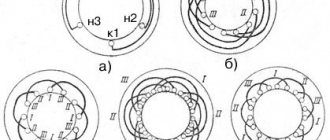
- Three-phase asynchronous motors are equipped with a number of outputs from three to six working windings minus various fuses, internal relays, and various sensors. The stator coils inside are connected by a star, making it impossible to directly connect to a single-phase network.
- Single-phase motors equipped with a starting winding are, among other things, equipped with a pair of contacts leading to a centrifugal limit switch. The miniature device breaks the chain when the shaft is untwisted. The starting winding catalyzes the initial stage. Further action will interfere, reducing the efficiency of the engine. The design is usually called bifilar. The starting winding is wound with double wire, reducing reactance. Helps reduce the capacitance of the capacitor - critical. A striking example of single-phase asynchronous motors with a starting winding are the compressors of household refrigerators.
- The capacitor winding, different from the starting winding, operates continuously. We will find the motors inside the floor fans. The capacitor provides a phase shift of 90 degrees, allowing you to choose the direction of rotation and maintain the desired shape of the electromagnetic field inside the rotor. Typically the capacitor is mounted on the motor housing.
Three-phase asynchronous motors
- Small asynchronous motors used in hoods and fans can be started without a capacitor at all. The initial movement is formed by the flapping of the blades, or by the curvature of the rotor wiring (grooves) in the desired direction.
Let's learn how to distinguish single-phase asynchronous motors from three-phase ones. In the latter case, there are always three equal windings inside. Therefore, you can find three pairs of contacts that, when examined by a tester, give the same resistance. For example, 9 ohms. If the windings are connected by a star inside, there will be three terminals with the same resistance. Of these, any pair gives identical readings displayed on the multimeter screen. The resistance is equal to two windings each time.
Because current must flow out, sometimes a three-phase motor has a neutral terminal. The center of the star, with each of the other three wires, gives identical resistance, half that shown by the pairwise continuity. The above symptoms speak eloquently: the motor is three-phase, alien to the topic of today’s conversation.
The winding motors discussed in this section contain two. One starting or capacitor (auxiliary). There are usually three or four conclusions. If there is no capacitor decorating the case, you can try to reason, puzzled by the purpose of the contacts, as follows:
- There are four pins - you need to measure the resistance. Usually they ring in pairs. The resistance is lower - we found the main winding, connected to a 230 volt network without a capacitor. Polarity does not matter; the direction of rotation is set by the way the auxiliary winding is turned on, by switching the coils. Simply put, connect a single-phase electric motor of a characteristic type with only one main winding - in the initial period of time the shaft stands upright. Wherever you spin, there will be rotation. Beware of starting with your hand - it will break.
Asynchronous motor device
- We see three conclusions. Inside, the ends of the coils are connected to form a star. Neutral (circuit zero) is supplied. Regarding the other two terminals, the pairwise resistance will be the greatest (equal to both windings connected in series). The smallest value, as before, will be the working winding; the starting phase passes through the capacitor. Will provide a shift in the right direction. Typically, such a motor rotates unidirectionally; it is impossible to physically change the polarity of the capacitor. However, there is information (we’ll check the diagrams another time): by feeding the working coil with voltage through a capacitor, turning on the starting coil directly, we will perform a reverse. The possibility of connecting a 3-wire electric motor, implementing reverse rotation, is not mentioned in the literature.
Conditions for connecting an electric motor
The main condition for the normal operation of three-phase motors is the stability of voltage and current in each phase of the electrical network. A break in at least one phase will result in the engine losing a significant part of its power and, when the load on the shaft exceeds 50% of the standard value, it will stop and fail. Starting in two phases is possible only in the complete absence of load and only at a time when the rotor maintains at least a small angular speed.
Asynchronous motor
For your information! At the moment of starting, an asynchronous motor consumes a current that is 3-5 times higher than the rated current until the rotor reaches a certain speed. This phenomenon comes from the operating principle of the engine.
Thus, if in operating mode the motor current allows the use of conventional circuit breakers, then to ensure normal starting, switching should be done through a powerful contactor (magnetic starter).
Magnetic switch
In some cases, it is possible to connect a three-phase motor to a single-phase household network. At the same time, power characteristics drop significantly. This situation arises very often when it is necessary to use an industrial drive in a domestic environment. Using a special switching circuit, they ensure normal operation of the motor, taking into account the reduction in power.
Commutator motor - what is it?
Since ancient times, people have understood that if you don’t want to personally put effort into something, then you need to find a replacement for yourself. Thus, carts were pulled by horses, donkeys worked in mills, and ships were driven across the sea by the wind. But since then, a lot of water has flown away, and people have even been able to come up with something more modern. And such something modern is the commutator engine, which will be discussed. The varieties, schematic view, methods for adjusting the number of revolutions, as well as the advantages and disadvantages of their operation will be considered.
What is called a commutator motor?
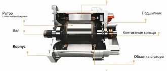
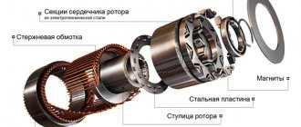
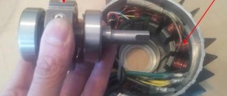
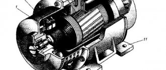
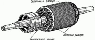
A commutator motor is an electric machine whose rotor position sensor and current switch are one and the same device, called a brush-commutator unit. You can tell us more about the latter. It provides an electrical connection between the circuits in the stationary part of the machine and the rotor circuits. Structurally, it consists of brushes (they mean sliding contacts that are located around the rotating part of the engine) and a commutator (what is located on the movable element of the mechanism).
The general advantages include the fact that the commutator motor is easy to manufacture and operate, has a significant service life and can be easily repaired. Common disadvantages include the fact that they have low mass and high efficiency. In most cases this is only a plus, but not now. Thus, the combination of low mass and speed (which reaches hundreds and thousands of revolutions per minute) leads to the fact that gearboxes are almost always required for normal operation. And when adjusted to low speed, the machine has reduced efficiency, and cooling problems arise. So far, no elegant solution to this problem has been found.
Types of commutator motor
There are two main types, each of them has its own advantages and features. DC commutator motors are very common and varied. Their designs can be divided into the following subtypes:
- The weakest, the operating voltage of which is 3-9 Volts, and which are used in children's toys. They have a two-pole stator in which permanent magnets are installed. The collector unit is constructed of two brushes, which are usually copper plates. Unlike the stator, these motors have a rotor with three poles. It is installed on plain bearings. The power of such mechanisms is measured in several units of watts.
- Medium motors have an operating voltage of 12 or 24 volts. Used in cars, work machines, and ventilation cooling systems. They generate power of several tens of watts. They have a multi-pole rotor, which already operates on rolling bearings. The commutator unit consists of 4 brushes (usually graphite). The stator has four poles, but still consists of permanent magnets.
- There are also engines that can generate power in the hundreds of watts. The only difference from the design described in point 2 is that electromagnets are used for the stator.
But besides such representatives, there are also universal commutator electric motors. Their peculiarity is that they can operate on both direct and alternating current. They are used in power tools, household appliances and railway transport in trains that travel thanks to electric locomotives. Their prevalence is explained by their small size and weight, relatively low price and the ability to easily adjust the number of revolutions. Due to the fact that it is a brushed AC motor, it can also handle intermittent power sources within reasonable limits.
Schematic view of a commutator motor
There is no one generally accepted scheme. What you see is just one of the options. The commutator motor circuit can be built the way you want. There are only requirements for what should be within the working drawing: stator and rotor. A brushed AC motor must also be equipped with a fuse to prevent it from burning out.
How to regulate the number of revolutions?
Changes are possible if a commutator motor speed controller is used. Differences in the amount of electricity supplied can change their quantity by as little as 10 percent, give or take. Whereas the speed controller of a commutator engine allows you to reduce them significantly, and you can make it yourself or buy it. And in any case, you need to check whether it can work in a mechanism of such power and such speed (first theoretically, and then in practice). After all, if the regulator is too weak, then failure will be a breeze for it.
Advantages and disadvantages
The advantages of a commutator motor:
- Low inrush current, which is desirable for household devices.
- Universal motors can be connected directly to the network, without rectification. But this only applies to them. DC motors require rectification.
- It's easier to make a control circuit.
- Speed.
- Greater starting torque.
- The compactness of the circuit even with the use of a gearbox.
- Unstable power value, which is given by the revolutions of the commutator motor when the load changes.
- Relatively low reliability and service life.
- Due to inductance losses and stator magnetization reversal, efficiency may decrease.
Brushless analogue
In terms of mechanical characteristics, the closest is the valve electric motor. The main thing in it is the inverter, and not the brush-collector unit. But the general disadvantage of this design is the lower maximum torque for the same dimensions.
What is the difference between a brushed and brushless motor, their advantages and disadvantages
A large number of people are interested in creating electric models, where one of the main elements is an electric motor. At the same time, the assembly and operation of such devices often causes controversy as to which motors are best to use.
After all, there are brushed and brushless motors to choose from, each of which has its fans and opponents. To try to determine the best option, you need to study the features, how they work, and their strengths and weaknesses. This will greatly help you make your final decision.
Electric motors are part of various automotive equipment, including windshield washers, window lifts, cooling and heating fans, wipers, etc. But they are also widely used in other areas and industries.
Commutator type motor
The concept of commutator motors includes various electric machines, where the current switch and rotary sensor are essentially one device. With its help, a high-quality connection of the circuits in the stationary engine compartment with the working rotor is ensured.
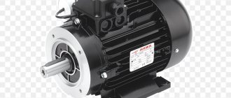
Appearance of a commutator motor
The design includes powerful brushes and the collector itself. It is also interesting that the commutator type of motor has the advantage of ease of maintenance and operation, is easy to repair and lasts a long time. But there is also a drawback, which is manifested in low weight with high efficiency. Initially this may seem like an advantage. The high speed coupled with the low weight forces the use of an additional good gearbox, otherwise it will not be possible to operate the motor normally.
If the machines are adjusted to lower speeds, the efficiency will instantly drop. This, in turn, will negatively affect cooling efficiency.
