The transition to the usual voltage of 220 V was carried out during the years of the Soviet Union and ended in the late 70s and early 80s. Electrical networks of that time were made according to a two-wire circuit, and the wire insulation was monochromatic, mostly white. Subsequently, high-power household appliances appeared that required grounding.
The connection diagram gradually changed to a three-wire one. GOST 7396.1–89 standardized the types of power plugs, bringing them closer to European ones. After the collapse of the USSR, new standards were adopted based on the requirements of the International Electrotechnical Commission. In particular, to increase safety when working in electrical networks and simplify installation, color grading of wires was introduced.
Normative base
The main document describing the requirements for the installation of electrical networks is GOST R 50462–2009, which is based on the IEC 60446:2007 standard. It sets out the rules that the color marking of wires must comply with. They concern manufacturers of cable products, construction and operating organizations whose activities are related to the installation of electrical networks.
Extended installation requirements are contained in the Electrical Installation Regulations. They contain the recommended connection procedure, with reference to GOST-R in paragraphs regarding color gradations.
Why do you need color coding?
Color coding of wires in electrical engineering is a necessity because it makes wiring and reading electrical diagrams much easier. If we consider as an example the connection diagram of a simple light switch, it may seem that marking is not necessary, since everything is simple and clear.
However, if we take as an example the connection diagram of a distribution panel with a large number of differential circuit breakers and protective devices, we will immediately notice the difference.
If it were not for the identification of wires by color, it would be very difficult to figure out which device or cable is faulty and in which circuit they are connected.
In addition, when the wires are painted in a certain color, their installation is greatly simplified, since the likelihood of making a mistake and mixing up the wires is reduced. If, for example, we confuse phase and zero when connecting devices to the electrical panel in our apartment, this can lead to a short circuit, equipment breakdown, or, even worse, electric shock.
Manufacturers paint cable wires in certain colors not in a random order, but according to the rules of electrical installations. They describe exactly what markings can be used on wires under certain conditions. In addition, the 7th edition of the PES (from 2002) prescribes the identification of cables and wires according not only to their color, but also to their symbols.
The need for color separation
A two-wire system implies the presence of a phase and a zero in the network. The plug for such sockets is flat. The equipment is designed in such a way that the correct connection does not matter. It doesn’t matter which contact the phase is applied to, the equipment will figure itself out on its own.
With a three-wire system, an additional grounding conductor is provided. At best, incorrect connection of wires will lead to constant tripping of the circuit breaker, at worst - to equipment damage and fire. The use of color gradation for cores eliminates installation errors and eliminates the need to use special instruments designed to measure the resulting voltage.
Determination methods
Let's look at ways to determine the neutral and grounding conductors, from very simple to more complex.
The circuit has diff current protection
. If the entire object or branch under study is equipped with differential current protection - a differential current device or an RCD, the task is greatly simplified. You need to connect a control device, for example a lamp with conductors, to the phase and to one of the conductors being tested. If the differential protection does not work, then the lamp is connected to the working zero. If an RCD is triggered when a lamp is connected, you connect it to phase and ground. Everything is quite simple and at the same time check the residual current device in practice.
Before performing such a test, you need to make sure that the diff protection is working by pressing the “test” button on the protective device. It should be noted that the method will work provided that the current through the lamp exceeds the rated differential current of the device. That is, when using an incandescent lamp (an energy-saving lamp is not suitable), an RCD with a leakage current of 10-30 mA will trip. The introductory RCD for a 300 mA leak may not work; for a reliable test, you need to take a more powerful device.
Comparison with grounding contacts of sockets
. This method will work if there is a two-pole circuit breaker at the input that opens the working zero and there are grounded sockets in the room. The input machine should be turned off, thereby we will open any connection between zero and ground. If possible, unplug all appliances from electrical outlets.
Next, you should “ring” with a multimeter in resistance measurement mode the grounding contact of one of the sockets with the contacts being tested. When connected to the neutral wire, the multimeter should show a high resistance; with a ground contact at an unknown point with the ground of the socket, the resistance is almost zero.
In this way, you can at the same time check the correctness of the connected sockets: when the input two-pole circuit breaker is turned off, the neutral and ground contacts should not ring. Well, this is provided that the wiring is initially in good working order and installed correctly.
Climb into the shield
. If it is not possible to implement the previous methods, you will have to go into the “stuffing” of the electrical panel. I think there is no point in reminding about safety precautions here: no one has canceled it. In fact, the method is quite simple: you need to find the neutral conductor going into the room and disconnect it from the switchboard terminals. Then ring with the contacts being tested: the one with whom the call will be made is the neutral conductor.
In the case of a shield, difficulties may well arise when even in the shield it is difficult to distinguish zero from grounding. In this case, you will need current clamps
.
You need to turn on the voltage and load in the room, and use clamps to examine unknown conductors in the shield - where there is current, there is a working zero. Please note: the method only works if you know for sure that one of the conductors is zero and the other is ground.
All of the above methods work with both grounding and grounding.
Determine the contacts when connecting an electric stove
. Sometimes it becomes necessary to replace an electric stove socket, but the wiring is from Soviet times or the early 90s, one color. To correctly determine whether an electric stove is zero, a condition is necessary - a two-pole circuit breaker in the input switchboard, which disconnects both phase and zero from the entire apartment.
So, with the power turned on, we determine the phase on the terminals under study for the future socket - we mark this contact and throw it aside, then we don’t need it. Then you need to determine the zero in any socket in the apartment - since the wiring is Soviet, there is no ground there, so the zero will be the terminal on which the indicator screwdriver does not light up.
Now we turn off the power to the entire apartment and use a multimeter to dial the zero of a regular outlet with the two remaining contacts for the electric stove. The contact that rings with the zero of the socket is working, and the one that does not ring is zero (ground). If both contacts ring, you need to look for errors in the electrical wiring. When organizing grounding in Soviet times, it was connected to the “PEN” terminal without any switching devices.
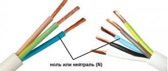
Three-wire system
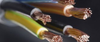
Let's look at a cross-section of a three-core wire, which is used for laying household electrical networks.
The color of the wires indicates where the phase, neutral and ground are located. Additionally, the figure shows typical letter symbols used in electrical circuits. By picking up such a drawing, you can visually determine the correctness of the connection.
Let's take a look at GOST and see how well the color coding of wires shown in the figure meets the requirements. Clause 5.1 of the general provisions describes the twelve colors that must be used for marking.
Nine colors are allocated to indicate phase wires, one for neutral and two for grounding. The standard provides for a grounding wire in a combined yellow-green design. Longitudinal and transverse application of stripes is allowed, and the predominant color should not occupy more than 70% of the braiding area. The separate use of yellow or green in a protective coating is expressly prohibited by clause 5.2.1.
The specified circuit is used for single-phase connection, suitable for most electrical appliances. It is almost impossible to get confused in it, with a correctly marked wire.
Features of phase wire coloring
Coloring of phase wires
Phase wires pose the greatest danger to those who work with electrical wiring. If you accidentally touch a bare phase wire, you can receive an electric shock, sometimes fatal. The brightest colors are used to indicate the phase conductor. By this coloring you can easily determine which conductor is the most dangerous, so working in such conditions is much easier.
Typically, phase conductors are black or red, but there are times when they are left brown, orange, lilac, pink, purple, white, gray, etc. If you take these colors as a basis, then it is much easier to work with such electrical wiring, especially since the neutral wire and ground wire have a fixed color.
If you look at the wiring diagram, the phase conductors are designated by the letter “L”. If there are several phase conductors, then they are designated in order - L1, L2, L3, etc. If the network is 3-phase, then the phases are designated by the letters “A”, “B” and “C”.
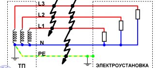
Five-wire system
For a three-phase connection, five-core wires are used. Accordingly, three wires are allocated for phases, one for neutral or zero and one for protective, grounding. Color marking, as in any alternating current network, is similar, in accordance with GOST requirements.
In this case, the correct connection of the phase conductors will be an important point. As can be seen in the figure, the protective wire is made in a yellow-green braid, and the neutral wire is in blue. Allowed shades are used for the phases.
Using five-core wires, you can connect a 380 V network with correct wiring.
3rd way to distinguish the grounding conductor from the neutral conductor
This method is applicable when a two-pole circuit breaker is installed at the input (that is, the machine simultaneously disconnects the phase and neutral conductors):
- ⚡turn off all devices and the input machine
- ⚡Using a multimeter in the “dialing” mode, connect the intended grounding wire and the metal casings of the nearest equipment that must be grounded - batteries, bathroom, etc.
- ⚡that core on which the tester will show a value close to zero or emit a sound signal will be the ground. Where the resistance is close to infinity is the working zero.
Combined wires
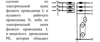
In order to reduce the cost of production and simplify connections, two- or four-core wires are also used, in which the protective conductor is combined with the neutral conductor. In the documentation they are designated by the abbreviation PEN. As you guessed, it consists of the letter designations of the neutral (N) and ground (PE) wires.
GOST provides special color markings for them. Along their length, they are painted in the colors of the grounding conductor, that is, yellow-green. The ends must be painted blue, which additionally marks all joints.
Since the places where the connection is made cannot be determined in advance, at these points the PEN wires are isolated using insulating tape or blue cambrics.
What color is the neutral wire?
Zero or neutral is blue or light blue, sometimes blue with a white stripe. Other colors are not used in electrical engineering to indicate zero. It will be like this in any cable: three-core, five-core or with a large number of conductors.
What color is the neutral wire? Blue or cyan
“Zero” is usually drawn in blue on diagrams and signed with the Latin letter N. Experts call it a working zero, since, unlike grounding, it participates in the formation of the power supply circuit. When reading a diagram, it is often defined as "minus", while the phase is considered "plus".
Non-standard wires and markings
When purchasing a new wire, you will, of course, pay attention to the color marking of the cores and choose the option where it is applied correctly. What to do if the wiring has already been completed, but the colors of the wires do not meet the requirements of GOST? The output in this case is the same as with PEN wires. You will have to perform manual marking after you have decided on the role played by the conductors suitable for the equipment. A simple option would be to use colored electrical tape in appropriate shades. At a minimum, it is worth identifying the protective and neutral wires.
During professional installation, it is possible to use special cambrics, which are hollow pieces of insulating material. They are divided into regular and heat-shrinkable. The latter do not require selection by diameter, but do not have the possibility of reuse.
There are also specially made markers with international alphanumeric designations. They are used on input and distribution boards, for example, in apartment buildings or administrative buildings.
Digital tags, together with the color of the wire, allow you to determine which consumer is supplied with power.
How to mark a wire with two cores
If all the wires in the cable have the same insulation, and the electrical appliance is already connected to the network, the craftsmen use indicator screwdrivers. The latter glow when the metal part touches the phase wire. To mark a two-core cable, in addition to such a screwdriver, you will need thermal casings or multi-colored electrical tape. Colors will be marked only at the joints - it is not necessary to wrap the core with colored tubes or electrical tape along its entire length.
Probe screwdriver-indicator
Phase wires can be marked with any colors except blue, yellow and green. If a two-core cable is connected to a single-phase network, it is customary to secretly mark the phase wire in red.
Additional requirements
Since lines, like wiring, can be made using various cable products, there are a number of rules for their mutual connection. The connection of a three-wire cable to a five-wire cable must be carried out in compliance with the color markings from master to slave. Accordingly, the grounding and neutral colors must match.
Phase connection, in this case, is performed using a unifying bus. On the one hand, three cores are connected to it, on the other hand - one, which will be the phase in the new branch.
When installing household electrical networks, according to safety requirements, it is prohibited to use wiring with aluminum or multi-wire conductors. Only solid copper cable should be used.
Practice
Having started directly to electrical installation work or repairs in electrical wiring, you may encounter non-compliance with the color regulations, which are established by regulatory documents. As practice shows, this case is not the rule, but the exception.
- you can buy a three-core cable of type BBG 3x1.5, which has cores with white, red and brown colors;
- cable products are often found with white wires with a colored stripe of black, gray or blue along the entire length;
- In the electrical wiring that was done before, in general, you can find a two or three-core white wire.
Here are some practical tips that will come in handy:
- When making repairs in existing networks, it is necessary to use electrical safety devices, such as a voltage indicator or an indicator screwdriver. With their help you can always determine the color of the phase wire.
- If the correct color marking of cable products is not available, purchase cambric or insulating tape of the required color. The main thing is to designate the color of the ground wire as yellow-green, the working zero as blue, and for phase L in the electrics you can choose any other color.
- To install new wiring, use a cable of the same brand so that there is no confusion with the color of the wires in the electrical system.
Three-wire DC system
In DC systems, a three-wire system is also used, but the purpose of the wires is different. The division is made into positive, negative and protective. According to GOST, the following color markings are used in such networks:
- Plus - brown;
- Minus - gray;
- Zero - blue.
Since it is irrational to produce separate wires for DC systems, the specified color gradation is used mainly for painting conductive busbars.
Features of core colors
To avoid errors, the PUE requirements describe the colors of all main electrical wires. If the commissioning work was carried out by an experienced electrician who follows the rules of the Electrical Installation Code and the relevant GOSTs, during independent repairs you will not need either an indicator screwdriver or other devices that determine the purpose of a particular core.
Color marking in electrical equipment according to GOST
Colorless flat three-core wires when installing PPV: how to determine?
It is possible to determine the phase and neutral conductors not by markings. This is done using an indicator screwdriver or a multimeter.
Finding a phase core using an indicator is quite simple. You need to touch the controlled section of the circuit with the conductive tip of a screwdriver.
You need to touch the contact pad with your finger. If the indicator lights up, then the tested core is a phase. Otherwise it is zero.
Move the tester to the position of checking alternating voltage with a limit above 220 V. In turn, you need to measure between a phase and another conductor. The larger number is the value between the phase and the working zero, the smaller number is between the phase and ground conductor. This method is rarely used; it is better to find the ground by marking and connecting to the ground contacts.
You can also find the phase cable using a light bulb by screwing it into the socket. Find 2 pieces of electrical wires with bare ends - one is grounded. Touch the wire with the other end. If the lamp lights up, then this is the working phase.
4th way to determine grounding and grounding
- ⚡ turn off all devices in the apartment, not only with the switch, but also from the sockets
- ⚡turn off the input two-pole circuit breaker
- ⚡at the output from the machine between the neutral and phase wires, place a jumper - a shunt
- ⚡Using a tester in diode testing mode, take measurements on the conductors in the socket box
- ⚡phase and zero cores must give a complete zero between themselves. The tester will beep.
- ⚡the remaining core is the grounding one
This method is the least preferable and carries great risks for an inexperienced user of electricity. Therefore, use it last if you have the necessary skills and knowledge.
Source: domikelectrica.ru