The owner of an apartment or private house who decides to carry out any procedure related to electricity, be it installing a socket or switch, hanging a chandelier or wall lamp, is invariably faced with the need to determine where the phase and neutral wires are located at the place of work, as well as the grounding cable. This is necessary in order to correctly connect the mounted element, as well as to avoid accidental electric shock. If you have some experience working with electricity, then this question will not confuse you, but for a beginner it can be a serious problem. In this article we will understand what phase and zero are in electrics, and we will tell you how to find these cables in a circuit, distinguishing them from each other.
Let's understand the basic terms
Everyone encounters such terms as “phase” and “zero” in their lives every day. All of them are closely related, because they relate to electricity, and this is something without which the life of a modern person is unthinkable. To understand their nature and more or less learn to understand electrics, you should first understand a number of fundamental concepts.
Let's start with the basics
Electric charge is a characteristic that determines the ability of various bodies to be a source of an electromagnetic field. The carrier of such waves is the electron. By creating an electromagnetic field, you can “force” electrons to move. This is how current is generated.
Current is a clearly directed movement of electrons along a metal conductor under the influence of an existing field.
Types of current
The current can be constant or alternating. A current that does not change in value over a period of time is a current of constant value. A current, the magnitude of which, like the direction, changes over time, is called variable.
Constant current sources - batteries, batteries, and so on. Alternating current is “suitable” for household and industrial sockets in homes and businesses. The main reason for this lies in the fact that this type of current is much easier to obtain physically, convert to different voltage levels, and transmit through electrical wires over vast distances without significant losses.
Basic characteristic of alternating current
Alternating current is usually a sine wave, or sinusoidal current. It can be characterized as follows: first it increases in one direction, reaching its maximum value (amplitude), then it begins to decline. At some point in time it becomes equal to “0” and then begins to increase again, but in a completely opposite direction.
"Phase", "zero" and "ground"
The simplest case of an electrical circuit through which a sinusoidal current moves is a single-phase circuit. It consists, as a rule, of three electrical cables: along one of them, electricity approaches devices and lighting elements, and through the second, it “leaves” in the opposite direction - away from the consumer. The third conductor is the “ground”.
The wire through which electricity reaches electrical consumers is called a phase, and the cable used for return movement is called zero.
The most efficient network for transmitting electric current is a three-phase system. It includes three phase cables and one return cable - zero. This type of current is suitable for all residential areas. Immediately before entering the apartment, the electric current is divided into phases. Each phase is “assigned” one zero. The advantages of such a system are that with a balanced load, the current through zero (and in such a system there is only one - common) is zero.
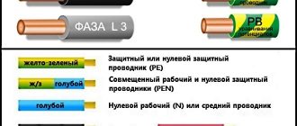
To avoid mixing up the wires and preventing a short circuit, each wire is painted a different color. However, the color of the wire does not guarantee its purpose!
The “earth” does not carry any electrical load, but serves as a kind of safety element. At that moment, when something in the power supply system gets out of control, the ground wire will prevent electric shock - it will “drain” all excess voltage, that is, it will be discharged to the ground.
Phase and zero: their meaning in the power supply network
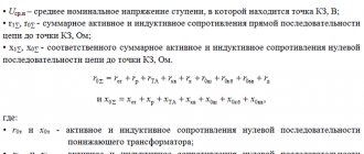
Electricity is supplied to consumer sockets from substations, which reduce the incoming voltage to 380 V. The secondary winding of such a transformer has a “star” connection - its three contacts are connected to each other at the “0” point, the remaining three outputs go to the “A” / “B” terminals "/"WITH".
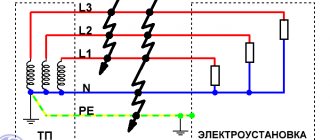
The wires connected at point “0” are connected to “ground”. At the same point, the conductor is divided into “zero” (indicated in blue) and a protective “PE” cable (yellow-green line). This model of wiring is used in all houses currently being built. It is called the “TN-S” system. According to this diagram, three phase cables and two indicated zeros are suitable for the distribution equipment of the house.
In houses, enterprises and buildings of old construction there is often no “PE” conductor and therefore the circuit turns out not to be five-wire, but four (it is designated as “TN-C”).
All electrical wires from the substations are connected to the panel, forming a three-phase system. Then there is a division into separate entrances. Each of the entrance apartments is supplied with only one phase voltage - 220 V (wires “O” / “A”) and a protective “PE” cable.
With this scheme, the entire load on the power supply system is distributed evenly, since on each floor of the house specific panels are wired and connected to a specific 220 V power line.
The supply voltage circuit is a “star”, which exactly repeats all the vector characteristics of the supply substation. When there are no consumers in the sockets, no current flows in this circuit.
This connection scheme has been worked out for years. It confirmed its right to use by being recognized as the optimal of all existing ones. However, in it, as in any device, mechanism or device, all kinds of breakdowns and malfunctions may periodically appear. As a rule, they are associated with poor quality electrical connections or complete cable breaks in some places in the circuit.
Cases of breaks in the conductive circuit
If a zero/phase break occurs inside a single apartment, then the connected device, as a result, will not function.
A similar situation will arise if the contacts of the wires of any of the phases supplying the access panel are broken. In this case, all apartments receiving power from this power line will not receive electricity. At the same time, in the two remaining circuits the devices will function as before.
From these diagrams it is clear that a complete power outage in apartments is associated with a break in one of the wires. This does not lead to damage or failure of the devices. The most serious situation is a break between the grounding loop and the central connection point of all consumers.
In this case, the entire electric current stops flowing along the working zero to the “ground” (AO, VO, CO) and begins to move along the path AB/BC/CA to which 380 V is supplied.
A “phase imbalance” occurs. In phases with a higher load, the voltage will be less, and with a lower load, more and can reach significant values, close to 380 V. This will cause damage to the insulating materials, heating and failure of the equipment. A system of protection against overloads and high voltages mounted in apartment panels allows you to prevent such cases and protect expensive equipment.
Phase, zero, ground - what is it?
Having briefly examined the basics of alternating current, we will finally define the concepts of phase, zero, and ground. As a rule, there are no special problems in understanding the phase. We all know that it is energized and should not be touched. All solidly grounded systems have a grounded neutral point in the distribution transformer. By touching the phase, we close the circuit through the ground and a dangerous current passes through the body.
Now let's deal with zero. As mentioned above, zero is the point of connection of three phases with loads. Also, zero is the point of connection of the ends of the secondary windings in the transformer. And we all, as a rule, understand zero as the fourth wire that connects two zero points. Is it correct? Correct, but for complete understanding it is necessary to separate all these areas.
Let's consider zero as the common connection point of phase loads. Why zero? Because if the load is symmetrical, then the potential at this point is 0 Volt. And in fact, by calculating the potential difference between three phases with voltage values of +312, -156, -156 Volts, we get 0 Volts.
In real life, all three phases cannot be loaded equally. In this regard, potential already appears at the zero point. And if the load unevenness is significant, this potential can be very large, and the voltage variation among consumers can be from low to very high. And to prevent this from happening, the zero points are connected with a wire. And since the neutral of the transformer is solidly grounded, this fourth wire is nothing more than a PEN conductor. A current always flows through it, which is equal to the geometric sum of all phase currents.
At this stage, it is appropriate to warn everyone, do not listen to the harmful advice of many incompetent electricians and never touch the neutral (PEN) conductor. He's always energized. Most often it is low, but sometimes it is dangerously high (when the total zero is broken). And the fact that the PEN conductor is grounded does not play any role. Zero is charged with current, since the PEN conductor has its own resistance. And the longer it is, the greater the resistance at a point remote from the transformer. And if there is resistance, then there will be a potential difference with the ground, and if you touch the neutral wire, current will pass through you. And here another nonsense does not work that the current flows along the path of least resistance. The current in a closed circuit is distributed everywhere, only its strength is inversely proportional to the resistance.
Let's finish the topic with earth. If we consider the common TN system, then the colloquial name “ground” should be understood as protective grounding. Protective grounding in electrical installations with voltages up to 1 kV is a deliberate connection of open conductive parts with a solidly grounded neutral of a generator or transformer in three-phase current networks, with a solidly grounded output of a single-phase current source, with a grounded source point in direct current networks, performed for electrical safety purposes. That is, zero and ground are connected at some point before separation. Therefore, both zero and ground do not need to be touched without first checking.
Features of the neutral wire
The neutral wire prevents undesirable situations during emergency operation. Without it, in the event of a phase short circuit of two phases, the voltage in the third phase will instantly increase by √3 times. This will have a detrimental effect on the equipment that powers this source. If there is a zero in this situation, the voltage will not change.
If one of the phases in a three-phase three-wire system (without zero) breaks, the voltage on the two remaining phases will decrease. They will be connected in series, and with this type of connection the voltage is distributed among consumers depending on their resistance. If one of the phases in a three-phase four-wire system breaks, the voltage in the two remaining phases will not change its value.
Fuses are not installed in the neutral wire due to its great importance, because its breakage is undesirable
Since most of the time electrical installations operate, the current in this wire is either zero or insignificant, there is no point in making it the same cross-section as the phase wire cross-section. Most often, for reasons of economy, it has a smaller cross-section of the conductor than the cross-section of the conductors of the phases in one electrical installation. If the protective wire is not combined with the neutral wire, its cross-section is half that of the phase wire.
Alternating voltage - three phases and zero
It’s worth starting with the basics - with alternating voltage and current, its nature and the principle of transmission to end consumers. The topic of alternating current deserves separate consideration, but to understand phase, zero and ground at the household level, we will highlight the main points.
The power plant's powerful generators produce voltages of tens of kilovolts. Then, through step-up and step-down transformers, electricity comes to homes with the usual parameters of 220 Volts 50 Hertz. The last intermediate element between the power plant and the house is a step-down distribution transformer. We won’t go into the specifics of its work now. But for understanding, let’s replace it, all intermediate transformations and the generator at the power plant with a conventional three-phase 220 Volt generator.
A three-phase generator simply consists of a rotor (rotating magnet) and three stator windings, offset from each other by 120° (three phases - hence the name phase, indicating the terminal of the beginning of the winding). The beginnings and ends of the windings of a three-phase generator are usually designated by the letters A, B, C and X, Y, Z. The first letters of the Latin alphabet indicate the beginnings of the windings, and the last letters indicate the ends. The ends of the windings are connected in a star into one node, called the neutral or zero point. The same principle applies to a step-down distribution transformer - the ends of the windings are connected at the zero point, and the beginnings of the windings are three phases with a linear voltage of 380 Volts.
The generator rotor, rotating, creates an electromotive force, which, provided that the circuit is closed, causes free electrons in the wires to move directionally from a zone with a high potential (an excess of electrons) to a zone with a lower potential (a lack of electrons). Let's conditionally stop time and consider what happens to the voltages in each phase. We know that the voltage in the socket between phase and zero is 220 Volts. This is the effective voltage value, and after converting to amplitude, we get 312 Volts. Let's assume that this is the voltage at terminal A of the generator (or transformer). To determine the voltage on the two remaining terminals, we also conventionally assume that the consumption in the three phases is symmetrical. Then the neutral wire is actually not needed, so we disconnect it from the generator (transformer) - in life this situation is called a break (burnout) of the common zero. But we still have zero. It is important to understand that zero is not just the fourth wire from the transformer. Zero is primarily the common connection point of three phase loads. And current ideally does not flow from phase to zero of the transformer and back. Current flows between three phases if the loads are symmetrical. And only when the loads are asymmetrical (and in real life this is always the case) only part of the current through the fourth wire returns to the transformer.
Assuming that our load is symmetrical, and zero is the connection point of the transformer windings after the loads, we can now find the voltages at the remaining phase terminals and understand the essence of alternating voltage. Since current flows, more precisely, the movement of free electrons occurs between three phases, then if the voltage at terminal A is 312 Volts (take it with a “+” sign, the voltage at the terminal is the potential difference between the beginning and end of the winding (zero point)), then the remaining two terminals B and C should be (it is) -156 Volts. That is, electrons in the circuit begin to move from an area with a potential of +312 Volts to areas with a potential of -156 Volts. If you remember, we stopped time and looked at a specific moment. Let's turn off the time stop. Now the rotor is spinning and the voltage values at the terminals change in a sinusoidal manner. The electrons still move between the phases, but periodically change directions. Concluding a brief excursion into alternating current, I would like to note that when talking about the movement of electrons, we need to understand not the passage of huge distances at the speed of light, but rather millimeters (centimeters). Electrons are slow and do not travel at the speed of light in wires. Propagation at the speed of light occurs only in the electric field, which interacts with all free electrons on any section of the wire.
It will be interesting➡ How to connect a switch with two keys? Detailed connection diagram
Classification of power line neutrals
The purpose of power lines is very diverse. There is also a variety of equipment to protect them from leaks and short circuits. In this regard, neutrals are classified into three types:
- solidly grounded;
- isolated;
- effectively grounded.
If the power line with voltage from 0.38 kV to 35 kV is short and the number of connected consumers is large, then a solidly grounded neutral is used. Consumers of a three-phase load receive power thanks to three phases and zero, and consumers of a single-phase load receive power from one of the phases and zero.
With an average length of power lines with voltages from 2 kV to 35 kV and a small number of consumers connected to this line, insulated neutrals are used. They are widely used for connecting transformer substations in populated areas, as well as powerful electrical equipment in industry.
In networks with a voltage of 110 kV and higher, with a large length of power lines, an effectively grounded neutral is used.
Phase and zero in electrics
Electricity appears as a result of the ordered movement of charged particles in wires - electrons. These electrons are born in huge power plants - such as, for example, the Volgograd State District Power Plant (hydroelectric power plant), Novovoronezh Nuclear Power Plant (nuclear power plant) and many others in our country. Then, through very thick wires, this energy is transmitted to intermediate substations (as a rule, these are located on the periphery of cities), and from them to the local transformer substation (complete transformer substation), which is located in almost every yard.
Power line
Voltage levels in such networks vary from 750,000 volts to 380 volts at the final transformer substation. And it is the latter who make it so that 220V appears in the socket of an ordinary house. It would seem that everything is simple, but! There are two wires in the socket. And from physics lessons, everyone knows that in electrics there is a “phase” and a “zero”. These two words give us light, heat, water, gas and much more that we use every day. Now, in order.
KTP
Reaction of electrical appliances to zero loss
If the common neutral wire in a multi-story building breaks, consumers will feel it as a result of a voltage surge in their electrical appliances.
The main factors that can lead to loss of power to the common zero:
- emergency situation at the substation;
- outdated wiring;
- The wiring installation was not done very well.
The phase to which more consumers of the apartment building are connected will be overloaded. The tension in it will decrease. In the phase to which the least number of consumers are connected, the voltage will increase sharply.
This will have a negative impact on the devices - a decrease in voltage will cause them to operate ineffectively, and an increase in voltage may lead to the failure of those that are currently connected. To protect yourself from such a situation, you need to install an individual surge suppressor in the panel that supplies a separate apartment. As soon as the voltage begins to exceed permissible values, the limiter will quickly turn off the power.
If a zero break occurs directly in the apartment, the electricity will be lost completely, but at the same time the phase will not be turned off. The danger is that it can go right to the neutral wire. And if any electrical device was previously grounded to it, the body of this electrical device will be energized, or, more simply put, it will begin to “beat with current.”
The main factors that contribute to the loss of zero directly in the apartment can be called:
- unreliable connection of contacts;
- incorrectly selected conductor cross-section;
- outdated wiring.
These factors lead to excessive heating of the conductor. Due to the increased temperature, the place where the contacts are connected oxidizes, and the wire strands overheat. And this, in turn, can lead to a fire.
Confuse phase and zero
In the early days of electrification, connecting a light fixture was a simple process. Very often the entire structure was a socket with a built-in switch, and sometimes also with a socket.
Nowadays, a chandelier can be a complex structure, the incorrect connection of which can lead to protection activation or incorrect operation of the lamps. The situation is complicated by the fact that the wires in the cable are different - neutral, phase and ground.
connecting a five-arm chandelier
If the grounding is connected to the lamp body, then the issue with the remaining conductors is more complicated, so when performing this work it is important to know what will happen if you mix up phase and zero when connecting the chandelier
What is the danger of damaging the neutral wire?
Overheating of the neutral wires due to poor contact.
Zero is damaged due to mechanical stress, short circuits, poor-quality connections or as a result of old wiring. Neutral break:
- PEN conductor in the power cable - there is only one ground loop left, which is not visually noticeable;
- combustion of a conductor in the switchboard - phase conductors become distorted, the voltage increases to 380 V;
- there is a break in the apartment panel - the second phase remains in the sockets, household appliances are not powered from them.
Phase and neutral in a modern socket
Modern devices have three wires. The phase comes in any color. In addition to phase and neutral, there is one more wire (protective neutral). The color of this conductor is green or yellow.
Voltage is supplied through the phase. Zero is used for protective zeroing. The third wire is needed as additional protection - to draw in excess current during a short circuit. The current is redirected to the ground or in the opposite direction - to the source of electricity.
Note! It makes no practical difference whether phase and zero are located on the right or left. However, most often the phase is located on the left and the zero is on the right.
What is grounding and neutral wire
The neutral conductor also balances the potentials in several phases. According to the PUE, the task of the neutral is to provide current to consumers. It must be connected to a solidly grounded neutral point of the transformer. In private houses and apartments where single-phase electrical networks are used, there must be two cables for the equipment to operate: phase and neutral. “Zero” is connected to “ground”, and its potential must be equal to 0. It is connected to “ground” using a ground loop.
Accordingly, there should be no voltage. If communication with it is disrupted during operation of the equipment, it will be under the same voltage as in the phase, respectively - 220. On modern diagrams it is designated by the letter N, and in Soviet documents, already outdated, the number 0 was used. According to the PUE, the cable must cover with blue insulation.
The grounding conductor, according to the PUE, is needed for safety purposes. Under normal conditions, there is no voltage on it, and it works as a conductor only if the insulation of the conducting phase or neutral is damaged. Accordingly, grounding is necessary so that in the event of a breakdown no additional problems arise. For example, when your refrigerator’s protection is broken, and the refrigerator itself is not grounded, touching it will be equivalent to touching the 220 V phase. But if the refrigerator is grounded, it will not give an electric shock, since the potential will go into the ground.
The protective conductor is designated by the letters “PE”. According to the rule, its insulation must be painted in yellow and green stripes. If the diagram has the designation “PEN”, it means that the neutral and protective wires are combined into one. Such a cable should be painted blue with yellow and green stripes at the ends.
To equalize different voltages, all ends of the phase windings are connected into a node, which is called a neutral point, for which a neutral wire is used when connected in a “star”. The star circuit with neutral is used in practice, because in it, at any load, there is no phase imbalance in voltage, i.e. all phase voltages are equal.
If you take into account all of the above, then you probably understand the critical importance of a neutral cable that equalizes voltage in several phases, because its absence threatens with serious problems - from damage and loss of equipment to fires and even the risk of fatal electric shock to a person.
Home electrical wiring: finding zero and phase
You can determine at home where which wire is located in different ways. We will analyze only the most common ones that are accessible to almost anyone: using an ordinary light bulb, an indicator screwdriver and a tester (multimeter).
About the color marking of phase, neutral and ground wires in the video:
Checking with an electric lamp
Before you begin such a test, you need to assemble a testing device using a light bulb. To do this, it should be screwed into a cartridge of suitable diameter, and then secured to the wire terminal, removing the insulation from their ends with a stripper or an ordinary knife. Then the lamp conductors must be applied one at a time to the cores being tested. When the lamp lights up, it will mean that you have found a phase wire. If you check a cable with two cores, it is already clear that the second one will be zero.
Checking with an indicator screwdriver
A good assistant in work related to electrical installation is an indicator screwdriver. The operation of this inexpensive instrument is based on the principle of capacitive current flowing through the indicator body. It consists of the following main elements:
- A metal tip shaped like a flathead screwdriver that is applied to wires for testing.
- A neon light bulb that lights up when current passes through it, thus signaling phase potential.
- A resistor to limit the amount of electrical current that protects the device from combustion under the influence of a powerful flow of electrons.
- A contact pad that allows you to create a circuit when you touch it.
Professional electricians use more expensive LED indicators with two built-in batteries in their work, but a simple device made in China is quite accessible to anyone and should be available to every home owner.
If you check the presence of voltage on the wire using this device in daylight, you will have to look more closely during the work, since the glow of the signal lamp will be difficult to see.
When the screwdriver tip touches the phase contact, the indicator lights up. In this case, it should not light up either at the protective zero or at the grounding, otherwise we can conclude that there are problems in the connection diagram.
When using this indicator, be careful not to accidentally touch a live wire with your hand.
About determining the phase clearly in the video:
Checking with a multimeter
To determine the phase using a home tester, you need to put the device in voltmeter mode and measure the voltage between the contacts in pairs. Between the phase and any other wire, this indicator should be 220 V, and applying probes to the ground and protective zero should show the absence of voltage.
What is grounding?
Grounding or protective conductor in accordance with clause 1.7.34 of the PUE is intended exclusively for electrical safety purposes. Under normal conditions, it is not energized and acts as a conductor only in cases of failure of the insulation of the phase or neutral conductor. At the same time, at the electrical installation itself, it reduces the potential to bladeless.
Why is grounding needed?
- In simple terms, grounding is necessary only in case of breakdown. For example, you have a breakdown in the insulation of your washing machine. If it is not grounded, then touching it is equivalent to touching a phase wire. If it is grounded, then nothing will happen, since the excess potential will go into the ground through grounding.
- Grounding can be done using different schemes depending on your capabilities and the power supply circuit. We will consider this issue below.
- The protective conductor in the diagrams is usually designated by the symbols “PE”. The conductor itself should be made of yellow-green wire.
- On some diagrams you may see the designation “PEN”. This means the combination of the neutral and protective wires. We'll talk about it a little lower. The color of such a wire, according to clause 1.1.29 of the PUE, should be blue with yellow-green stripes at the ends.
Connection diagrams for neutral wire and grounding
Now you know how to distinguish the neutral wire from the ground and understand that both are connections to the ground. Now you can consider possible schemes for connecting the neutral wire and grounding. All of them are clearly specified in clause 1.7.3 of the PUE. We will consider only circuits with a solidly grounded neutral that are used in our electrical networks.
TT system
- First of all, let's consider a CT system in which the neutral wire is connected to the grounding of the transformer, and the grounding to an independent source. This method is used very rarely, and the cost of installing such a system is the highest.
- Much more commonly used are TN type systems that use PEN conductors. That is, along the entire length or in certain sections, the neutral and protective conductors are laid with one wire, or are connected to one grounding point.
TN-S system
- The most optimal in this case in matters of electrical safety is the TN-S system. In it, the neutral and protective conductors are connected to a single grounding point, but along their entire length they are made of separate conductors.
TN-C system
- Much more often you can find the TN-C system, which is quite easy to implement with your own hands. In it, the neutral wire and grounding are made of one wire along the entire length. But this is the least safe option in terms of electrical safety.
TN-CS system
- And the last possible option is the TN-CS system. As the name implies, it combines the two previous systems. That is, in one section the neutral and grounding are laid together, and in the second section they are separated.
Rules for connecting the neutral wire and grounding
Knowing the possible connection diagrams for grounding and the neutral wire, we can talk about the rules and requirements for their connection. After all, although they are not significant, they differ. In addition, we hope that we will explain the frequently asked question of why the neutral wire should be grounded.
- First of all, let's talk about the TT system. According to clause 1.7.59 of the PUE, this system can only be used in exceptional cases when none of the TN systems can provide the required level of protection.
Note! When using the TT system, the use of RCDs is mandatory. Moreover, the PUE standards impose separate requirements on them in terms of operating current.
- But for the TN system everything is not so simple. According to clause 1.7.61 of the PUE, at the entrance to the building or electrical installation, they must be re-grounded. Let's figure out why this is necessary.
- In the TN system, as we already know, the neutral and protective conductors are mounted with one wire. If this joint wire breaks, it turns out that the neutral and protective wires form a single whole. After all, they are not connected to the ground.
- If we do not have a connection to the ground, then, as we already know, when you turn on any electrical appliance or even a light bulb, the neutral wire ends up under phase voltage.
- But for a TN system, the neutral and phase wires are partially or completely combined. That is, the grounding wire is also under phase voltage. And our phase wire is connected to the body of our washing machine, hair dryer, refrigerator and other electrical equipment. It turns out that phase voltage will appear on their body. And if you touch them, you will receive an electric shock.
Phase and zero: concepts and differences
There is such a thing as tension. This word means the degree of electric field strength at a given point or circuit. Otherwise it is called potential. In very simple words, this is a kind of piston that gives an impetus to electrons so that they pass through the wires and light a light bulb in a chandelier.
In the common circuit (phase zero), the one that comes to the chandelier or socket, there are two wires. One of them is a phase. It is this wire that is live. A phase in electrical engineering is comparable to a positive in a car - it is the main power supply for the network.
Phase, neutral, ground in the socket
Zero is a wire that is not energized (this is exactly what distinguishes zero from phase). It is not overloaded during the power take-off process, but, nevertheless, electric current also flows through it, only in the direction opposite to the phase one. In the absence of voltage, it is safe in terms of electric shock to a person.
Re-grounding the neutral wire
Re-grounding of the neutral conductor is protection installed at the intervals specified by the rules of the Electrical Installation Code along the entire length of the neutral. The task of re-grounding includes reducing the voltage in the neutral wire and electrical appliances that have been grounded relative to the ground. This property is useful as protection against a break in the neutral wire and in the event of a breakdown of electrical voltage on the housing of electrical devices.
When creating protection in the electrical network, try to select the neutral and protective conductors in such a way that in the event of a short circuit to the metal body of the equipment, a short circuit in the network or melting of the fuses occurs. Usually, when a circuit breaker is installed, this factor causes it to trip.
Important! If a short circuit occurs in a neutralized electrical circuit, the resulting voltage must be three times higher than the rated current.
The neutral must be continuous from each electrical installation housing to the neutral conductors of the electricity sources.
A few words about the structure of the home electrical network
In the vast majority of cases, in apartments it is practiced to install a single-phase power supply network of 220 V/50 Hz. A three-phase powerful line is supplied to a multi-storey building, but then in the distribution boards switching is carried out to consumers (apartment) using one phase and a neutral wire. They try to perform the distribution as evenly as possible so that the load on each phase is approximately the same, without severe distortions.
Expert opinion: Afanasyev E.V.
Chief editor of the Stroyday.ru project. Engineer.
In modern houses, it is practiced to lay protective grounding circuits - most modern powerful household appliances require such a connection to ensure safe operation. Thus, three wires are suitable for sockets or, for example, for many lighting fixtures - phase L (from English Lead), zero N (NULL) and protective ground PE (Protective Earth).
Older buildings often do not have a grounding loop. This means that internal wiring is limited to only two wires - zero and phase. It’s simpler, but the level of safety in operating electrical appliances is not up to par. Therefore, when carrying out major repairs of the housing stock, measures to improve internal electrical networks are often included - a PE circuit is added.
Modern single-phase home electrical wiring should ideally be organized with three wires - phase, working zero and protective grounding
In private houses, input of a three-phase line can also be practiced. And even some points of consumption are often organized with a three-phase voltage of 380 volts. For example, this could be a heating boiler or powerful technological machine equipment in a home workshop. But the internal “household” network is still made single-phase - just three phases are evenly distributed along different lines to prevent distortion. And in any ordinary outlet we will still see the same three wires - phase, neutral and ground.
By the way, in this case, grounding is clearly mentioned. And this is for the reason that the owner of a private house is not bound by anything and is simply obliged to organize it if such a contour did not exist, say, when purchasing a previously constructed building.
Grounding in a private house - how can you do it yourself?
Having a protective grounding circuit in your residential property means significantly increasing the level of safety in the operation of electrical appliances. And by and large - and in general the degree of safety of living in a house for the whole family. If it does not exist yet, then, without delaying for long, you need to organize grounding in the house with your own hands . To help, there is an article on our portal, to which the recommended link leads.
How phase wires are painted
When working with wiring, phase wires pose the greatest danger. Touching the phase, under certain circumstances, can become lethal, which is probably why bright colors were chosen for them. In general, the colors of electrical wires allow you to quickly determine which of a bunch of wires are the most dangerous and work with them very carefully.
Coloring of phase wires
Most often, phase conductors are red or black, but other colors are also found: brown, lilac, orange, pink, purple, white, gray. Phases can be painted in all these colors. It will be easier to deal with them if you exclude the neutral wire and ground.
In the diagrams, phase wires are designated by the Latin (English) letter L. If there are several phases, a numerical designation is added to the letter: L1, L2, L3 for a three-phase 380 V network. In another version, the first phase is designated by the letter A, the second by B, and the third by C .
Ground wire color
By modern standards, the ground conductor is yellow-green. It usually looks like yellow insulation with one or two longitudinal bright green stripes. But there are also transverse yellow-green stripes in color.
Grounding may be this color
In some cases, the cable may only have yellow or bright green conductors. In this case, the “earth” has exactly this color. It is displayed in the same colors on diagrams - most often bright green, but it can also be yellow. Signed on circuit diagrams or on ground equipment in Latin (English) letters PE. The contacts to which the “ground” wire must be connected are also marked.
Sometimes professionals call the grounding wire “neutral protective”, but do not be confused. This is an earthen one, and it is protective because it reduces the risk of electric shock.
What color is the neutral wire?
Zero or neutral is blue or light blue, sometimes blue with a white stripe. Other colors are not used in electrical engineering to indicate zero. It will be like this in any cable: three-core, five-core or with a large number of conductors.
What color is the neutral wire? Blue or cyan
“Zero” is usually drawn in blue on diagrams and signed with the Latin letter N. Experts call it a working zero, since, unlike grounding, it participates in the formation of the power supply circuit. When reading a diagram, it is often defined as "minus", while the phase is considered "plus".
How to check the correctness of marking and wiring
Wire colors in electrical engineering are designed to speed up the identification of conductors, but relying only on colors is dangerous - they could be connected incorrectly. Therefore, before starting work, you should make sure that you have correctly identified their affiliation.
Take a multimeter and/or an indicator screwdriver. It’s easy to work with a screwdriver: when you touch a phase, the LED built into the housing lights up. So it will be easy to identify phase conductors. If the cable is two-wire, there are no problems - the second conductor is zero. But if the wire is three-wire, you will need a multimeter or tester - with their help we will determine which of the remaining two is phase and which is zero.
Determining the phase wire using an indicator screwdriver
We set the switch on the device so that the selected jackal is more than 220 V. Then we take two probes, hold them by the plastic handles, carefully touch the metal rod of one probe to the found phase wire, the second to the supposed zero. The screen should display 220 V or the current voltage. In fact, it may be significantly lower - this is our reality.
If 220 V or a little more is displayed, this is zero, and the other wire is presumably “ground”. If the value is less, we continue checking. With one probe we again touch the phase, with the second - to the intended grounding. If the instrument readings are lower than during the first measurement, there is “ground” in front of you and it should be green. If the readings turn out to be higher, it means that somewhere there was a mistake with “zero” in front of you. In such a situation, there are two options: look for exactly where the wires were connected incorrectly (preferable) or simply move on, remembering or noting the existing position.
So, remember that when testing a phase-zero pair, the multimeter readings are always higher than when testing a phase-ground pair.
And, in conclusion, let me give you some advice: when laying wiring and connecting wires, always connect conductors of the same color, do not confuse them. This can lead to disastrous results - at best, equipment failure, but there may also be injuries and fires.
What is the difference between a phase conductor and a neutral conductor?
The purpose of the phase cable is to supply electrical energy to the desired location. If we talk about a three-phase electrical network, then there are three current-supply wires per single zero wire (neutral). This is due to the fact that the flow of electrons in a circuit of this type has a phase shift of 120 degrees, and the presence of one neutral cable in it is quite sufficient. The potential difference on the phase wire is 220V, while the zero wire, like the ground wire, is not energized. On a pair of phase conductors the voltage value is 380 V.
Line cables are designed to connect the load phase to the generator phase. The purpose of the neutral wire (working zero) is to connect the zeros of the load and the generator. From the generator, the flow of electrons moves to the load along linear conductors, and its reverse movement occurs through neutral cables.
The neutral wire, as mentioned above, is not energized. This conductor performs a protective function.
The purpose of the neutral wire is to create a chain with a low resistance value, so that in the event of a short circuit, the current is sufficient to immediately trigger the emergency shutdown device.
Thus, damage to the installation will be followed by its rapid disconnection from the general network.
It will be interesting➡ PNP transistor
In modern wiring, the sheath of the neutral conductor is blue or light blue. In old circuits, the working neutral wire (neutral) is combined with the protective wire. This cable has a yellow-green coating.
Depending on the purpose of the power transmission line, it may have:
- Solidly grounded neutral cable.
- Insulated neutral wire.
- Effectively grounded neutral.
The first type of lines is increasingly used in the design of modern residential buildings.
In order for such a network to function correctly, the energy for it is generated by three-phase generators and is also delivered through three phase conductors under high voltage. The working zero, which is the fourth wire, is supplied from the same generator set.
Visually about the difference between phase and zero in the video:
Determination methods
There are several ways to distinguish “zero” from “ground”.
Wire color coding
Professional and conscientious electricians will never install wiring without observing color coding. Provided that the installation was carried out in compliance with the basic rules of the Electrical Installation Code, each conductor has a specific color depending on the function performed:
- The blue/light blue sheath is used to mark the neutral conductor.
- The yellow-green sheath (stripes) is used to indicate the grounding conductor.
- It is more difficult with a phase wire, since it can have a sheath of white, black, red, orange and other colors. Regardless of the chosen “phase” color, this installation will be correct.
Zero is marked in blue, ground in green-yellow, phase in red.
Remember: even if conductors of the corresponding colors have been discovered, by which “phase”, “zero” and “ground” can be determined, do not rush to conclusions. You can be completely confident in the correct installation only if you have done it yourself. In other situations, such a method of searching for “zero” and “ground” will be incorrect. So move on to the other methods.
Differential current
It is much easier to distinguish “zero” from “ground” if there is a residual current device (RCD) or differential circuit breaker in the serviced area. Use a lamp with wires, connect the device to a phase and one of two conductors. If the protection does not work, then the light bulb is connected correctly - to the phase-zero pair. If the RCD was triggered and the branch was de-energized, then the phase-ground pair was involved.
If the RCD does not work in both cases, then there may be problems with the functionality of the equipment. The performance of the differential protection device can be judged by the test performed. Any such equipment has a “Test” button. Click on it.
Note. The protective device may not operate for another reason: if the current flowing through the lamp is below the rated differential value (at which the equipment must de-energize the circuit). For example, an incandescent lamp passes a current of about 20-40 mA. If a 100 mA RCD is used, then it is logical that the device will not work.
Grounding contacts on sockets
This method is suitable for any facility that uses a two-pole input circuit breaker and grounding sockets. Turn off the machine, which ensures that there is no connection between zero and ground. Do the same with all household appliances. Take a multimeter, activate the “Test” mode and perform the procedure between the ground pin on the outlet and two unknown wires.
When the ground contact of the socket is connected to “zero”, the multimeter will show a huge resistance, with “ground” - close to zero value. This method will help ensure that the grounding outlets are connected correctly.
Using a Multimeter
Before checking live wires with a multimeter, you should clean the wiring. Do not forget about safety precautions and be sure to de-energize the electrical network at the facility being serviced.
If the electrical wiring does not have color/symbol markings or the installation was performed by an unknown technician, then use a multimeter. However, first use an indicator screwdriver to determine the “phase”. Set up the multimeter by selecting an AC voltage measuring range greater than 220 V. You can take any type of measuring device. The specific size of the range does not matter: the main thing is to set it above 220 V.
On the phase-ground pair the voltage will be less
Using a multimeter, connect the “phase” to one and then to the other conductor. On the phase-zero pair, the voltage value will not be much higher than on the phase-ground pair. This will allow you to distinguish “zero” from “ground”.
Note. Determining “ground” using a multimeter is relevant for older electrical networks built according to the TT configuration. For modern TN-CS topologies, the method is irrelevant. In the second case, the neutral and grounding conductors are separated inside the building, therefore they are electrically identical and interconnected. They have the same resistance, which means that when using a multimeter on both pairs there will be an equal potential difference.
A multimeter is not suitable for searching for a grounding conductor in a TN-S electrical network. “Zero” and “ground” are separated from the energy source to the consumer. Due to the different lengths of the wires, there will be a completely different resistance, which causes the resulting difference in voltage. It may turn out that the potential difference on the phase-ground pair will be higher than on the phase-zero pair.
Operating principle of AC network
The AC network is divided into two components: the operating phase and the empty phase. The working phase is sometimes simply called the phase. The empty phase is called the zero phase or simply zero. It serves to create a continuous electrical network when connecting devices, as well as to ground the network. And the operating voltage is supplied to the phase.
When turning on an electrical appliance, it does not matter which phase is working and which is empty. But when installing electrical wiring and connecting it to the general house network, you need to know and take this into account.
The fact is that the installation of electrical wiring is done using either a two-core cable or a three-core cable. In a two-core one, one core is the working phase, the second is zero. In a three-wire system, the operating voltage is divided into two cores. This results in two working phases. The third core is empty, zero. The general house network is made of a three-core cable. The general electrical wiring diagram in a private house or apartment is also mainly made from a three-core wire. Therefore, before connecting apartment wiring, you need to determine the working and zero phases.
Why is zeroing necessary?
Humanity actively uses electricity; phase and zero are the most important concepts that need to be known and distinguished. As we have already found out, in phase electricity is supplied to the consumer, zero removes the current in the opposite direction. It is necessary to distinguish between neutral working (N) and neutral protective (PE) conductors. The first is necessary to equalize the phase voltage, the second is used for protective grounding.
Depending on the type of power line, an insulated, solidly grounded or effectively grounded zero can be used. Most power lines supplying the residential sector have a solidly grounded neutral. With a symmetrical load on the phase conductors, the working zero has no voltage. If the load is uneven, the unbalance current flows at zero, and the power supply circuit is able to self-regulate its phases.
Electrical networks with an isolated neutral do not have a neutral working conductor. They use a neutral ground wire. In TN electrical systems, the working and protective neutral conductors are combined throughout the entire circuit and are marked PEN. Combining the working and protective zero is possible only up to the switchgear. From it to the end consumer there are already two zeros - PE and N. The combination of neutral conductors is prohibited for safety reasons, since in the event of a short circuit the phase will be closed to neutral, and all electrical appliances will be under phase voltage.
The voltage to ground is greater than the phase voltage. That's how it should be
A private house. I made grounding - 15m 10ka reinforcement + 2m strip in the ground, the rest is on the surface. Zero-phase voltage 216 Ground-phase voltage 222 V, i.e. more. Is this normal? If the value is ground-zero, the tester shows 3 V.
The quality of grounding is determined by resistance.
Well, in general, at zero the potential is usually different from zero)) But this is not normal. Re-ground the zero on the input support - and then the zero will be zero
It’s as if we have a network with a grounded neutral by default. So feel free to land before entering the house
——————Long live temporary difficulties!
If the author is very concerned about distortions and really wants symmetry, you can put an isolation transformer at the input (I can’t imagine the price) and make your own power supply system, preferably with a zero, separate from grounding.
Actually there are problems with the RCD
Did I understand correctly that if I connect zero to ground after the meter, then these 3 V will drive the meter around the clock? Or slow down?
------Guys let's be friends! (With)
The old counter most likely will not react to this. But the new electronic one will most likely count.
I also opened a similar topic. I decided not to do the ground. I limited myself to the RCD. Everything works.
Yes, I’m not going to do this, if only because of the 3 V on the body of any device. Another question: the RCD doesn’t care which side goes into the network, which side goes to the meter? Zero is marked there as zero and the phase is marked as 1 and 2.
------Guys let's be friends! (With)
By the way, if one wire from an electrical device is to a grounded pin, and the second is to a phase, it will work due to Chubais.
------temporary difficulties
The phase will still flow through the meter. At least to zero or into the ground. And such unfortunate economists need to be grounded alive! How many times, while working in apartment buildings, did I receive heating and plumbing problems?
------Guys let's be friends! (With)
not in the case of a detached house.
------temporary difficulties
I won’t say about today, but two years ago it worked with a new meter. Province, sir..
------temporary difficulties
even 2 years ago - you surprised me very much - well, you have to look at what province...
So as not to create more topics, can an RCD be installed on an unstabilized line? There are differences from 180 to 230.
In theory, it’s possible. It doesn’t monitor the voltage, but monitors its differences. those. if an equal amount of energy passes through zero and phase, it does not operate. In the event of a leak, a breakdown to the ground, and the like, the balance is disrupted and the circuit breaker is triggered.
Won't it knock out all the time?
Your situation regarding voltage drops is purely rural, maybe one of your comrades can tell you. Uzo is a capricious thing - it leaks a little and gets knocked out - the wiring must be of good quality. For me it works spontaneously 2-3 times a year, I don’t know the reasons, I just turn it on and that’s it.
I'm asking about the dacha)
In my village, differences of 180-230 ouzo works normally, it clearly triggers only for leaks, there haven’t been any false ones in a year.
I spoke with two electricians - both said that it would knock out, but with my head I understand that this should not happen, because it was absolutely rightly noted:
Yes, it’s clear which is better! Nobody argues. Will there be constant alarms on the dacha line? Otherwise, it will simply torture you and you will have to throw it away - money down the drain!
If I may. My machine guns are all Legrandovsky ones. Line 3-phase.
We started from the “dirty” zero, reached the RCD... What is the connection? Three volts at zero relative to the ground is simply nothing for rural areas. My neutral wire is re-grounded to the reinforcement of the reinforced concrete support from which the entry into the house is made. The three-phase RCD tripped only once in four years, during a thunderstorm. Personally, for me, it is better to allow false alarms than one accident.
The stepsons are reinforced concrete, the poles are already rotten, the transformer is dying.
How is the amperage of ouzo selected? Is 25 not enough?
I have a dedicated 5 kW, respectively, the input circuit breaker is 25 A, the ouzo must switch the same current.
And I have a 40 A automatic machine...
It's better to change the IEC to something more decent, IMHO.
Chinese crap.
Zero, characteristic
There is no voltage in the neutral wire, which distinguishes it from the phase conductor. During the power take-off process, the zero is not overloaded, but serves as a conductor for electric current that flows in the opposite direction. If there is no voltage, then the zero cannot shock a person. With the help of a neutral cable, the electrical circuit is closed. If there is no zero, electricity is not supplied to consumers. The wire provides the power to the system that powers the appliances and is essentially the ground.
The neutral conductor comes out of the transformer, connected by the neutral bus to ground. Such equipment is installed at the substation. At the very beginning, it is the earth that provides zero potential, which is the cause of confusion when defining earth and zero. Electricity is transmitted through overhead power lines. The overhead line leaves the transformer substation complete with four wires:
- 3 phase conductors;
- one neutral cable.
Zero is connected to a similar contact of the transformer installation. When installing overhead lines, the following rule is taken into account: every second support is equipped with repeated grounding. This is necessary to connect zero to grounding, ensuring full connection of the phase-zero system. Thus, consumers are supplied with electricity of at least 220 Vol.
The main purpose of the zero is to close the electrical circuit. This creates a current that powers all electrical appliances and equipment. The two wires create a potential difference, which creates electricity. The name zero is justified by the zero potential with which it is characterized. Due to the potential difference, a voltage in the network arises from 220 Volts to 230 Volts.
Grounding conductors
The most common color designation for grounding insulation is a combination of yellow and green. The yellow-green coloring of the insulation has the form of contrasting longitudinal stripes. An example of a ground electrode is shown in the image below.
Yellow-green coloring of the ground electrode
However, occasionally you can find either completely yellow or light green color of grounding insulation. In this case, the letters PE may be marked on the insulation. In some brands of wires, their yellow and green color along the entire length near the ends with the terminals is combined with a blue braid. This means that the neutral and grounding in this conductor are combined.
In order to clearly distinguish between grounding and grounding during installation and also after it, different colors are used to insulate the conductors. Grounding is performed with light blue wires and conductors connected to a bus marked with the letter N. All other conductors with insulation of the same blue color must also be connected to this zero bus. They should not be connected to switch contacts. If sockets with a terminal marked with the letter N are used, and at the same time there is a zero bus, there must be a light blue wire between them, respectively, connected to both of them.