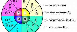
In electrical engineering, the need to switch electrical circuits often arises. Each electromechanical switching device has at least one pair of connecting contacts. Contrary to expectations, it is often possible to observe that the contacts heat up. The reason for this is the contact resistance of the contacts, which cannot be completely eliminated.
The contact spot is formed as a result of any contact of conductors. At the point of connection of the wires, a resistance always arises that exceeds the resistivity of the conductor materials. There are several reasons for this phenomenon, which will be discussed in this article. First, let’s find out what is meant by the term contact resistance.
Introduction
An electrical contact is one of the basic elements of any electrical circuit. Due to the increasing complexity of technical systems, the number and variety of types and forms of contacts, their modes and operating conditions are growing. The role of contacts becomes more responsible both in technical and technical-economic terms. All this requires a more intensive and in-depth study of physical processes in various modes and operating conditions of contacts, methods of engineering calculation and design, correct regulation of operating modes and conditions, development and research of new contact materials and new structural forms of contacts.
This article outlines the basic principles of operation, physical processes and phenomena occurring in electrical connectors, and identifies the basic concepts and their physical meaning. Factors that determine the reliability, durability and storage conditions of electrical connectors are given. Ways to increase reliability and durability are determined, and operating rules are outlined.
Our advantages
RosTechNadzor License No. 5742
The licensed organization ProfEnergia Engineering Center LLC guarantees the accuracy, objectivity and reliability of the results.
Verified instruments and equipment (SP No. 0889514)
Proven instruments and equipment (SP No. 0889514): Our campaign uses only high-quality instruments and equipment.
Free site visit and estimate
Free site visit and estimate: Our specialists will come to the site free of charge and calculate the cost.
25% more profitable than competitors
25% more profitable than competitors: We have fair prices. Individual discounts also apply.
Engineering Ph.D. in State
Candidates of Technical Sciences on staff: ProfEnergia has a very well-established team of qualified engineers with access to all types of work performed.
Bolted contact connections.
Contact connections made using bolts most often have defects due to the lack of washers at the junction of the copper core with a flat terminal made of copper or aluminum alloy, the absence of disc springs, direct connection of the aluminum tip to the copper terminals of equipment in rooms with an aggressive or humid environment , as a result of insufficient tightening of bolts, etc. Bolted contact connections of aluminum busbars for high currents (3000 A and above) are not stable enough in operation. If contact connections for currents up to 1500 A require tightening the bolts once every 1 - 2 years, then similar connections for currents of 3000 A and above require annual overhaul with the obligatory cleaning of the contact surfaces. The need for such an operation is due to the fact that in high-ampere busbars (busbars of power plants, etc.) made of aluminum, the process of formation of oxide films on the surface of contact joints occurs more intensively. The process of formation of oxide films on the surface of bolted contact joints is facilitated by different temperature coefficients of linear expansion of steel bolts and aluminum busbars. Therefore, when a short-circuit current passes through the busbar, when it operates with an alternating current load, deformation (compaction) of the contact surface of the aluminum bus occurs in it over a long distance as a result of vibration influences. In this case, the force tightening the two contact surfaces of the busbar weakens, the lubricant layer between them evaporates, etc. Due to the formation of oxide films, the contact area of the contacts, i.e. the number and size of contact pads (number of points) through which current passes decrease and, at the same time, the current density increases, which can reach thousands of amperes per square centimeter, as a result of which the heating of these points increases greatly. The temperature of the last point reaches the melting temperature of the contact material, and a drop of liquid metal forms between the contact surfaces. The temperature of the drop, rising, reaches a boil, the space around the contact connection is ionized, and there is a danger of a multiphase short circuit in the switchgear. Under the influence of magnetic forces, the arc can move along the switchgear busbars with all the ensuing consequences. Operating experience shows that, along with multi-ampere busbars, single-bolt contact connections also have insufficient reliability. The latter, in accordance with GOST 21242-75, are allowed for use at a rated current of up to 1,000 A, but are damaged already at currents of 400 - 630 A. Increasing the reliability of single-bolt contact connections requires taking a number of technical measures to stabilize their electrical resistance. The process of development of a defect in a bolted contact connection, as a rule, takes quite a long time and depends on a number of factors: load current, operating mode (stable load or variable), exposure to chemical reagents, wind loads, bolt tightening forces, contact pressure stabilization, etc. Transitional The resistance of a bolted contact connection depends on the duration of the current load. The contact resistance of contact connections gradually increases up to a certain point, after which a sharp deterioration of the contact surface of the contact connection occurs with intense heat generation, indicating an emergency condition of the contact connection. Similar results were obtained by specialists from Inframetrix (USA) during thermal tests of bolted contact joints. The increase in heating temperature during testing was gradual throughout the year, and then there was a period of sharp increase in heat release.
Ground resistance tests
Ground resistance measurement
There are acceptance and operational tests.
The first ones, based on the PUE, are carried out after completion of the installation of protective grounding. Electrical installations that have been put into operation are subject to operational tests regulated by PTEEP. With this type of test, examinations are carried out throughout the entire period of operation of the protective device.
In accordance with the rules, the resistance of the grounding structure must be measured once every six years. If there is a suspicion of damage to the grounding device, such a test is carried out more often.
Transition resistance measurements are carried out at least once a year.
In addition to measuring resistance, also during testing, a thorough inspection of all visible parts of the grounding device must occur.
Once every 12 years, it is necessary to carry out a detailed inspection with partial opening of the soil in places where corrosion is most likely to occur. If the soil in a given area behaves aggressively, then the number of such inspections increases.
Also, once every six years, the condition of the fuses is checked.
If the inspection revealed more than 50% damage, such a protective structure must be replaced without fail.
How to measure contact resistance correctly
There are certain rules that describe the correct measurement of Rn for switching devices. These include circuit breakers, all kinds of disconnectors and buses.
There are several measurement methods:
- a method when the counting is carried out directly and directly;
- using a multimeter (you can also use an ammeter or voltmeter);
- a method for measuring the unstable static behavior of a junction resistance.
Note! The first point involves the use of instruments for direct calculation with an error of less than 10%. It is most often used to measure Rn of a contact connection.
The contacts are not cleaned before measurement. They are connected to the terminals of the devices. At the same time, moving devices and opening contacts is contraindicated.
Formula for unstable static joint venture
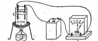
In the second method, the magnitude of the voltage drop is determined at a fixed current value at the junction that is being tested. The error of any device in a measuring system of this kind is no more than 3%. Initially, the resistance value is selected several times greater than expected. The calculation is performed using the formula: Rп = UPV2/IPA, where UPV2 is the figure shown by the PV2 voltmeter in V; IPA is the current measured by the ammeter PA in Am.
The static instability of the junction resistance is determined based on the root mean square change in Rn determined through repeated measurements. The error of such measurements is +/- 10%.
List of devices for measuring SP
How often to measure grounding PS
Grounding is a special connection of equipment to a grounding device (GD).
The memory is a device consisting of the following elements:
- grounding conductor (grounding circuit);
- grounding buses;
- grounding conductors.
A full inspection, including opening the soil and inspecting the condition of the grounding conductors and the conductors connecting them, is carried out once every 12 years. Unscheduled inspections are carried out after major repairs related to grounding elements. The period for checking and measuring the PS memory is assigned based on the recommendations of the organization that performed the previous check.
For your information. It is recommended to take measurements during the months of greatest freezing or drying of the soil.
The value of Rп, which lies within the regulated standards, ensures stable operation of switching devices. This, in turn, contributes to the uninterrupted and safe operation of the equipment.
Contact surface
The contact surface, like any solid body, always has roughness and waviness. An approximately geometric model of the contact surface can be considered as a certain wavy surface on which spherical protrusions are located. The height of the protrusions relative to the base of the waves is not the same. The statistical distribution of the heights of these protrusions is close to normal.
The presence of roughness and waviness leads to the fact that the two surfaces always contact only in separate “spots”.
The surface, which is a collection of points through which pressure is transmitted, is called the effective mechanical contact surface, and if it is a pure metal, that is, its surface is free of non-conducting films, then such a surface will also be an effective electrical contact surface.
The effective contact surface is a function of contact pressure.
Under the action of pressing force, the two surfaces are brought closer together due to the deformation of the contacting protrusions, and more and more individual protrusions come into contact. The approach of the contacting surfaces occurs until the sum of the reactions of the elastically deformed protrusions is equal to the pressing force N, that is, when:
where nk is the number of contacting protrusions; Ni is the reaction of the protrusion deformed by the amount Δi.
The size of the effective contact surface is equal to:
where r is the average radius of the protrusions, the value of which is determined by the cleanliness of the contact surfaces.
The relationship between the effective contact surface and contact pressure can be represented as:
for the case of contact along a line (for example, contact between the generatrix of a cylinder and a plane).
for the case of contact along a plane, where E is Young’s modulus; hm—maximum height of protrusions; no is the total number of protrusions on the “apparent” contact surface.
At contact pressures of the order of 0.015-1.0 kgf, which usually occur in practice in detachable contacts, the effective contact surface is negligible compared to the apparent contact surface. Usually it ranges from fractions to units of percent.
Metal connection and checking the presence of a grounding circuit
Starting the article, it is appropriate to answer the question: “What is metal bonding?” Metal bond is a quantity that characterizes the contact connection of a grounded object with a grounding device. During operation of an electrical installation, due to corrosion, short circuit or mechanical damage, breaks in the grounding circuit occur, which leads to the appearance of a dangerous potential difference, which in turn can lead to injury and damage to electrical equipment. If you touch an ungrounded electrical panel door, electrical equipment enclosure, or luminaire housing during maintenance, there is a risk of electric shock. Many sensitive electrical appliances, in principle, cannot operate without good grounding.
To avoid the above cases, it is necessary to measure metal bonds with the assistance of an electrical laboratory. The metal communication protocol based on the inspection results includes a report on the integrity of the conductors, the resistance value of the tested section of the circuit and the voltage value on the grounded equipment. The resistance of the test section is an indicator of the quality of the connection. The rules for the design of electrical installations of the Electrical Electrical Installations include permissible resistance values.
For measurements, a device from the electrical laboratory is used, which supplies current to the section being tested and shows the resistance of the circuit section. The resulting value, as a rule, should not exceed 0.05 Ohm. Metal communication testing is carried out both as part of acceptance tests and as part of preventive tests carried out every 2-3 years. The frequency of tests is determined by the operating organization based on the recommendations of GOST R 50571.16-2007, PTEEP, POTRRM and the state of the electrical installation. Metal bond testing can be carried out without disconnecting the voltage. The measurement of metal bond resistance must be entrusted only to certified laboratories, since without a Rostechnadzor certificate the protocol has no legal force for regulatory authorities. OJSC Energetik LTD offers metal communication measurements at prices significantly lower than market prices, due to the large volume of work carried out in Moscow and the Moscow region.
All materials are protected by the Russian Federation copyright law and the Civil Code of the Russian Federation. Full copying is prohibited without permission from the resource administration. Partial copying is permitted with a direct link to the source. Author of the article: team of engineers from OJSC Energetik LTD
Features of wear of contacts opened under current
The normal operating mode of the bulk of electrical connectors involves their opening and connection in a de-energized state. The exception is breakaway connectors and some other structures.
Sometimes it becomes necessary to open live electrical connectors. This is extremely undesirable, since this mode of operation sharply reduces the service life of the electrical connectors.
When the contacts are opened under current, there is a sharp increase in the transition resistance and voltage drop across them, which leads in accordance with the equation
to an increase in the temperature of the contacted protrusions, up to the melting temperature of the contact material. At the first moment of opening the contacts, a bridge is formed between them from the molten metal of the contact coating and the metal of the contacts themselves, which, with further divergence of the contacts, will thin out not in the middle, but closer to the positive electrode, where it will finally break. This phenomenon is similar to electrolysis. This process causes metal to transfer from one contact to another. This phenomenon is called bridging erosion of contacts.
When voltages and currents in the open circuit are less than certain values for specific contact materials (for example, for silver UI
As a result of erosion, the microgeometry of the contact surfaces changes, which leads to increased mechanical wear of the contact surfaces, since electrical erosion prevents the transition of the contact wear process from the running-in phase to the normal wear phase.
In the case when the voltage and current in the circuit being broken are greater than certain values (for example, for silver U > 12 V, I > 0.4 A), an electric arc occurs between the contacts when they open. The arc causes increased erosion of the contacts, both due to its thermal effect and due to the bombardment of the cathode by gas ions that are formed at the moment the arc burns. The mode of operation of electrical connectors with the formation of an electric arc between the contacts at the moment they open is extremely undesirable and must be excluded when operating electrical connectors. Even short-term operation of connectors in the electric arc formation mode practically reduces the resource of normal operation of the electrical connector to zero.
Mechanisms
For given physical and mechanical properties of a material, the parameters that determine the magnitude of the electrical contact resistance (ECR) and its change at the interface primarily relate to the surface structure and the applied load (contact mechanics). Metal contact surfaces typically have an outer layer of oxide material and adsorbed water molecules, resulting in capacitor-type junctions on low-contact protrusions and resistive-type junctions on high-contact protrusions, where sufficient pressure is applied to force the protrusions into the oxide layer, forming metal-to-metal contact patches. metal. If the contact patch is small enough, with dimensions comparable to or smaller than the electron mean free path, the resistance at the patch can be described by , whereby electron transfer can be described by ballistic conductivity. As a rule, over time, the contact patches expand and the contact resistance at the interface, especially on weakly contacting surfaces, decreases as a result of current welding and dielectric breakdown. This process is also known as drag creep. Mechanistic assessment of ECR phenomena must take into account the interplay of surface chemistry, contact mechanics, and charge transfer mechanisms.
Factors that cause
Contact resistance connects individual sections of the circuit to each other. At the junction, a mutual contact of current conduction is formed. Through this section, current from one branch can enter another. If you simply put the wires on top of each other, there will be no reliable connection. This is due primarily to the fact that the surface, no matter how smooth it may seem, consists of irregularities. With multiple magnification, this can be seen even on perfectly ground and polished materials.
Important! In practice, it will become clear that the area of real contact is much smaller than the visual one. Another factor in the occurrence of junction resistance is the film resulting from the oxidation of the conductor metal
Such films prevent the current from moving and tighten its direction at the points of contact. It is impossible to get rid of this completely, since its value is always greater than the resistivity of the conductor metal
Another factor in the occurrence of junction resistance is the film resulting from the oxidation of the conductor metal. Such films prevent the current from moving and tighten its direction at the points of contact. It is impossible to completely get rid of this, since its value is always greater than the resistivity of the conductor metal.
Touch spots and uneven contacts under a microscope
What is the frequency of measurements?
Before measuring the grounding resistance in one way or another, it is important to take into account the requirements of the PUE regarding the frequency of these tests. According to the main provisions of this document, they can be carried out in the following forms:
- routine examinations;
- extraordinary inspections;
- launch tests.
The frequency of each of these types of inspections is determined by the goals that they set for themselves. The frequency of inspections of the insulation resistance of station equipment is usually consistent with the inspection of the circuit breaker itself. Let's look at their different types in more detail.
Scheduled checks
The timing of planned activities is stipulated by instruction RD-34.22.121-87, as well as the requirements of the PUE. From these documents you can find out what is the frequency of visual inspection of visible parts of grounding devices, which according to them is organized at least once every six months. In addition, from the same standards it follows that at least once every 12 years, inspections of the structure must be carried out with the opening of the soil around it. Measurement of the resistance of grounding loops according to the same documents should be carried out at least once every 6 years.
Persons authorized to do so by the relevant authorities are responsible for conducting such inspections. The owner of a private house must fill out an application for them in advance with subsequent payment. Upon completion of the tests, he is obliged to provide the local energy service with a protocol for measuring the contact resistance between the elements of the closed circuit.
Extraordinary
Extraordinary measurements of circuit parameters should be carried out in the following emergency situations:
- After making changes to the design that are not provided for by the design, but affect the resistance to current flow (measurement of grounding in a private house should be carried out when moving it to another place).
- After emergency destruction and subsequent restoration of the ZK.
- Upon completion of the repair work.
The frequency of their holding is not regulated for obvious reasons.
Starting or introductory
Start-up or introductory grounding checks and resistance measurements are organized immediately after the installation of the protective circuit is completed (that is, on the eve of its delivery to the local energy service representative). To do this, you will need to invite a specialist from an electrical laboratory or other organization licensed to conduct such tests.
Based on the results of the inspection, an acceptance certificate is issued, which is the basis for the subsequent commissioning of the device and confirmation that all supply lines in private houses are grounded.
Test conditions
When organizing grounding testing activities, it is important to pay attention to the conditions in which they are supposed to be carried out. They must be taken into account at the test preparation stage, and upon completion they must be entered in a special journal. According to the requirements of current regulations (PUE, in particular), for this it is advisable to choose the summer season with sunny, dry weather, which allows you to obtain results that are closest to reality
This is explained by the fact that at such a time the soil is maintained in a fairly dry condition, corresponding to the actual operating conditions of the protective structure
According to the requirements of current regulations (PUE, in particular), for this it is advisable to choose the summer season with sunny, dry weather, which allows you to obtain results that are closest to reality. This is explained by the fact that at such a time the soil is maintained in a fairly dry condition, corresponding to the actual operating conditions of the protective structure.
When carrying out control measurements of permissible resistances in damp autumn weather, for example, the results obtained will be significantly distorted. This is explained by the fact that soil saturated with moisture significantly increases the conductivity of the soil. In order to avoid all these difficulties and get a value close to the real value, the easiest way is to use the services of professionals. To do this, you must contact a special electrical laboratory that has a license to carry out the relevant work.
Upon arrival at the site, specialists will identify all factors and organize testing of protective equipment in accordance with the requirements of current regulations. Upon completion of the entire test cycle, they will also draw up a grounding resistance measurement protocol, a sample of which is presented below.
Protocol for testing grounding resistance
The influence of the built-in current transformer (CT) on the measurement of Rac of tank circuit breakers
When the measuring current is supplied through the pole of the tank switch, a transient process occurs in the secondary winding of the CT, which manifests itself in the induction of a voltage pulse into the primary circuit, which gradually decreases to zero. This changing voltage is summed up by the voltage drop across Rac, created by the measuring current, and is perceived by the microohmmeter as an additional (introduced from the secondary winding of the CT) resistance connected in series with Rac. and changing over time. The decay time of the transient process of the drop in the introduced resistance depends on many factors and can vary from 1.0 to 60 s. The transient process in a circuit containing a CT occurs not only when the current is turned on, but also when it is turned off.
Standards for each type
In order to understand what regulatory and operational indicators should be for each type:
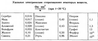
Does the resistivity of a conductor depend on temperature? How does resistance depend on temperature?
- For electrical installations. Ground resistance measurements should be carried out in close proximity to the substation. Depending on the load, this figure can be 60, 30 or 15 Ohms. It is also worth considering natural grounding electrodes - for them these values should be 8, 4 or 2 Ohms, respectively. All three quantities depend on the network voltage. 60 and 8 Ohms are allowed for a single-phase network of 200 volts. 30 and 4 Ohms - for three-phase with a voltage of 380 volts. The minimum values (15 and 2 Ohms) are for 660 volts. During operation, the resistance of the ground loop should also not fall below the values described in the paragraph above.
- For a distribution point or substation. For installations with voltages above 100 kilovolts (100 thousand volts), the grounding conductivity during the commissioning of the network and during its operation also remains unchanged and is 0.5 Ohm. In this case, the mandatory requirements for testing are a solid grounding type and connected to a neutral circuit. There are also standards for less powerful installations, in which the voltage lies between 3 and 35 kilovolts. In this case, you need to divide 250 by the calculated ground fault current - the resulting value will be the required resistance in Ohms. The indicator, according to PTEEP, should not exceed 10 Ohms in any case.
- For overhead power lines. It is calculated depending on the conductivity of the soil on which the power line supports stand:
- for soil with a resistivity of less than 100 Ohms per meter - 10 Ohms;
- with a resistivity of 100...500 Ohms per meter - 15 Ohms;
- with a resistivity of 500...1000 Ohms per meter - 20 Ohms;
- with a resistivity of 1000...5000 Ohms per meter - 30 Ohms.
For power lines with a current voltage of less than 1000 volts - up to 30 Ohms (for supports with lightning protection). Otherwise, the resistance should be 60, 30 or 15 ohms for networks with voltages up to 660, 380 or 220 volts, respectively.
What is contact resistance
Transition resistance is the resistance that occurs in places on a conductor where current passes from one wire to another or from a conductor to an electrical device. This happens in cases where there is a poor connection or contact of the wires.
Wire contact options
Based on the laws of physics, in such places, when a load current passes, a certain heat is released. Its value is equal to the square of the passing current divided by the resistance of the contact point. Such places can reach quite high temperatures and, if they come into contact with materials that are susceptible to burning or melting, can cause a fire and unstable operation of the equipment.
Note! It is these contacts that are the main cause of fire situations, explosions and short circuits. The danger also arises due to the fact that such contacts are difficult to detect, and the mechanisms for protecting networks and devices, even if they are modern, cannot always prevent an emergency.
Contact surface
What does resistance depend on?
Total resistance
The following reasons influence the value of PS:
- current density at the point of contact closure;
- the force with which the joint surfaces are compressed;
- material from which the contacts are made;
- level of oxidation of metal surfaces.
Important! Any contact connection Rк is the sum of a pair of resistances: R (the metal from which the contact is made) and Rп (transition) – Rп = R + Rк.
PS contact
Factors influencing the value of contact resistance
Resistivity
Before talking about factors, you need to know what contacts are. They differ in the type of contact surface:
- point – connection occurs at a point;
- linear - touching along a line;
- planar – contact along a plane.
Examples of point connections - “sphere - sphere”; “top of a cone – plane”, “sphere – plane”, etc. Linear contacts include: “torus – plane”, “cylinder – plane”, “cylinder – cylinder”, etc.
The contact area of contacts can be calculated using the formula:
Spr = F/σ,
Where:
- F – contact compression force;
- σ is the temporary resistance of the contact material to compression.
There are different connection methods:
- mechanical (twisting, bolt clamps, crimping);
- welding;
- soldering.
The magnitude of the transition resistance is determined by the formula:
Rп = knx/(0.102*Fk)n,
Where:
- knx – coefficient determined by the material, contact shape, surface condition;
- Fk is the force with which the contacts are compressed;
- n – exponent showing the number of points of contact.
Exponent for different types of contacts:
- for point – n = 0.5;
- for linear – n = 0.5-0.7;
- for planar (surface) – n = 0.7-1.
There are standards for contact resistance adopted according to GOST 24606.3-82.
Factors influencing Rп
Attention! Oxidation of metal surfaces at joints can be combated by wiping the contacts with alcohol-containing solutions. It is permissible to lubricate bolted joints with grease, this will help reduce the access of oxygen and slow down the oxidation process
Regular drawing of contacts and twists, inadmissibility of copper and aluminum connections, polishing of contactor jaws - all these are measures to combat transient resistance.
For your information. Poor pressing of the contacting surfaces causes not only an increase in resistance, but also an increase in the degree of heating of the conductors.
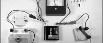
Measurement technique
GOST 21534-76 oil. methods for determining the content of chloride salts (with changes n 1, 2, 3, as amended)
There are regulations for measuring Rp for switching devices: circuit breakers, disconnectors, busbars and connecting busbars and other equipment.
The measurement methods are as follows:
- direct counting method;
- voltmeter-ammeter method;
- measurement of static instability Rп.
In the first testing method, instruments are used that allow direct reading, taking into account the error (±10%). With this method, the resistance of the contact connection is measured.
Important! The tested surfaces of the contact part are not cleaned or treated before measurement. The contact part is articulated (closed) and connected to the terminals of the devices. Opening contacts and moving test leads are not allowed.
Opening contacts and moving test leads are not allowed.
Using the voltmeter-ammeter method, the magnitude of the voltage drop (at a set current value) across the junction being tested is determined.
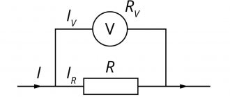
Measuring setup diagram
All measurement errors of devices included in the circuit must be within ±3%. The value of R1 is selected two orders of magnitude greater than the expected measured resistance.
Calculation of measurement results is performed according to the formula:
Rп = UPV2/IPA,
Where:
- UPV2 – result obtained on voltmeter PV2, V;
- IPA – current measured by ammeter PA, A.
Static instability Rп is determined by finding the value of the standard deviation Rп from the results of numerous measurements.
Attention! Transition resistance is measured using one of the methods discussed above. The contact part is opened and closed again before each test, removing the electrical load. The required result is obtained using the formulas in Fig.
below
The required result is obtained using the formulas in Fig. below.
Formulas for calculating the result using the static instability method
The error of the results obtained with this method lies within ±10% (with a probability of 0.95).
List of instruments used for measurements
Measurements of Rp transitions are also carried out with an MMR-610 micrometer. As a result of the work, the DC resistance of machine contacts and other connections is tested. Two types of measurements are carried out:
- unidirectional current;
- bidirectional current.
In the first case, the value of active resistance R is not displayed, but this method speeds up the measurement process where there are no internal stresses and electrostatic forces. In the second case, the device eliminates errors (errors) arising from the presence of such forces and stresses in the structure being tested.
Microohmmeter MMR – 610
The data obtained as a result of measurements (checks) is recorded in the protocol, in accordance with PUE-7, clause 1.8.5. The protocol is stored together with equipment passports.
Sample inspection report
Subscribe to RSS!
Subscribe to RSS and receive blog updates!
Receive updates by email:
- Transistor switch with current limitation June 3, 2020
- Charger for screwdriver batteries based on XL4015 April 5, 2020
- Car charger with current stabilization for L200 March 19, 2020
- Six-digit indicator on TM1637 March 13, 2020
- Adjustable current stabilizer on L200 March 11, 2020
- Charger for car batteries - 237
- Current stabilizer on LM317 - 173
- Voltage stabilizer on KR142EN12A - 124,884 views
- Reversing electric motors - 101
- Charger for screwdriver batteries - 98,420 views
- Sitemap - 96
- Charger for screwdriver - 88
- Homemade welding machine - 87
- Transistor circuit KT827 - 82
- Adjustable current stabilizer - 81
- DC-DC (4)
- Automatic pumping of water from a drainage well (5)
- Automatic (34)
- Car (3)
- Antennas (2)
- Assembler for PIC16 (3)
- Power supplies (30)
- Well drilling (6)
- Life (11)
- Generators (1)
- Signal generators (8)
- Sensors (4)
- Engines (7)
- For the garden (11)
- Chargers (17)
- Radio protection (8)
- Winter water supply for a bath (2)
- Measurements (34)
- Switching power supplies (2)
- Indicators (6)
- Indication (10)
- As my grandfather used to say... (1)
- Switches (6)
- Logic circuits (1)
- Feedback (1)
- Lighting (3)
- Programming for Beginners (16)
- Programs (1)
- Works by visitors (7)
- Radio transmitters (2)
- Radio stations (1)
- Regulators (5)
- Repair (1)
- Homemade products (12)
- Homemade mobile sawmill (3)
- Homemade water supply (7)
- Self-calculations (37)
- Welding (1)
- Alarms (5)
- Directory (13)
- Stabilizers (16)
- Construction (2)
- Timers (4)
- Thermometers, thermostats (27)
- Technologies (21)
- ULF (2)
- Signal conditioners (1)
- Electricity (4)
- This will come in handy (12)
Transition resistance - contact
Transitional contact resistance is the resistance of an electrical contact, consisting of the resistance arising from the narrowing of the cross-section of the material in its elementary tubercles through which current passes, and the resistance of poorly conductive oxide, oil, sulfide, gas films and dust.
| Time schedule for testing installation connections for reliability. |
The contact resistance is measured with a milliohmmeter using the voltmeter and ammeter method.
| Dependence of transition resistance on contact pressure. |
The transition resistance of contacts is caused not only by the phenomenon of contraction of current lines. The contacting surfaces are covered with adsorbed molecules of the gas in which the contacts were located before they were closed.
The contact resistance can increase tens and hundreds of times due to oxidation of the contact surfaces. In particular, such a deviation is often caused by heating the contacts above 70 - 75 C.
Contact contact resistance may increase due to contact corrosion and other phenomena. In addition, with a small pressure, sensitivity to vibration increases, which leads to a change in resistance and an increase in intrinsic noise (Contacts. Vibrations can be caused by mechanical influences and current fluctuations in the coil, as well as leakage fluxes from neighboring relays.
The transition resistance of the contact decreases with increasing current in such a way that the transition voltage drop in the contact remains constant. For natural graphite brushes it is 0 7 - 1 2 V per brush, and for electrographite brushes it is 0 8 - 1 7 V. Consequently, when the brush is loaded with a current equal to, for example, 50 s, energy equal to 40 - 80 watts will be released in a thin layer between the brush and the ring or collector, turning into heat. When points directly touching each other break, either an electric arc occurs and is held for a short time, or a very short-term electric spark jumps. This occurs when the capacitance parallel to the brush contact, including the capacitance of the excitation cables and the capacitance of the windings of the compensator rotor or armature pathogen is of sufficient size. At low currents, these arcs or sparks can be microscopically small and therefore invisible to the eye. Larger currents are accompanied by more noticeable arcs or sparks, especially when observed in the dark.
| Scheme for measuring the minimum contact pressure of the MKP-110 switch. |
The contact resistance is measured with a microohmmeter when the switch is on.
| Scheme for measuring the minimum contact pressure of the MKP-110 switch. |
The contact resistance is measured with a micrometer when the switch is on.
The transition resistance of the contacts (Kkot) on average can be taken equal to 0 05 - 0 1 ohm.
The transition resistance of contacts immersed in oil or simply lubricated with oil is almost always less than for dry contacts, since the oil helps clean the surfaces of contamination, and after the destruction of the oxide film due to friction during switching, it prevents re-oxidation. Copper and brass contacts in transformer oil hardly oxidize. The resistance of steel contacts during this time increased by more than 40 times, while the final resistance values of copper and brass contacts, both bare and tinned and nickel-plated, are almost equal to the initial ones.
The contact resistance in microohms is determined by the formula (2 - 8), and in the vast majority of cases, the contacts of switching devices should be considered point contacts, assuming / n0 5, which gives a certain margin of reliability.
Difficulty in measuring resistance in various connections
In the power electrical circuit of the pole of a high-voltage circuit breaker, in addition to the transition resistance of the contacts, there is also the resistance of various connections. Most often, devices are equipped only with a measuring cable with an alligator clip, and if it is incorrectly connected to the contacts between the hardware clip and the input pin, the transition resistance may be overestimated, the device will show a value higher than the rated value, and completely unnecessary repairs of the switch contacts will be performed .
If you remove potential signals not from hardware terminals, but from pins, then only the transition resistance of the switch contacts will be included in the measured section of the circuit. But it is often not possible to attach the “crocodiles” directly to the studs due to lack of access to them, so the device must be equipped with special remote potential contacts.